Transcription
EECS 142Lecture 15: Introduction to MixersProf. Ali M. NiknejadUniversity of California, BerkeleyCopyrightA. M. Niknejadc2005 by Ali M. NiknejadUniversity of California, BerkeleyEECS 142 Lecture 15 p. 1/22– p.
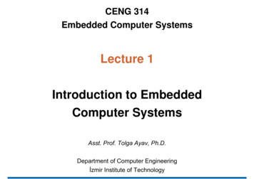
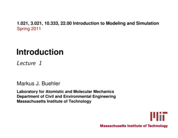
MixersRFIFRFLOIFLOAn ideal mixer is usually drawn with a multiplier symbolA real mixer cannot be driven by arbitrary inputs.Instead one port, the “LO” port, is driven by an localoscillator with a fixed amplitude sinusoid.In a down-conversion mixer, the other input port isdriven by the “RF” signal, and the output is at a lower IFintermediate frequencyIn an up-coversion mixer, the other input is the IF signaland the output is the RF signalA. M. NiknejadUniversity of California, BerkeleyEECS 142 Lecture 15 p. 2/22– p.
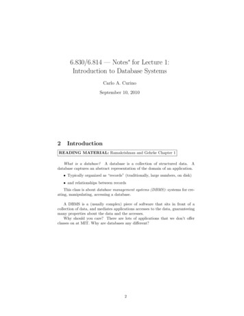
Frequency Translationdown-conversionIFIFRFLOAs shown above, an ideal mixer translates themodulation around one carrier to another. In a receiver,this is usually from a higher RF frequency to a lower IFfrequency. In a transmitter, it’s the inverse.We know that an LTI circuit cannot perform frequencytranslation. Mixers can be realized with eithertime-varying circuits or non-linear circuitsA. M. NiknejadUniversity of California, BerkeleyEECS 142 Lecture 15 p. 3/22– p.
Ideal MultiplierSuppose that the input of the mixer is the RF and LOsignalvRF A(t) cos (ω0 t φ(t))vLO ALO cos (ωL0 t)Recall the trigonometric identitycos(A B) cos A cos B sin A sin BApplying the identity, we havevout vRF vLOA(t)AL O {cos φ (cos(ωLO ω0 )t cos(ωLO ω0 )t)2 sin φ (sin(ωLO ω0 )t sin(ωLO ω0 )t)}A. M. NiknejadUniversity of California, BerkeleyEECS 142 Lecture 15 p. 4/22– p.
Ideal Multiplier (cont)Grouping terms we havevoutA(t)AL O{cos ((ωLO ω0 )t φ(t)) 2cos ((ωLO ω0 )t φ(t))}We see that the modulation is indeed translated to twonew frequencies, LO RF and LO RF . We usuallyselect either the upper or lower “sideband” by filteringthe output of the mixerhigh-pass or low-passRFIFLOA. M. NiknejadUniversity of California, BerkeleyEECS 142 Lecture 15 p. 5/22– p.
Mixer FilterLO-RFRFLOLO RFNote that the LO can be below the RF (lower sideinjection) or above the RF (high side injection)Also note that for a given LO, energy at LO IF isconverted to the same IF frequency. This is a potentialproblem!A. M. NiknejadUniversity of California, BerkeleyEECS 142 Lecture 15 p. 6/22– p.
Upper/Lower Injection and ImageExample: Downconversion MixerRF 1GHz 1000MHzIF 100MHzLet’s say we choose a low-side injection:LO 900MHzThat means that any signals or noise at 800MHz willalso be downconverted to the same IFA. M. NiknejadUniversity of California, BerkeleyEECS 142 Lecture 15 p. 7/22– p.
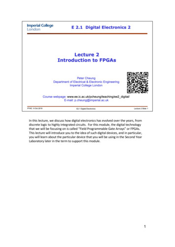
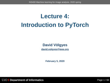
Receiver ApplicationIFRF IMAGELNALOThe image frequency is the second frequency that alsodown-converts to the same IF. This is undesirablebecuase the noise and interferance at the imagefrequency can potentially overwhelm the receiver.One solution is to filter the image band. This places arestriction on the selection of the IF frequency due tothe required filter QA. M. NiknejadUniversity of California, BerkeleyEECS 142 Lecture 15 p. 8/22– p.
Image RejectionIMAGE REJECTIFRF IMAGELNALOSuppose that RF 1000MHz, and IF 1MHz. Thenthe required filter bandwidth is much smaller than 2MHzto knock down the image.In general, the filter Q is given byRFω0 Q BWBWA. M. NiknejadUniversity of California, BerkeleyEECS 142 Lecture 15 p. 9/22– p.
Image Reject FilterIn our example, RF 1000MHz, and IF 1MHz. TheImagine is on 2IF 2MHz away.Let’s design a filter with f0 1000MHz andf1 1001MHz.A fifth-order Chebyshev filter with 0.2 dB ripple is downabout 80 dB at the IF frequency.But the Q for such a filter is103 MHzQ 1031MHzSuch a filter requires components with Q 103 !A. M. NiknejadUniversity of California, BerkeleyEECS 142 Lecture 15 p. 10/22–p
RF FilteringIF 1IF 2LNALO 1LO 2The fact that the required filter Q is so high is related tothe problem of filtering interferers. The very reason wechoose the superheterodyne architecture is to simplifythe filtering problem. It’s much easier to filter a fixed IFthan filter a variable RF.The image filtering problem can be relaxed by usingmulti-IF stages. Instead of moving to such a low IFwhere the image filtering is difficult (or expensive andbulky), we down-convert twice, using successively lowerIF frequencies.A. M. NiknejadUniversity of California, BerkeleyEECS 142 Lecture 15 p. 11/22–p
Direct Conversion ReceiverRFIF DCk ageaLO leLNALO RFA mixer will frequency translate two frequencies,LO IFWhy not simply down-convert directly to DC? Anotherwords, why not pick a zero IF?This is the basis of the direct conversion architecture.There are some potential problems.A. M. NiknejadUniversity of California, BerkeleyEECS 142 Lecture 15 p. 12/22–p
Direction ConversionFirst, note that we must down-convert the desired signaland all the interfering signals. In other words, the LNAand mixer must be extremely linear.Since IF is at DC, all even order distortion now plaguesthe system, because the distortion at DC can easilyswamp the desired signal.Furthermore, CMOS circuits produce a lot of flickernoise. Before we ignored this source of noise becuaseit occurs at low frequency. Now it also competes withour signal.Another issue is with LO leakage. If any of the LO leaksinto the RF path, then it will self-mix and produce a DCoffset. The DC offset can rail the IF amplifier stages.A. M. NiknejadUniversity of California, BerkeleyEECS 142 Lecture 15 p. 13/22–p
Direct Conversion (cont)Example: If the IF amplifier has 80 dB of gain, and themixer has 10 dB of gain, estimate the allowed LOleakage. Assume the ADC uses a 1V reference.To rail the output, we require a DC offset less than10 4 V. If the LO power is 0 dBm (316mV), we require aninput leakage voltage 10 5 V, or an isolation betterthan 90 dB!A. M. NiknejadUniversity of California, BerkeleyEECS 142 Lecture 15 p. 14/22–p
Phase of LOIn a direction conversion system, the LO frequency isequal to the RF frequency.Consider an input voltage v(t) A(t) cos(ω0 t). Since theLO is generated “locally”, it’s phase is random relativeto the RF input:vLO ALO cos(ω0 t φ0 )If we are so unlucky that φ0 90 , then the output of themixer will be zeroZA(t)ALO sin(ω0 t) cos(ω0 t)dtT A(t)ALOZsin(ω0 t) cos(ω0 t)dt 0TA. M. NiknejadUniversity of California, BerkeleyEECS 142 Lecture 15 p. 15/22–p
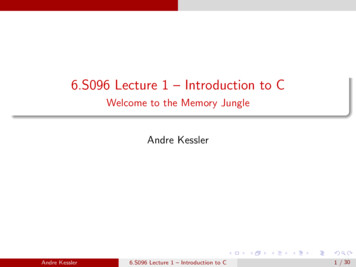
IQ-Mixercos(ωLO t)IRFQsin(ωLO t)To avoid this situation, we can phase lock the LO to theRF by transmitting a pilot tone. Alternatively, we canuse two mixersAs we shall see, there are other benefits to such amixer.A. M. NiknejadUniversity of California, BerkeleyEECS 142 Lecture 15 p. 16/22–p
AM ModulationWe can see that an upconversion mixer is a naturalamplitude modulatorIf the input to the mixer is a baseband signal A(t), thenthe output is an AM carriervo (t) A(t) cos(ωLO t)How do we modulate the phase? A PLL is one way todo it. The IQ mixer is another way.Let’s expand a sinusoid that has AM and PMvo (t) A(t) cos(ω0 t φ(t)) A(t) cos ω0 t cos φ(t) A(t) sin ω0 t sin φ(t) I(t) cos ω0 t Q(t) sin ω0 tA. M. NiknejadUniversity of California, BerkeleyEECS 142 Lecture 15 p. 17/22–p
I-Q PlaneQφI(t) A(t) cos φ(t)IQ(t) A(t) sin φ(t)We can draw a trajectory of points on the I -Q plane torepresent different modulation schemes.The amplitude modulation is given byI 2 (t) Q2 (t) A2 (t)(cos2 φ(t) sin2 φ(t)) A2 (t)A. M. NiknejadUniversity of California, BerkeleyEECS 142 Lecture 15 p. 18/22–p
General ModulatorThe phase modulation is given bysin φ(t)Q(t) tan φ(t)I(t)cos φ(t)or 1φ(t) tanQ(t)I(t)The IQ modulator is a universal digital modulator. Wecan draw a set of points in the IQ plane that representsymbols to transmit. For instance, if we transmitI 0/A and Q 0, then we have a simple ASK system(amplitude shift keying).A. M. NiknejadUniversity of California, BerkeleyEECS 142 Lecture 15 p. 19/22–p
Digital Modulation: BPSK/QPSKQQ011010I00I11For instance, if we transmit I(t) 1, this representsone bit transmission per cycle. But since the I and Qare orthogonal signals, we can improve the efficiency oftransmission by also transmitting symbols on the Q axis.If we select four points on a circle to represent 2 bits ofinformation, then we have a constant envelopemodulation scheme.A. M. NiknejadUniversity of California, BerkeleyEECS 142 Lecture 15 p. 20/22–p
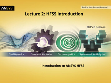
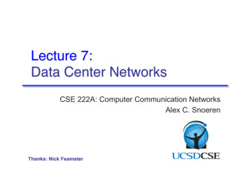
Modulation WaveformsThe data wave form(left) is modulatedonto a carrier (below).The first plot showsa simple on/off keying. The second plotshows binary phaseshift keying on onechannel . M. Niknejad23456-1University of California, BerkeleyEECS 142 Lecture 15 p. 21/22–p
More Bits Per CycleQQ010001011100000II111101110Eventually, the constellation points get very closetogether. Because of noise and distortion, the receivedspectrum will not lie exactly on the constellation points,but instead they will form a cluster around such points.If the clusters run into each other, errors will occur inthe transmission.We can increase the radius but that requires morepower.A. M. NiknejadUniversity of California, BerkeleyEECS 142 Lecture 15 p. 22/22–p
Image Reject Filter In our example, RF 1000MHz, and IF 1MHz.The Imagine is on 2IF 2MHz away. Let’s design a filter with f0 1000MHz and f1 1001MHz. A fifth-order Chebyshev filter with 0.2dB ripple is down about 80dB at the IF frequency. But the Q for such a filter is Q 103MHz 1MHz 103 Such a fil