Transcription
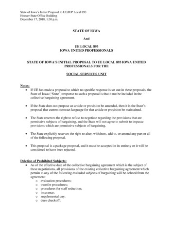
Iowa Department of TransportationOffice of DesignGeopak Project Manager21B-65Design ManualChapter 21Automation ToolsInstructionsOriginally Issued: 03-06-09Hyperlinked IndexStart Geopak and Project managerGeopak Project Manager SetupCreate New ProjectUser PreferencesFeature PreferencesCOGO preferencesCreate Project UserGeopak Road Project dialogGeopak Project Directory Structure (“projdbs” folder)The Working AlignmentRoad Tools - paletteStart Geopak and Project ManagerGeopak is activated through the MicroStation menu as shown below:Applications Bentley Civil Activate BENTLEY CIVILAfter Geopak is activated, the Project Manager dialog may be accessed through the Geopak RoadTools palette, or directly from the pull-down menu, as shown below. The Road Tools palette isshown below, right.Applications Road ROAD Tools or Applications Road Project ManagerPage 1 of 13
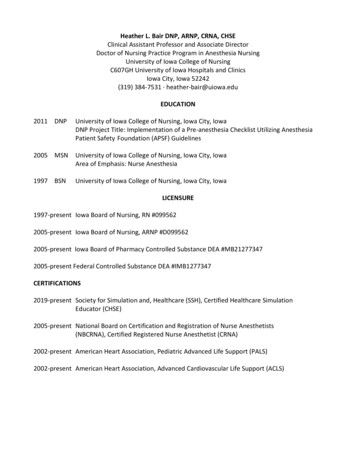
Chapter 21 Automation Tools InstructionsSection 21B-65 – Geopak Project ManagerGeopak Project Manager SetupThe Geopak Project Manager is used to organize information associated with each specific designproject. The following information is stored as part of a project: The values in the Geopak User Preferences dialog will reset to the values stored with theselected project. This eliminates the need to reset the Geopak User Preferences manuallyeach time you switch to a new project.Project Manager is also used to store Design file information associated with a project.Working Alignments will be discussed later.Coordinate Geometry information is associated with centerlines, existing profiles,proposed profiles, cross sections, etc. for each specific alignment within a given project.This information can also be stored in Project Manager.The name of the existing and proposed Digital Terrain Model, (DTM,) files can be storedwith Project Manager. DTM’s will be discussed elsewhere.There are 2 steps to creating a project in Geopak::1. Create the project2. Create users for the projectTo create a new projectAccess Project Manager as previously shown, and also shown below:Applications Road Project ManagerSelect the Current Working Directory, as shown below.Page 2 of 13
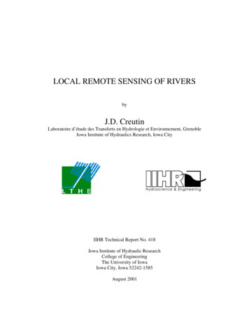
Chapter 21 Automation Tools InstructionsSection 21B-65 – Geopak Project ManagerTo access the Create New Project dialog, select Projects New from the Project Managerpull-down menu, shown below.In the Create New Project dialog, complete the following information:Project Name – The name of the new project being creating. In the example above, thefile “GEOPAK Training.prj” will be created in the directory that was specified in the ProjectManager dialog.Working Directory –Leave the Working Directory field blank - If this field is left blank, Geopak will usethe same directory as the location of the currently opened MicroStation design file toopen or save all Geopak related files. Use this option if all Geopak related files are tobe stored in the same directory as the MicroStation design files.Specify a Working Directory - If a multiple directory structure is being used for theproject, and the Geopak related files are to be stored in a different directory than theone that contains the MicroStation design file, the alternate directory can be specifiedby use of the Working Directory field.Job Number – This is the 1 to 3 digit alpha/numeric designation to be used by Geopak tocreate a Coordinate Geometry (COGO) database for the project. In the example above,using the three characters 123, a Coordinate Geometry database named job123.gpk willbe created in the directory that is specified as the Working Directory. The Select buttonis used to select a previously created GPK file for use by this project.Project Description – The Project Description is optional.Preferences – Select this button to access the User Preferences dialog shown below.Page 3 of 13
Chapter 21 Automation Tools InstructionsSection 21B-65 – Geopak Project ManagerUser PreferencesIt is easy to set or change the number of decimal places for output files, station formatting,coordinate format, English or Metric units, etc. These parameters are not only utilized by coordinategeometry, but also by many of the other Geopak functions.Once these preferences have been set, they are stored in a MicroStation resource file. Every timeGeopak is started, the settings of this dialog box are retained from the last design session. If you areworking on multiple projects with different units and different Working directories, The UserPreferences will need to be manually adjusted each time you open Geopak. Each option on theUser Preferences dialog is explained in the following sections:Unit System (Metric, English)Options are Metric and English. The Unit parameter affects every Geopak component.Coordinates (NE, XY)Sets either NE (Northing/Easting) or XY coordinate values in Coordinate Geometry andLabeling components.Direction (Bearing, Azimuth)Sets the direction format for such variables as line direction in Coordinate Geometry, Labelingand Components within the D&C Manager.Station (1 234, 12 34, 1234)Sets the format for station variables in Coordinate Geometry, Labeling, and components withinthe D&C Manager.Output AccuracyDistance (0 to 6 decimal places)Sets the number of decimal places for most non-station and non-angle variables in theGEOPAK Coordinate Geometry, Labeling, and components within the Design andComputation Manager. Variables affected by the Distance Decimal parameter includepoint coordinates, curve parameters such as length and radius, inverse distance,elevations, etc.Station (0 to 6 decimal places)Sets the number of decimal places for station variables in Coordinate Geometry, Labelingand components within the Design and Computation Manger.Page 4 of 13
Chapter 21 Automation Tools InstructionsSection 21B-65 – Geopak Project ManagerAngle Seconds (0 to 6 decimal places)Sets the number of decimal places for angle variables in Coordinate Geometry, Labelingand components within the Design and Computation Manger. Variables affected by theAngle Sec. Decimal parameter include curve delta and degree, bearings and inverseangles.Working DirectorySimply stated, the Working Directory is where Geopak will “look” for and store files. Theworking directory can be assigned in one of two ways:Leave the Working Directory field blank - If this field is left blank, Geopak will use the samedirectory as the location of the currently opened MicroStation design file to open or save allGeopak related files. Use this option if all Geopak related files are to be stored in the samedirectory as the MicroStation design files.Specify a Working Directory - If a multiple directory structure is being used for the project, andthe Geopak related files are to be stored in a different directory than the one that contains theMicroStation design file, the alternate directory can be specified by use of the WorkingDirectory field.The hour-glass “browse” button can be clicked to select the Working Directory .Feature PreferencesThe Feature Preferences option is used to assign the database that will be used for mappingsurvey data and visualizing COGO data. Selection of the Feature Preferences button activatesthe dialog shown below.Feature Database (SMD File text field)The symbology for the elements drawn from the survey data is determined by the featurecode of that element. These feature codes are stored in a database, the Survey ManagerDatabase (smd file) that can be assigned as desired.When the survey data is being mapped, as each element is created, the feature of thatelement is searched for in the .smd file. If a match is found, then the symbology for thatfeature is used. If a match is not found and there is a feature named “default” in the .smdfile, then the “default” feature symbology is used. If the feature is not found in the .smd fileand no “default” feature is defined in the .smd file, the current Microstation symboogy isused.The hour-glass “ Select SMD file” icon may be used to select the .smd file from a list. TheIowa DOT standard .smd file is located in the following SMDFiles\IAFEA07.smdPage 5 of 13
Chapter 21 Automation Tools InstructionsSection 21B-65 – Geopak Project ManagerEdit SMD (book icon)When the Apply Best Match Feature check-box ( ) is checked, the best match from thefeature survey preference database is utilized. This option allows placement of one featurein the database per item and locate derivatives, (variances), of that feature in the field.(Example: Assume that feature EP is for “Edge of Pavement”, but in the field there arethree different EP’s that need to be located. The different EP chains can be located asEP1, EP2, and EP3. During the mapping process, these features are matched to the Edgeof Pavement feature EP in the database. Therefore, multiple EP features do not have tobe defined in the database.)Plot Scale (text field)Denotes the scale utilized for drawing graphics. The sizing of the element to be placed inthe design file can be further controlled through the Survey Manager Database.Use Shared Cells (check-box)If checked ( ), the feature symbols will be placed as Shared CellsPoint Label Redraw (option field)Allows for two options: Position by SMD Settings, and Position Relative to SymbolOK (button) - Accepts the dialog settings and closes the Feature Preferences dialog.Cancel (button)Closes the Feature Preferences dialog without accepting any changes to the settings.COGO PreferencesThe COGO Preferences dialog is as shown below.The Job (GPK) Open Mode has three options: Create, No Create, QueryThree Directory fields: Job (GPK), COGO Input File, and COGO Output FileGeopak will automatically open the COGO database in the Working Directory. If none isfound, an Alert message, shown below, will appear and the software will respond in one ofthree ways, dependant on the setting in the Job (GPK) Open Mode field.Page 6 of 13
Chapter 21 Automation Tools InstructionsSection 21B-65 – Geopak Project ManagerCreateThe software will create a new database automatically if the Job Open Mode is set toCreate.No CreateThe software will not create a new database and the COGO dialog box will not beopened.QueryThe software will prompt the user whether to create a new COGO database as shownabove. We recommend leaving this option set to Query.Redefinition of elements (check-box)The Redefine function will allow overwriting of COGO elements. Checking this check-box( ) will force the Redefine functions on when COGO is activated. Note: Redefine can beturned on/off directly from the COGO dialog after COGO has been activated.Force Redefine off Upon COGO Activation (check-box)If the Redefine function left ON the last time COGO was exited, checking this check-box( ) will force the Redefine function to be OFF. It is recommended to check ( ) this option.Show this dialog at startup (Check-box)Checking ( ) this check-box will force the User Preferences to display at start-up.OK and Cancel buttons perform normally.After User Preferences have been selected, click the OK button, then select OK from the CreateNew Project dialog to create the project. A file, with the name supplied, will be created in thespecified directory. This file stores the name of the project, the job number and the optional projectdescription.After the project has been created, the name appears in the Project Manager dialog. Select theproject and click OK to open the project.Creating Project UsersA Project User must be selected to continue.Users New, as shown below.If none exist, one must be created by selectingPage 7 of 13
Chapter 21 Automation Tools InstructionsSection 21B-65 – Geopak Project ManagerGeopak allows multiple users to simultaneously access the Coordinate Geometry database (.gpk file).In order to keep track of COGO input and Output files, each person accessing the .gpk file isassigned a user name and operator code.Key in the Name, Full Name and OP Code (Operator Code initials) for the new user. TheDescription is optional.Select OK to create the new user.You will be prompted to define a password to protect the user name. Select Yes or No.The new user is created, and the name is added to the Project User dialog box as shown below.Select a user name, and pick OK to open the Geopak Road Project dialog, shown below.Page 8 of 13
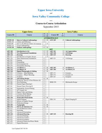
Chapter 21 Automation Tools InstructionsSection 21B-65 – Geopak Project ManagerGeopak Road Project dialogEach item on the Road Project dialog represents a specific Geopak function. Many of the topicswill be explained in separate instruction files.FileThe File menu has two options: Close and Exit.RememberThe toggle options on the Remember menu include Project and User, (or none), and instructsGeopak to automatically open to either the last Project or the last User, when the ProjectManager is opened. Experimentation will provide you with the best option for your personalsituation.OptionsThe Options menu provides one toggle option – the Auto Sink function, on or off. With AutoSink turned on, selecting any of the Road Project dialog options will automatically sink theRoad Project dialog behind the MicroStation window. After the selected dialog box function isclosed, the Road Project dialog will automatically “pop” back to the top. Experimentation willprovide you with the best option for your situation.MinimizeThe Minimize toggle, (shown by the arrow below), alters the size of the Road Project dialog.The minimized size is shown below.Page 9 of 13
Chapter 21 Automation Tools InstructionsSection 21B-65 – Geopak Project ManagerGeopak Project Directory StructureAfter a new Project and User have been created, a new “projdbs” sub-folder is created in theWorking Directory. This directory is used to store Project Manager information for each user.If multiple users are created for a project, a sub directory for each user is created under theprojdbs directory, as shown below.The Working AlignmentThere are two steps to setting up a working alignment, including:1. Create an Alignment “Run”2. Define the conditions for the “Run”Select (button)The Select button, shown below, is used to choose an existing working alignment orcreate a new one.Click the Select button to access the Select Working Alignment dialog, shown below.By default there is always a Working Alignment named “Untitled”.To create a new Working Alignment, select Run New from theSelect Working Alignment dialog menu, as shown at the right.The New Run Name dialog will display, as shown below.Page 10 of 13
Chapter 21 Automation Tools InstructionsSection 21B-65 – Geopak Project ManagerEach Working Alignment is stored as a “Run” by Geopak. Enter a Run Name for thenew Working Alignment. The Description is optional. Select the OK button to create anew Working Alignment.After a new Working Alignment has been created, the name is added to previousalignment names and displayed in the Select Working Alignment Dialog, as shownbelow.Select the design Working Alignment and click the OK button. The Road Project dialogbox is updated to reflect the currently selected Working Alignment as shown below,(yellow arrow).Define (button)The Define button, (shown above, red arrow), is used to define information about theworking alignment. Select the Define button to access the Working AlignmentDefinition dialog box as shown below.Page 11 of 13
Chapter 21 Automation Tools InstructionsSection 21B-65 – Geopak Project ManagerEach item on the left side of the Working Alignment Definition dialog represents adifferent piece of information that can be defined for the alignment. As you work through aGeopak project, and as new information is developed, you will continue to update theWorking Alignment Definition information.The purpose of the Working Alignment Definition is to save specific project alignmentinformation in one place. These settings are shared with other Geopak dialog boxes.Example: The first item in the list is Plan View, which is used to store the name of theDesign File that contains the proposed graphics for the project, and the name of theChain in the Coordinate Geometry database that is used for the centerline of the road.When accessing the various functions of the Road Project dialog box, the settings andparameters of the current Working Alignment run are available to all other features:IF the parameters have been specified in the Working Alignment, andIF the Working Alignment Influence Runs toggle is active, as shown below.This eliminates the need to repetitively key in the same data in every dialog box.Note: For complete instructions, refer to Geopak Help: (from within MicroStation,after Geopak has been activated)Applications Road Help Project Manager Page 12 of 13
Chapter 21 Automation Tools InstructionsSection 21B-65 – Geopak Project ManagerAccessing the Individual Geopak FunctionsGeopak pull-down menusEach individual function of Geopakcan be accessed from the pull downmenus, through Applications Road,as shown at the right, (red arrow).Geopak Road Tools paletteAlternately, the Road tool palette, (shown atright), can be used to access all the individualGeopak functions. Access the Road toolpalette from the pull-down menu, as shownabove, (yellow arrow).A complete summary of all tools is available through Geopak Help, as shown on a previouspage.Page 13 of 13
Project Manager. DTM's will be discussed elsewhere. There are 2 steps to creating a project in . Geopak:: 1. Create the project . 2. Create users for the project . To create a new project . Access Project Manager as previously shown, and also shown below: Applications Road Project Manager . Select the Current Working Directory, as shown .