Transcription
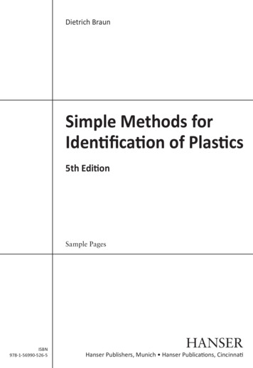
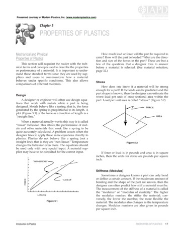
Presented courtesy of Modern Plastics, Inc. (www.modernplastics.com)Chapter 5PROPERTIES OF PLASTICSMechanical and PhysicalProperties of PlasticsThis section will acquaint the reader with the technical terms and concepts used to describe the propertiesor performance of a material. It is important to understand these standard terms since they are used by suppliers and users to communicate how a materialbehaves under specific conditions. This also allowscomparisons of different materials.DesignA designer or engineer will often use design equations that work with metals while a part is beingdesigned. Metals behave like a spring; that is, the forcegenerated by the spring is proportional to its length. Aplot (Figure 5.1) of the force as a function of length is a“straight line.”When a material actually works this way it is called“linear” behavior. This allows the performance of metals and other materials that work like a spring to bequite accurately calculated. A problem occurs when thedesigner tries to apply these same equations directly toplastics. Plastics do not behave like a spring (not astraight line), that is they are “non-linear.” Temperaturechanges the behavior even more. The equations shouldbe used only with very special input. A material supplier may have to be consulted for the correct input.How much load or force will the part be required tocarry? How will the part be loaded? What are the direction and size of the forces in the part? These are but afew of the questions that a designer tries to answerbefore a material is selected. (See material selection,page 32.)StressHow does one know if a material will be strongenough for a part? If the loads can be predicted and thepart shape is known, then the designer can estimate theworst load per unit of cross-sectional area within thepart. Load per unit area is called “stress.” (Figure 5.2)Figure 5.2If force or load is in pounds and area is in squareinches, then the units for stress are pounds per squareinch.Stiffness (Modulus)Figure 5.1Introduction to PlasticsSometimes a designer knows a part can only bendor deflect a certain amount. If the maximum amount ofbending and the shape of the part are known, then thedesigner can often predict how stiff a material must be.The measurement of the stiffness of a material is calledthe “modulus” or “modulus of elasticity.” The higherthe modulus number, the stiffer the material; conversely, the lower the number, the more flexible thematerial. The modulus also changes as the temperaturechanges. Modulus numbers are also given in poundsper square inch.PROPERTIES OF PLASTICS17
TYPICAL TENSILE MODULUS VALUES (PSI)at Room TemperatureGraphic-epoxy composites . . . . . . . . . . . . . . . . . . . . . . 40,000,000Steel . . . . . . . . . . . . . . . . . . . . . . . . . . . . . . . . . . . . . . . 30,000,000Aluminum, 1000 series. . . . . . . . . . . . . . . . . . . . . . . . . 10,000,000Epoxy-glass laminates . . . . . . . . . . . . . . . . . . . . . . . . . . 5,800,000Polyester-glass reinforced . . . . . . . . . . . . . . . . . . . . . . . 2,000,000Nylons, 30% glass reinforced. . . . . . . . . . . . . . . . . . . . . 1,400,000Acrylics . . . . . . . . . . . . . . . . . . . . . . . . . . . . . . . . . . . . . . . 500,000Cast epoxy . . . . . . . . . . . . . . . . . . . . . . . . . . . . . . . . . . . . 450,000Polycarbonate . . . . . . . . . . . . . . . . . . . . . . . . . . . . . . . . . . 450,000Acetal, copolymer . . . . . . . . . . . . . . . . . . . . . . . . . . . . . . . 410,000Polyethylene; high molecular weight . . . . . . . . . . . . . . . . . 100,000StrainThe measurement of how much the part bends orchanges size under load compared to the originaldimension or shape is called “strain.” Strain applies tosmall changes in size.STRAIN (Final Length – Original Length) Original Length Change in Length or Deformation Original LengthIf the change in size is in inches and the originaldimension is in inches, then the units for strain are inchper inch.Stress, strain and modulus are related to each otherby the following equation. The modulus or stiffness of amaterial can be determined when the material is loadedin different ways, such as tension, compression, shear,flexural (bending) or torsion (twisting). They will becalled tensile modulus, also known as plain modulus,flexural modulus or torsional modulus.MODULUS STRESS STRAINTHE PERFORMANCE OF A PLASTIC PARTIS AFFECTED BY: What kind of load the part will see (tensile, impact, fatigue, etc.)How large the load isHow long or often that load will be appliedHow high and/or low a temperature the part will seeHow long it will see those temperaturesThe kind of environment the part will be used in. Will moistureor other chemicals be present?This is where plastics differ in their behavior when compared toother materials, such as metals and ceramics. Choosing stressand/or modulus values that are too high and do not account fortime and temperature effects can lead to failure of the part.Some additional terms that are used to describematerial behavior:Yield PointThe yield point is that point when a material subjected to a load, tensile or compression gives and will nolonger return to its original length or shape when theload is removed. Some materials break before reachinga yield point, for example, some glass-filled nylons ordie cast aluminum.To try to further visualize this property, take a pieceof wire and slightly bend it. It will return to its originalshape when released. Continue to bend and release thewire further and further. Finally, the wire will bend andnot return to its original shape. The point at which itstays bent is the yield point. The yield point is a veryimportant concept because a part is usually useless afterthe material has reached that point.or in other wordsMODULUS Load Change in shape when loaded(STIFFNESS)Choose the type of modulus in the property sheetthat most nearly duplicates what the customer expectsthe major load to be. If the load is unknown, use thelowest moduli value of the two. These numbers can beused for short-term loading if the load is to be appliedfor only a few days at the most.The stress/strain equation is the equation used bydesigners to predict how a part will distort or changesize and shape when loaded. Predicting the stress andstrain within an actual part can become very complex.Fortunately, the material suppliers use tests that areeasy to understand.18PROPERTIES OF PLASTICSTensile StrengthThe maximum strength of a material without breaking when the load is trying to pull it apart is illustratedin Figure 5.3. This is the system used by the suppliers toreport tensile properties in their literature, such asstrength and elongation.A good way to visualize this property is to think ofpulling a fresh marshmallow apart and then pulling apiece of taffy apart. The force or pounds required to pullthe taffy apart would be much greater than required topull the marshmallow apart. If that force is measuredand the taffy and marshmallow each had a cross-sectional area of one square inch, then the taffy has thehigher tensile strength in terms of pounds per squareinch (psi). Plastics may demonstrate tensile strengthsfrom 1,000 psi to 50,000 psi.Introduction to Plastics
Figure 5.3This term becomes less meaningful with some of thesofter materials. PTFE, for example, does not fracture.Consequently, the compressive strength continues toincrease as the sample is deforming more and more. Ameaningful compressive strength would be the maximum force required to deform a material prior to reaching the yield point. The compressive term similar to“elongation” is “compressive deformation,” though it isnot a commonly reported term. It is easy to visualizetwo identical weights, one sitting on a 1" cube of freshmarshmallow and the other on a 1" cube of taffy. Themarshmallow would be flattened and deformed more.ElongationElongation is always associated with tensilestrength because it is the increase in the original lengthat fracture and expressed as a percentage. An examplewould be to pull on a 1" wide piece of paper that is 4"long. It tears with no visible elongation or nearly 0 percent elongation. Now do the same thing to a 1" 4"piece of taffy. It will stretch several times its original 4"length before it fractures. Assume that it is stretched toa 12" length, then (12" 4")(100) 300 percent elongation.Figure 5.6Shear StrengthShear strength is the strength of a material when thematerial is loaded as shown in Figure 5.7. The surfacesof the material are being pulled in opposite directions.Some examples of items that experience shear loadingare the nail holding a picture on the wall, the cleats ofathletic shoes, and tire tread as a car speeds up or slowsdown.Figure 5.4Compressive StrengthCompressive strength is the maximum strength of amaterial without breaking when the material is loadedas shown in Figure 5.5. Check if the material supplierhas the information on compressive strength, since it isnot always determined.Figure 5.7Flexural StrengthFigure 5.5Introduction to PlasticsFlexural strength is the strength of a material whena beam of the material is subjected to bending as shownin Figure 5.8. The material in the top of the beam is incompression (squeezed together), while the bottom ofthe beam is in tension (stretched). Somewhere inbetween the stretching and squeezing there is a placewith no stress and it is called the neutral plane. A simple beam supported at each end and loaded in the mid-PROPERTIES OF PLASTICS19
dle is used to determine the flexural modulus given inproperties tables. Skis, fishing poles, pole vault polesand diving boards are examples of parts needing highflexural strength.Figures 5.11 through 5.15 show the tensile straincurves for different types of materials. Remember tothink of pulling on different kinds of taffy; that is, softand weak, hard and brittle, etc.Figure 5.8Torsional StrengthTorsional strength is the strength of a material whena shape is subjected to a twisting load as shown inFigure 5.9. An example of a part with a torsion load is ascrew as it is being screwed in. The drive shaft on a caralso requires high torsional strength.Figure 5.9Figure 5.11Figure 5.12Poisson’s RatioSometimes a designer will need a value forPoisson’s ratio. This ratio occurs in some of the morecomplex stress/strain equations. It sounds complicated,but it is simply a way of saying how much the material(taffy) necks down or gets thinner in the middle when itis stretched (Figure 5.10). Its value is most often between.3 and .4 for plastic materials. Check supplier literaturefor specific information.Figure 5.13Figure 5.1020PROPERTIES OF PLASTICSIntroduction to Plastics
Figure 5.16 also shows how the material is softerand weaker at higher temperatures. Plastics are alsoaffected by low temperatures and many become morebrittle as the temperature goes down.Figure 5.17 shows the effect of moisture in theatmosphere on the properties of a material like nylon.The dry material is hard and brittle while the wet material is soft and tough. This is like comparing uncookedspaghetti to cooked spaghetti.Figure 5.14Figure 5.17TYPICAL TENSILE YIELD STRENGTHSOF SOME MATERIALS (psi)Figure 5.15Figure 5.16 shows how a plastic material can appearstiffer and stronger if it is pulled apart faster. An example of rate sensitivity is when we cannot pull a stringapart, but we can snap it apart.0.2 in/min0.2 in/minFigure 5.16Introduction to PlasticsLow alloy hardening steels; wrought, quenched andtempered . . . . . . . . . . . . . . . . . . . . . . . . . . . . . . . . . . 288,000High strength low alloy steels; wrought, as-rolled . . . . . . . 80,000Aluminum casting alloys . . . . . . . . . . . . . . . . . . . . . . . . . . . 55,000Aluminum alloys, 1000 series . . . . . . . . . . . . . . . . . . . . . . . 24,000Polyphenylene sulfide, 40% glass reinforced . . . . . . . . . . . 21,000Acetal, copolymer, 25% glass reinforced . . . . . . . . . . . . . . 18,500Nylons, general purpose . . . . . . . . . . . . . . . . . . . . . . . . . . . 12,600Acetal, homopolymer. . . . . . . . . . . . . . . . . . . . . . . . . . . . . . 10,000Acrylics . . . . . . . . . . . . . . . . . . . . . . . . . . . . . . . . . . . . . . . . 10,000Acetal, copolymer . . . . . . . . . . . . . . . . . . . . . . . . . . . . . . . . . 8,800ABS/polycarbonate . . . . . . . . . . . . . . . . . . . . . . . . . . . . . . . . 8,000Polypropylene, general-purpose . . . . . . . . . . . . . . . . . . . . . . 5,200Polypropylene, high-impact . . . . . . . . . . . . . . . . . . . . . . . . . . 4,300CreepVisualize large weights being hung on bars of different materials. All materials will experience some initial and immediate deformation or stretching when theload is first applied. As long as the yield point has notbeen exceeded, a metal sample which acts like a springwill not stretch any more regardless of how long theweight is left on. When the weight is removed, the metalbar will return to its original shape. The length of a plastic bar will continue to slowly increase as long as theload is applied. This is called creep. The amount of creepPROPERTIES OF PLASTICS21
increases as the load and/or temperature are increased.Some thermoplastics like nylons will creep more whenthey have softened because of the presence of moisture.The cross-linked or three-dimensional net structure inthermosets resists creep better than thermoplastics.Reinforcements like glass and carbon, which do notcreep, greatly reduce the creep of the composite material when mixed with a plastic.Since the stress is kept constant and the weight orload is not changed or removed, the equation becomes:Remember the relationship between stress, strainand modulus:The data is sometimes presented in supplier literature in terms of stress relaxation. This means that thestrain is held constant and the decrease in the load(stress) is measured over time. This is called “stressrelaxation.” This information is important for applications, such as gaskets, snap fits, press fits and partsjoined with screws or bolts. The equation becomes:Modulus Stress StrainThe initial strain or change in length with theweight will give a value for the modulus. (This is usually the short term value reported in the property tablesfor the tensile modulus or flexural modulus.) If theweight (stress) is left on over a period of time, theamount of bending or elongation continues to increase,and the value for the modulus will decrease with timeas shown in Figure 5.18. This decreasing modulus that isa function of time (and even temperature) is called the“creep modulus” or “apparent modulus.”This is the modulus that the designer should beusing to more accurately predict the behavior of theplastic materials. The value chosen from the supplier’sliterature will be based on the estimated time the loadwill be applied, the amount of the load, and the temperature conditions present when the load is to be applied.Apparent Modulus StressInitial Strain Creep StrainApparent Modulus Total Strain Constant (Stress)Or, in other words, if the strain goes up, then theapparent modulus must come down. Since the strainincreases with time and temperature, the apparent modulus decreases with time and temperature.Apparent Modulus Stress Constant ( Strain)Or, in other words, as the stress goes down becausethe material moves, then the apparent modulus alsogoes down.Sometimes a supplier will recommend a maximumdesign stress. This has a similar effect to using theapparent modulus. The recommended design stress forsome acrylic injection molded parts is 500 psi, and yetits tensile strength could be reported to be as much as10,000 psi in the property chart. Designers will oftenlook at the 10,000 psi value and cut it in half to be safe.However, it is not really enough, and could lead to failure of the part (Figures 5.19 and 5.20). StressTotal StrainFigure 5.19Figure 5.18CREEP IS AFFECTED BY: Load (Stress) Temperature Length of time the load is applied Other environmentals, such as moisture or chemicals22PROPERTIES OF PLASTICSFigure 5.20Introduction to Plastics
Figure 5.21 shows the tensile elongation of a material as a function of time at various stress levels. Thinkabout pulling a piece of taffy to help visualize what ishappening. The X indicates that the test bar broke.Notice how the elongation is significantly reduced asthe stress level is reduced. A stress level is finallyreached where the creep is nearly negligible. These values will be the stress levels recommended as design criteria.Fatigue StrengthPlastics, as well as other materials subjected tocyclic loading, will fail at stress levels well below theirtensile or compressive strengths. The combination oftension and compression is the most severe condition.This information will be presented in S-N curves ortables. The S-N stands for stress-number of cycles. Apart will survive more cycles if the stress is reduced. Thestress can be reduced by reducing the deflection and/ordecreasing the thickness of a part.Some examples of cyclic loading are a motor valvespring or a washing machine agitator. With time, partsunder cyclic loading will fail. However, properlydesigned and tested they will not fail before several million loadings have been completed.Figure 5.23 shows a typical S-N curve.Figure 5.21Figure 5.22 shows one of the ways the creep data isoften presented in literature. The time scale is usuallyover a very long time, hundreds and more often thousands of hours. Most of the literature will compress thetime scale for ease of reading with the use of a logarithmic scale along that axis.Figure 5.23Impact StrengthFigure 5.22Always check the supplier’s literature for creepdata for a specific material.Introduction to PlasticsMany plastics demonstrate excellent impactstrength. Impact strength is the ability to withstand asuddenly applied load. Toughness is usually used todescribe the material’s ability to withstand an impact orsudden deformation without breaking. No single testhas yet been devised that can predict the impact behavior of a plastic material under the variety of conditionsto which a part can be subjected. Many materials display reduced impact strength as the temperature is lowered. Thermosets and reinforced thermoplastics maychange less with changes in temperature. Check thesupplier literature for any unusual factors that mayaffect the impact performance of a part.Some of the impact tests commonly used in supplierliterature follow.PROPERTIES OF PLASTICS23
Izod Test: designed to measure the effect on toughnesswhen the test specimen is suddenly impacted by aswinging pendulum.Brittleness Temperature Test: determines ability of thematerial to continue to absorb impacts as the temperature is decreased.Special tests may need to be devised to more nearlyduplicate the actual application. Information providedby these tests will aid in choosing material candidates.However, the designer must still test the actual partunder conditions as near as possible to actual use conditions before being confident that the material selectionis adequate.Notch SensitivityFigure 5.24Tensile Impact Test: designed to measure the toughnessof a small specimen without a notch when subjected toa sudden tensile stress or load.Some plastic materials have exceptional impact performance and very good load carrying capability.However, the performance of a material can be greatlyreduced by having sharp corners on the part. The sharpcorners can be part of the design or from machiningoperations. A sharp corner is a great place for a crack tostart. The Izod impact strength of a tough material likepolycarbonate is reduced from 20 to 2 as the radius (R)of the notch is reduced from 0.020" R to 0.005" R respectively.The sharp corners not only reduce the impact resistance of a part, but also allow for a stress concentrationto occur and encourage the premature failure of a loadcarrying part. Minimizing sharp corners may make themachining operation more difficult. However, it may becrucial to the part’s success. Edges of sheet being usedin impact applications like glazing must also be finishedto be free of sharp notches. This is a concern withacrylics and even tough materials like polycarbonate.Figure 5.25Gardner Impact Test: drops a shaped weight and deter-mines the energy required to break the test sample.Figure 5.27Melt IndexFigure 5.2624PROPERTIES OF PLASTICSMelt index determines the internal flow rate of aplastic through a die at a given temperature and load. Inmore common terms this test will tell you how fast theplastic will flow when heated. This will affect how thematerial will process, fill a mold, or flow through a die.Melt index is described in ASTM D1238. A sample ofplastic is charged into a heated cylinder within the meltindex apparatus. A weighted piston is used to push theIntroduction to Plastics
plastic through the cylinder and through a die at theend. The temperature at which a sample is tested is predetermined by the standard for each given polymer.After the cylinder is charged and the weighted piston isin place, the piston is blocked and the plastic is heatedfor six to eight minutes. At that point the block isremoved, and the weighted piston forces the moltenplastic through the die. A sample is collected for a specific time interval (e.g., one minute) and the extrudate ismassed. The melt flow is determined by the followingequation:grams of extrudate———–————— 10 Melt Flow (g/10 min)time in minutesMelt flow is affected by the molecular structure of apolymer. The more complex the molecule, the melt flowwill tend to be lower. If a plastic has polymer moleculesof approximately the same length, the melt flow willtend to be higher. Likewise the plastic that has a mixtureof long and short polymer chains will tend to not flowas well and will result in a lower melt index. Melt indexis also affected by fillers and reinforcements in a plastic.Crystallinity will affect the melt flow of a material. Therange of melt flows can be from 0.5 g/10 min to as muchas 25.0 g/10 min.Specific GravityFor solids and liquids, specific gravity is the ratio ofthe density of a material to the density of water at 4 Cwhich is taken as 1.0 (since one cc of water weighs onegram). For example, a solid or liquid with a density of1.5g/cc has a specific gravity of 1.5/1 or 1.5.tion is the percent swell, which measures the change insurface area of a material. Plastics such as polyethylenehave extremely low water absorption whereas nylonhas a relatively high rate of water absorption.Glass Transition TemperatureGlass transition temperature is the temperatureabove which an amorphous polymer is soft and rubbery. Below the glass transition temperature an amorphous polymer is hard, brittle and glassy.Thermal Properties of PlasticsWith a change in temperature, plastic materials tendto change size considerably more than other materials,such as steel, ceramics and even aluminum. A designermust consider these differences. In fact, the shippingenvironment may expose the part to a much greatertemperature variation than the part will ever see in use.The measure of how much a part changes size as thetemperature changes is called the “thermal coefficient ofexpansion.”Coefficient of ExpansionThe units are usually given in inches per inch perdegree Fahrenheit. It is the change in unit length or volume of a part caused by a unit change in the temperature.TYPICAL COEFFICIENTS OF EXPANSION (IN/IN/F)SPECIFIC GRAVITIES OF SOME COMMON PLASTICS(as measured by ASTM test method D792)ABS . . . . . . . . . . . . . . . . . . . . . . . . . . . . . . . . . . . . . . . . . 1.1 to 1.2Acetal . . . . . . . . . . . . . . . . . . . . . . . . . . . . . . . . . . . . . . . . . . . 1.42Polyethylene (low-density). . . . . . . . . . . . . . . . . . . . . . 0.91 to 0.93Polyethylene (high-density) . . . . . . . . . . . . . . . . . . . . 0.94 to 0.965PVC (rigid). . . . . . . . . . . . . . . . . . . . . . . . . . . . . . . . . . 1.35 to 1.45PVC (flexible) . . . . . . . . . . . . . . . . . . . . . . . . . . . . . . . 1.16 to 1.35Polymethylmethacrylate . . . . . . . . . . . . . . . . . . . . . . . 1.17 to 1.20Polycarbonate . . . . . . . . . . . . . . . . . . . . . . . . . . . . . . . . . . . . . 1.20If the size of a part is known, specific gravity can beused to determine the weight of that part in a variety ofmaterials.Water AbsorptionPolyethylene . . . . . . . . . . . . . . . . . . . . . . . . . . . . . . . . . . 0.000140Acrylics . . . . . . . . . . . . . . . . . . . . . . . . . . . . . . . . . . . . . . 0.000060Acetal, copolymer . . . . . . . . . . . . . . . . . . . . . . . . . . . . . . 0.000047Polycarbonate . . . . . . . . . . . . . . . . . . . . . . . . . . . . . . . . . 0.000037Aluminum, 1000 series . . . . . . . . . . . . . . . . . . . . . . . . . . 0.000013Polycarbonate, 30% glass reinforced . . . . . . . . . . . . . . . 0.000009Steels . . . . . . . . . . . . . . . . . . . . . . . . . . . . . . . . . . . . . . . 0.000008Glass . . . . . . . . . . . . . . . . . . . . . . . . . . . . . . . . . . . . . . . . 0.000004Example: Assuming an acrylic material, how muchwill a 10" dimension change if the temperature changes40 F?The change in length Original length the coefficient of expansion the change in temperature 10 0.00006 40 0.024"Water absorption is the degree of penetration ofwater into the inner structure of another material, suchas plastic. A common measure for the degree of absorp-Introduction to PlasticsPROPERTIES OF PLASTICS25
Deflection Temperature Under LoadElectrical Properties of PlasticsIn addition to changing size, the strength and modulus of elasticity of plastic materials tend to decrease asthe ambient temperature increases. The standard test fordetermining the deflection temperature under load(DTUL) at 66 and 264 psi provides information on theability of a material to carry a load at higher temperatures. The 66 psi means a light load and the 264 psimeans a heavy load on a beam. The temperature of theloaded beam is raised until a certain amount of deflection is observed. The temperature when that deflectionis reached is called the DTUL. Plastics usually have ahigher DTUL at 66 psi than 264 psi because of the lowerload.Commercial plastics are generally very good electrical insulators and offer freedom of design in electricalproducts. Electrical properties may also be changed byenvironmental conditions, such as moisture and/ortemperature.Note: The DTUL is sometimes referred to as the heatdistortion temperature or HDT.A basic concept to remember is that electrons mustbe exchanged between molecules for electric current toflow through a material. Plastic molecules hold on totheir electrons and do not permit the electrons to floweasily; thus, plastics are insulators.Plastics containing oxygen and nitrogen moleculesare “polar” which means that they will tend to act likelittle magnets and align themselves in the presence of avoltage or field, the same as the needle in a compass trying to point north. Plastics not containing oxygen andnitrogen molecules such as polyethylene, polypropylene and polystyrene are nonpolar.The electrical properties of plastics are usuallydescribed by the following properties:Volume ResistivityFigure 5.28TYPICAL DEFLECTION TEMPERATURES,LOADED TO 264 PSI (F)Silicone materials . . . . . . . . . . . . . . . . . . . . . . . . . . . . . . . . . . . 850Nylon, 30% glass reinforced . . . . . . . . . . . . . . . . . . . . . . . . . . 495Epoxy, mineral, glass reinforced. . . . . . . . . . . . . . . . . . . . . . . . 400Acetal, glass reinforced . . . . . . . . . . . . . . . . . . . . . . . . . . . . . . 325Polycarbonate. . . . . . . . . . . . . . . . . . . . . . . . . . . . . . . . . . . . . . 295Nylon, general-purpose . . . . . . . . . . . . . . . . . . . . . . . . . . . . . . 220Acrylic. . . . . . . . . . . . . . . . . . . . . . . . . . . . . . . . . . . . . . . . . . . . 180Propylene, general-purpose . . . . . . . . . . . . . . . . . . . . . . . . . . . 140Impact strength is also affected by changes in temperature in most plastic materials. The changes instrength can be significant, especially as the temperature is lowered. Check the supplier literature carefully.Thermal ConductivityMany plastics are good thermal insulators; that is,heat does not travel through them easily. We experiencethis every time we pick up a hot pan by its plastic handle. The “conductivity” of plastics is 300 to 2,500 timesless than most metals. This property shows why it takesa long time for a casting or other molded parts to cooldown in the middle. Internal stress can be set up in amaterial because of the differences in the cooling ratesbetween the outside of a part and the core.26PROPERTIES OF PLASTICSVolume resistivity is defined as the ratio betweenthe voltage (direct current or DC), which is like the voltage supplied by a battery, and that portion of currentwhich flows through a specific volume of the specimen.Units are generally ohm per cubic centimeter.Visualize putting DC electrodes on opposite faces ofa one centimeter (.394 inch) cube of a plastic material.When a voltage is applied, some current will flow intime as the molecules align themselves (Figure 5.29).Figure 5.29Ohm’s Law tells us that the voltage (volts) dividedby the current (amps) is equal to a resistance (ohms) orV/I R. When the voltage applied to the cube isdivided by the current, the resistance for 1 cm of theplastic is determined, or ohm per cm.Generally, plastics are naturally good insulators andhave very high resistance. The volume resistivity canchange with temperature and the presence of moistureor humidity.Introduction to Plastics
Surface ResistivityThe surface resistivity is the ratio between the directcurrent (DC) and current along the surface per unitwidth. Units are generally ohms.Frequency may also affect this property when the material is subjected t
stiffer and stronger if it is pulled apart faster. An exam-ple of rate sensitivity is when we cannot pull a string apart, but we can snap it apart. Figure 5.16. Figure 5.16 also shows how the material is softer and weaker at higher temperatures. Plastics are also affected by low temperatures and many become more brittle as the temperature goes .