Transcription
Journal oticema sthhysical MafPJournal of Physical MathematicsFandem, J Phys Math 2017, 8:2DOI: 10.4172/2090-0902.1000221ISSN: 2090-0902ResearchArticleResearchArticleOpen AccessFailure of Mechanical Equipment Due to Welding ImperfectionsFandem QA*Aramco, Qatif, Eastern Region, Saudi ArabiaAbstractEach of welding processes has some disadvantages and limitations; For instance existence of weldingimperfections that might be due to poor workmanship or design issues such as cracks, porosity, lack of fusion,incomplete penetration, spatters and others. Failure of Schenectady T2 tanker in 1943 is a good example of brittlefracture where the crack initiated due to presence of notches in steels that are sensitive at low temperature.Keywords: Welding; Microstructure; Base metalIntroductionWelding is one of the most important techniques of joining metalshomogenously in refinery and petrochemical industry with variousgeometries and sizes in low overall cost. There are several types ofwelding process such as Shielded Metal Arc Welding (SMAW), GasTungsten Arc Welding (GTAW) etc. The objective of this paper isto provide an overview of the main weldment defects in mechanicalequipment (pressure vessels, pipes, and tanks), detection of thesedefects using Non Destructive Testing (NDT) methods and how theseimperfections may lead to cracks initiation and hence a fracture occurs.This report will also show Engineering Critical Assessment used toevaluate cracks exist in mechanical equipment that is on operation.Main Welding Defects in Mechanical EquipmentThere are about 26 types of welding defects for different weldingprocesses and for different weld joint design per ISO 5817. These defectscould be on the surface of the weld, inside the weld, in the root pass oreven on the base metal close to the welding area like heat affected zone(HAZ), portion of the base metallurgy whose mechanical propertiesor microstructure have been altered by the heat of welding per API577. Figure 1a shows the different types of welding defects in butt andfillet weld joints. Examples of on the surface defects arc strike, undercutand spatters, which are a molten metal splashed over the surface due tohigh welding current used as shown in Figure 1b. Examples of defectsinside the weld are porosity, slag inclusions, lack of fusion etc. Porosityis entrapped hydrogen or oxygen gas inside the weld due to insufficientshielding from the electrode flux, while slag inclusion is de-oxidationproduct from welding flux. Moreover, lack of fusion is poor adhesionbetween the weld and base metal due to incorrect welding setting ordesign. Figures1c and 1d show these defects. On the other hand, cracksmay exist on the weld or between weld-base metal during solidificationor after cooling 'delayed cracking' as shown in Figure 1e [1,2].Non-Destructive Testing (NDT) TechniquesIn order to check the soundness of the weld for the equipmentwithout damaging or destroying it, the manufacturers or fabricatorsare using NDT methods. There are several types of these such asPenetrant Testing, Radiographic Testing (RT), Ultrasonic Testing(UT), Magnetic Testing (MT) and of course Visual Testing (VT). Thereare also advanced NDT techniques used for welding critical servicessuch as Time of Flight Diffraction Ultrasonic (TOFD). Some of thesemethods will be discussed briefly in this report.Penetrant Testing is simple and low cost technique used to detectopen to surface defects such as crack by using three different sprayersJ Phys Math, an open access journalISSN: 2090-0902i.e., penetrant, developer and cleaner sprayers. The applying procedureof this method is by cleaning the surface and applies the penetrantwhich is in red color, and then after five minutes the area cleaned offwith use of the cleaner followed by applying the developer which isin white color to bleed out the penetrant and make a color contrast.The crack will be visible easily after application as in Figure 2. Thedisadvantages of this method are; used only for open to surface defects,temperature limit of 125 F maximum, cannot be used to measure flawsize [3,4] (Figure 2).Another NDT method is Ultrasonic Testing which is a manual andeffective to measure the defect size as well as detect internal defectsin the weld by sending a beam of sound waves with frequency range( 20,000 cycles per second). If there is any defect the waves will bereflected back to the probe and amplitude intensity displayed on thescreen. The disadvantages are requiring certified operator, even withthe certified personnel it is difficult to recognize the type of weldingdefect and no permanent record of the measured defects [3,4].Radiographic Testing is one of the most effective techniques usedto detect internal defects by sending X-rays from radioactive source (Ir192 or Cobalt 60) placed at one side of the weld and on the other sidean image film is placed with image quality indicator (IQI). The maindisadvantages of this method are health hazardous, high cost and verysensitive to the defect orientation for example if there is a crack parallelto the X-rays as shown in Figure 3, it appears on the film as a dot andthe interpreter will recognize it as porosity instead of the crack, thatis why it is not recommended to use RT for crack detection or to beused at several different shooting angles at the same joints which meansmore cost [3,4].After completion of the NDT methods ASME & API standardsmandate testing the entire piping system or hydrocarbon plant byhydrostatic test. This is considered as the last line of defense beforeturning in the plant for operation to make sure it will operate safelywithout failure. This test can be performed with use of clean water with*Corresponding author: Fandem QA, Aramco, Qatif, Eastern Region, SaudiArabia, Tel: 7 836 245-53-44; E-mail: q 2010@hotmail.comReceived March 13, 2017; Accepted April 13, 2017; Published April 20, 2017Citation: Fandem QA (2017) Failure of Mechanical Equipment Due to WeldingImperfections. J Phys Math 8: 221. doi: 10.4172/2090-0902.1000221Copyright: 2017 Fandem QA. This is an open-access article distributed underthe terms of the Creative Commons Attribution License, which permits unrestricteduse, distribution, and reproduction in any medium, provided the original author andsource are credited.Volume 8 Issue 2 1000221
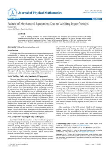
Citation: Fandem QA (2017) Failure of Mechanical Equipment Due to Welding Imperfections. J Phys Math 8: 221. doi: 10.4172/2090-0902.1000221Page 2 of 6abcwww.esabna.com/us/en/educationPorositiesdeA solidification crack in a weld faceFigure 1: (a). Different types of welding defects in butt weld (left) and fillet weld (right) [2]. (b). Spatters over weld and base metal; (c). Porosities inside a filletweld. (d). Lack of fusion and slag in butt weld [3]; (e). Solidification crack on the weld face.Sourcecrack parallel to thex-ray exposurecrack on the RT filmFilmFigure 2: Crack is visible after applying the three sprayers.specific PH based on the material and other requirements that mustbe followed in the codes at pressure of 1.5 design pressures but shallnot exceed 0.9 of the yield strength. In case of a serious defect exists inthe weld that was not discovered by other NDT methods, a failure willoccur as shown in Figure 4. As alternative where water cannot be used,a pneumatic test is performed with use of air at pressure of 1.1 designJ Phys Math, an open access journalISSN: 2090-0902Figure 3: Sensitivity of RT to the crack orientation, the crack appears asporosity on the film [4].pressure, but this is rarely done because of high stored energy that leadsto a disaster in case of failure.Welding Imperfections and Their Effect on FractureSome welding defects can be considered as fracture cause from theVolume 8 Issue 2 1000221
Citation: Fandem QA (2017) Failure of Mechanical Equipment Due to Welding Imperfections. J Phys Math 8: 221. doi: 10.4172/2090-0902.1000221Page 3 of 6first stage such as cracks. Moreover, in terms of fracture mechanics lackof fusion and lack of penetration are also considered are long cracksthat contribute to the crack driving force against the resistance of thematerial to crack propagation as shown in Figure 5a [5].Furthermore, other defects which might cause crack initiation suchas slag inclusions and spatters. For the spatters, due to difference intemperature with the hit surface there will be a local restrain whichcauses a tensile residual stresses in the droplets and hence the impuritieswill act as crack initiation as show in Figure 5b [6].On the other hand, there are defects may not cause crack initiationdepend on the location of the defect in weld such as porosity. Forinstance, surface porosity may have an effect of fracture that dependson its volumetric size; the strength of the weld is influenced as well.Therefore, the welding defects can be classified into three categories asfollows [7]: Crack and crack like imperfections such as lack of fusion whichcause a fracture and must be avoided. Imperfections act as crack initiation sites due to its geometry orsharp edges which cause the stress concentration and increasein the residual stress during solidification such as spatters,angular misalignment, slag inclusions, undercut and weld toe.Consequently, this type of defects may initiate fatigue crackduring service.Figure 4: Two failures occurred during hydro test due to existence of weldingdefects.abFigure 5: (a). Lack of fusion is considered as long crack [6]; (b). Spatter causescrack initiation [2]. Imperfection which does not have any effect of fracture andfatigue life such as porosity due to its round shape geometrywithout having sharp edges and hence no stress concentration.Harrison proved using fatigue data of porosity that the severityof the porosity could be evaluated by only one factor which isthe volume of defect and test the results revealed similar fatiguestrength [8].Acceptance Criteria of Welding ImperfectionsThe discovered welding defect using NDT methods should beevaluated to identify whether within the acceptable limits or not. EachNDT method has different criteria in the construction and in servicecodes of pressure vessels, storage tanks and piping i.e., ASME-VIIIfor pressure vessels, ASME-B31.3 for piping and API-650 for storagetanks. Some of the acceptance criteria from codes are listed in Table1 [9-11].Assessment of Welding Imperfections in Terms ofFracture MechanicsSometimes the design and material properties fall outside thescope of the construction codes or a flaw that is beyond acceptancecode limit is found in mechanical equipment already placed in service.In this case fracture mechanics approach is required for evaluation i.e.,Engineering Critical Assessments (ECA) methods, such as BS7910, R6,Fitness for Service Network (FITNET) and API 579-1/ASME FFS-1.The most common method used in refinery and hydrocarbon plants isAPI 579. It was first published in 2000 in USA to evaluate discoveredflaws or damage in in operation mechanical equipment to decide ifthe equipment will continue in operation safely without failure till therepaired performed. This code is considered as a supplementary toASME B31.3, API 650, ASME VIII and API 570. Section 9 from API 579(FFS) is used for assessment of crack like imperfections in welds whichwill be discussed in detail. This method depends on Failure AssessmentDiagram (FAD) for flaws evaluation by calculating Toughness ratio Krand load ratio Lr and then the point coordinate plot on to determinethe acceptability for continue in service if it is on or below the curve asshown in Figure 6 [12,13].There are three level of assessments in section 9 based on theconservatively and the amount of information required; level-1which is a basic level that require a minimum inspection and can beconducted by an engineer or inspector, to the most advance level, i.e.,level-3 which is performed for most detail evaluation and requires verydetailed inspection as well as analysis is based on numerical techniquessuch as the finite element method and it must be done by engineersof at least two years' experience in FFS. The assessment steps will bediscussed through a case study from API 579 [13].Type of DefectPiping (ASME B31.3)Pressure Vessel (ASME Sec. VIII)SpatterNot acceptableNot acceptableTanks ( API 650)Not acceptableCrackNot acceptableNot acceptableNot acceptablePorosity1 4t, or 5 32 in. (4 mm), whichever is smaller1 4t, or 5 32 in. (4 mm), whichever is smaller1 4t, or 5 32 in. (4 mm), whicheveris smallerIncomplete penetrationand lack of fusionNot acceptableNot acceptableVertical not permitted HorizontalMax 10%tSlag InclusionL t /3, W 2.5 mm (3 32 in.) and t /3cumulative L t in any 12t weld length2/3 T, T is thickness of platemax T in length of 6THollow BeadNot ListedNot ListedNot ListedTable 1: Examples of welding acceptance criteria for RT method [9,10,11].J Phys Math, an open access journalISSN: 2090-0902Volume 8 Issue 2 1000221
Citation: Fandem QA (2017) Failure of Mechanical Equipment Due to Welding Imperfections. J Phys Math 8: 221. doi: 10.4172/2090-0902.1000221Page 4 of 6Flaw DimensionsStress AnalysisStress Intensity FactorSolution, KIMaterial Toughness,KMATKr KIKMATFailure AssessmentDiagram EnvelopeTOUGHNESS RATIOBrittle FractureUnacceptableRegionMixed Mode - BrittleFracture And tic CollapseLOAD RATIOLr σrefσysReference StressSolution, σrefMaterial Yeild Stress, σysStress AnalysisFlaw DimensionsFigure 6: Lack of fusion is considered as long crack [13].Case StudyInspection dataA crack was discovered during routine inspection in the externalcircumferential weld of 20 in in plant pipe which was constructed perASME B31.3 [13].Level-1 assessment was used and found not satisfactory, henceLevel-2 assessment will be used for evaluation.Step-1 Collect pipe data, operating conditions and inspection dataUsing UT method the crack was measured at depth of 3 mm locatedat external circumferential surface of the weld.Step-2 Calculate stress ratio Lr for both primary stress (pressure)and secondary stress (residual) by first calculating stress reference σf.For primary stress by using Net Section Axial Force and BendingMoment (KCSCCL1)Pipe Data:Ro D/2 508.00/2 254.00 mm (pipe radius) Material SA-106 Grade B Year 2003Ri Ro t 254.00 9.53 244.47 mm (internal pipe radius) Design Conditions 3.0 MPa at 250 CM/π (Ro4 Ri4) (36.8) (10)6/π{(254.00) 4 (244.47) 4} 0.01984N/mm3. Fluid Density 0.8The membrane and bending components for primary stress are Pipe Outside Diameter 508 mm (NPS 20) Pipe Thickness 9.53 mm (Schedule 20) Uniform Metal Loss 0.0 mm FC 0.0 mm Weld Joint Efficiency 1.0 PWHT NoOperating conditions P 2 MPa T 20 C.J Phys Math, an open access journalISSN: 2090-0902 Pm PbgpRi23 244.47 2 37.75Mpa22R0 Ri 2542 244.47 2M π ( R04 Ri4 )Ro 20.2 Mpa0.25Also Partial Safety Factor (PSF) needs to be determined 1.5So Pm 1.5 x 37.75 56.62 Mpa and Pbg 30.3 MpaMrM2 N r2 r24Pσ ref 3π ( R04 Ri2 ) M r P 23.65Mpabg316[ Ro ( Ro a ) Ri4 ]Volume 8 Issue 2 1000221
Citation: Fandem QA (2017) Failure of Mechanical Equipment Due to Welding Imperfections. J Phys Math 8: 221. doi: 10.4172/2090-0902.1000221Page 5 of 6MrM2 N r2 r 95.8Mpa242 72 722 9 1.45 x92.9 (1 0.3) α 93.2 Mpa2 310.3()pσ ref 95.8 Lrp 0.399 where 𝜎ys is yield stress from the same codeSRα refσ ys 24093.2 LSR 0.388rFor secondary stressα ys240σ refp 2SRrefThe membrane and bending components for secondary stress areStep-3 Calculating stress intensity factor σ 1 σ 2 9σ 3 6σ 4 and Qb Qm σ 0 2220152345The stresses represent residual stress distribution over the thicknessand can be determined from best fit fourth polynomial by generatinggraph using (Figure 7)234x x x x σ R ( x) σ 0 σ 1 σ 2 σ 3 σ 4 t t t t Therefore;σ1σ2σ3σ4𝜎0 231𝜎1 608.8For primary stress a P K G0 (σ 0 pc ) G1σ 1 π aI t σ mp σ bp and σ σWhere σ 0components for stress intensity factor.membrane and bending pRi2 M ( R0 Ri ) 2σ mp 57.5MPa multiply by PSF 22 44 R0 R1 π ( R0 R1 ) (1.5) 86.2 MPaM ( R0 Ri ) σ bp 2 0.37 MPa multiply by PSF (1.5) 0.56 MPaπ ( R04 R14 )𝜎2 2806.8𝜎3 8474.7 σ0 86.8 MPa and σ1 1.12 MPa𝜎4 5084.2By substitutionG0 and G1 from Appendix A 1.576 and 0.845 respectively𝜎 Qm 92.9 MPa and Qb 72 MpaBy substituting the values in K PI , the K PI 13.3MPa mmSRσ ref For secondary stressQb Qb2 9[ Z Qm (1 α ) 2 ]2The stress intensity factor can be calculated using3(1 α ) 2234 a a a a SRK G0 (σ 0 pc ) G1σ 1 G2σ 2 G3σ 3 G4σ 4 aπI t t t t t9.53 τ 0.037R0 508Where G0, G1, G2, G3 and G4 from Appendix A 1.576, 0.845, 0.603,0.478t9.53 τ 0.037R0 508And 0.4189 respectively. And by substituting for the residualstresses; 1 2 2τ ατ Z 1 α 1.45 2 τ K ISR 13.6Mpa mmMPaPolynomialRegressions350300250s r200deg 4deg 3150deg 2deg 1100500-50-1001.00.90.80.70.60.50.40.30.20.10.0ID ODFigure 7: Through wall residual stress distribution [13].J Phys Math, an open access journalISSN: 2090-0902Volume 8 Issue 2 1000221
Citation: Fandem QA (2017) Failure of Mechanical Equipment Due to Welding Imperfections. J Phys Math 8: 221. doi: 10.4172/2090-0902.1000221Page 6 of 6Type of DiscontinuityWelding ProcessesTypical NDEPractical SolutionLack of fusion (LOF)AllUTProper heat input, proper welding technique.Incomplete PenetrationAllRT, UT, VTProper heat input, proper joint design.Slag InclusionSMAW, FCAW,SAWRT, UTProper welding technique, cleaning, avoid excessive weaving.PorosityAllRT, UTLow hydrogen, low sulfur environment, proper shielding.Table 2: Practical solution to prevent reoccurrence.So, the assessment point is below the curve, hence the pipe willcontinue in service safely till next inspection for repair. If the assessmentpoint on or above the curve, level-3 assessment will be 0.81.0LrAssessment Curve1.21.41.61.82.0Assessment PointFigure 8: The assessment point on the FAD [13].Step-4 Fracture toughnessThis report reveals that the critical welding defects leads tocrack initiation and as a consequence fracture failure might occur.As a recommendation to reduce the residual stress in the weld is byperforming post weld heat treatment. Moreover, proper joint designto eliminate sharp edges and hence high stress concentration is alsorecommended. Furthermore, the best way to prevent the defects fromoccurring by following the welding essential variables listed in approvedwelding procedure specification per ASME XI as well as following thepractical solution to prevent reoccurrence as mentioned (Table 2).References1. Hayes B (1996) Classic brittle failures in large welded structures. EngineeringFailure Analysis 3: 2.2. 50th Annual Conference of the British Institute of Non-Destructive Testing, 1315 Sept. 2011. Telford, UK. Web.KIC 36.5 3.084 exp[0.036 (T Tref 56)]Tref from Appendix A for curve B carbon Steel and σys 240 MPa;3. API Standard. Welding Inspection and Metallurgy API 577, American PetroleumInstitute. Washington, 2004.Tref 10C4. ASME Standard. Nondestructive Examination ASME V. The American Societyof Mechanical Engineering. New York, 2007. K IC 69.7 MPa mmeanStep-5 Calculate the mean fracture toughness K matK meanThe ratio of mat can be calculated from Appendix B usingK ICmeanK mat1, at sigma 1 K ICB0 B1 T B2 T 2 B3 T 3 B4 T 4 B5 T 5and ΔT 20 10 10C7. ISO 5817:1992 (2003) Arc welded joints in steel- Guidance on quality levels forimperfections. Geneva: International Organization for Standardization.8. Harrison JD (1972) The basis for a proposed acceptance standard for welddefects, Metal Construction and British Welding J, Part 1: Porosity.10. ASME Standard. Process Piping Code Section B31.3,Chapter VI Inspection,Examination, and Testing. The American Society of Mechanical Engineering.New York.meanK mat 1.6 x69.7 111.52 MPa mStep-6 calculates the toughness ratio Kr11. API Standard (2008) Welded Steel Tanks for Oil Storage API 650, AmericanPetroleum Institute. Washington,.K IP Φ K ISRK matPrSRrBy using Appendix C with L 0.399 and L 0.388ψ 0.029 So6. Zerbst U, Ainsworth RA, Beier HTh, Klingbeil D (2014) Review on Fractureand Crack Propagation in Weldments – A Fracture Mechanics Perspective.Engineering Fracture Mechanics 132: 200-276.9. ASME Standard. Boiler and Pressure Vessel Code Section VIII, Rules forConstruction of Pressure Vessels. The American Society of MechanicalEngineering. New York, 2008.meanK mat1 1.6K IC0.6252Kr 5. Analysis of A Fractured Crane Frame Weldment. Metallurgical Technologies,Inc. Web.Φψ 1 1.071Φoφ12. Macdonald KA (2011) Fracture and Fatigue of Welded Joints and Structures,(1st edn.), Woodhead.13. API Standard (2007) Fitness For Service API 579, American PetroleumInstitute, (2nd edn.),Washington,φ 0.405K IP Φ K ISR 13.3 1.071x13,6 0.2498K mat111.52 KrStep-7 Plot the assessment point in FAD( L , K ) ( 0.399,0.2498) (Figure 8)PrrJ Phys Math, an open access journalISSN: 2090-0902Volume 8 Issue 2 1000221
Different types of welding defects in butt weld (left) and fillet weld (right) [2]. (b). Spatters over weld and base metal; (c). Porosities inside a fillet weld. (d). Lack of fusion and slag in butt weld [3]; (e). Solidification crack on the weld face. Figure 2: Crack is visible after applying the three sprayers. crack parallel to the x-ray .
