Transcription
356IEEE TRANSACTIONS ON POWER ELECTRONICS, VOL. 18, NO. 1, JANUARY 2003Architecture and IC Implementation of a DigitalVRM ControllerAngel V. Peterchev, Student Member, IEEE, Jinwen Xiao, Student Member, IEEE, and Seth R. Sanders, Member, IEEEAbstract—This paper develops the architecture of a digitalPWM controller for application in multiphase voltage regulationmodules (VRMs). In this context, passive current sharing andVRM transient response with nonzero controller delay are analyzed. A scheme for sensing a combination of the VRM outputvoltage and output current with a single low-resolution windowanalog-to-digital converter (ADC) is proposed. The architectureand IC implementation of a digital PWM (DPWM) generationmodule, using a ring-oscillator-multiplexer scheme, is discussed.Experimental results from a prototype VRM and a partialcontroller IC implementation are presented.Index Terms—Analog-digital conversion, current sharing,digital control, digital modulation, inductance, integrated circuits,power conversion, pulse-width modulation, ring oscillators,transient analysis, voltage control.I. INTRODUCTIONDIGITAL controllers are a strong candidate for use involtage regulation modules (VRMs) due to their low quiescent power, immunity to analog component variations, easeof integration with other digital systems, ability to implementsophisticated control schemes, and potentially faster designprocess [1]–[12]. In particular, the ability of digital controllersto accurately match multiple pulse-width modulation (PWM)signals, may allow for the use of passive current sharingschemes in multiphase VRMs, thus reducing the units’ costand complexity. Further, the ease of interface between a digitalcontroller and other digital hardware can be advantageous inmicroprocessor and communication systems. In addition, thelow power dissipation of digital controllers makes them anattractive choice for portable applications.In this paper we develop an architecture for a digital VRMcontroller and discuss aspects of its integrated circuit (IC)implementation. In Section II we start with a brief overviewof the structure of a digitally controlled multiphase VRM.In Section III we analyze passive current sharing, and deriveestimates for the possible phase current mismatch due topower train parameter variations. In Section IV we discuss theVRM transient response with nonzero controller delay, andintroduce an implementation of optimal voltage positioningwith a digital controller. We then propose a low resolutionManuscript received January 10, 2002; revised October 1, 2002. The originalversion of this work was presented at the Power Electronics Specialists Conference (PESC), Vancouver, BC, Canada, June 17–22, 2001. Recommended byAssociate Editor S. B. Leeb.The authors are with the Department of Electrical Engineering andComputer Science, University of California, Berkeley, CA .berkeley.edu;sanders@eecs.berkeley.edu).Digital Object Identifier 10.1109/TPEL.2002.807099analog-to-digital converter (ADC) topology that can be usedin the VRM. Results from a prototype VRM are presented.Section V addresses the architecture of digital PWM (DPWM)generation modules. We discuss the IC implementation of aring-oscillator-MUX DPWM scheme, and present test chipdata. Finally, in Section VI we overview the architecture of acomplete IC implementation of a digital VRM controller.II. OVERVIEW OF A DIGITALLY CONTROLLEDMULTIPHASE VRMA block diagram of a digitally controlled 4-phase buckVRM is shown in Fig. 1. A controller with similar structurehas been discussed in [2]. The controller consists of an ADCwhich converts the regulated quantity (typically a combiand the output current ),nation of the output voltagea discrete-time control law which calculates the duty cyclecommand from the output of the ADC and a digital referenceword [typically a voltage identification code (VID) supplied bya microprocessor], and a DPWM module which generates thegating signals for the power train switches. The four phases areout of phase which reduces the outputswitchedvoltage ripple and the input current ripple, and can improve thetransient response of the converter.III. PASSIVE CURRENT SHARING IN A DIGITALLY CONTROLLEDMULTIPHASE VRMIn general, like analog controllers, digital controllers formultiphase VRMs can be used successfully with active currentsharing schemes, typically involving individual current sensingof each phase. However, unlike their analog counterparts, digital controllers have the advantage of almost perfect matchingof the duty cycles of the PWM signals among the differentphases, potentially allowing for the use of passive currentsharing schemes, which eliminates the need for individualsensing and control of the phase currents. The use of passivecurrent sharing may reduce the cost of the VRM, as a result ofthe smaller number of current sensors needed, as well as thereduced pin count of the controller IC.To study the dc current sharing among the different phases ina -phase converter we model the latter with the circuit shownmodel the dc resistance ofin Fig. 2. Resistorsmodel theeach phase of the power train, andaverage open-circuit voltage for each phase(1)is the duty cycle command for phase , andwherethe input voltage.0885-8993/03 17.00 2003 IEEEis
PETERCHEV et al.: ARCHITECTURE AND IC IMPLEMENTATION OF A DIGITAL VRM CONTROLLER357A. Phase Current Mismatch Due to Power Train ResistanceMismatchFig. 1.As it was argued above, if the multiphase converter hasmatched duty cycles but mismatched power train resistancesamong the phases, the output current distributes itself amongthe phases so as to minimize the power dissipation in the powertrain. However, the actual current mismatch is still of interestsince it may have undesirable consequences such as possiblesaturation of the inductors.Assume matched duty cycles among the phases,. Then, a power train resistance mismatchresults in worst case current mismatch through a particular phase (let this be phase ) when all other phases have thesame power train resistance equal to , while that phase has. Since the power trainmismatched resistanceresistances of the different phases form a current divider for theoutput current , the current through phase isBlock diagram of a digitally controlled multiphase VRM.(4)Then, the mismatch current flowing in phase is the difference,between current and the nominal phase current(5)Hence, the worst case phase current variation due to a power, istrain resistance mismatchFig. 2. DC current sharing model of a k -phase converter.Withhaving arbitrary and possibly mismatched values, as a result of power train mismatches amongthe phases, total power dissipation of the system is minimized. To see this, considerwhen(6)Finally, the value of the effective power train resistance foreach phase can be estimated from(7)(2)which is the total dc power loss in the power train with the constraint that, the sum of the individual phase currents must equalthe total load current, appended with Lagrange multiplier . Anecessary condition for a minimum of the total power loss subject to the constraint is that all first order partial derivatives ofin (2) are zero. This yields(3)for each index corresponding to each phase of the converter.for allThe constraint (3) implies that the dc voltage dropsphases are equal, which is equivalent to the power optimalitystated above.conditionThe above result implies that when the duty cycles appliedto different phases are identical, the power loss is minimized regardless of the possible resistive mismatch among the phases. Adigital controller can produce accurately matched PWM waveforms for the different phases, with possible timing mismatchresulting only from parameter variations of the power FETs andgate drives, which is discussed in Section III-B.is the duty cycle;andare thewhereon-resistances of the high- and low-side MOSFET switches, reis the inductor dc resistance; andis thespectively;resistance of the printed circuit board traces in the power trainfor each phase. The relative variations of these parameters canbe obtained from the data sheet for a particular process, and (7)can be used in conjunction with (6) to estimate the total currentmismatch due to power train resistance mismatch.B. Phase Current Mismatch Due to Duty Cycle Mismatch.Consider again Fig. 2 and letare not equal as a reHowever, assume thatsult of duty cycle mismatch among the phases. A duty cycleresults in worst case current mismatch throughmismatcha particular phase (let this be phase ) when all other phasesare switched with the same duty cycle , while that phase is, i.e.,switched with a mismatched duty cycle. The mismatch current through phase ,, is then(8)
358IEEE TRANSACTIONS ON POWER ELECTRONICS, VOL. 18, NO. 1, JANUARY 2003The dc conduction power loss in the multiphase part of the, and the converter input powerpower train is. Then the dc conduction efficiency of theismultiphase part of the converter power train is(9)Solving (9) for and substituting in (8), we obtain an expresdue to asion for the worst case phase current variation,duty cycle mismatch(10)Fig. 3. Duty cycle variation due to the MOSFET switching characteristic incontinuous conduction mode.One immediate observation from (10) is that the current mismatch sensitivity becomes worse if the efficiency of the converter improves, or if the duty cycle decreases.C. Duty Cycle Mismatch due to MOSFET Switching ParameterVariationsA digital PWM controller can provide very accuratematching among the duty cycles for the different phases, thusthe main source of duty cycle mismatch are the analog gatedrives and power switches. Fig. 3 shows a simplified model ofthe switching characteristic of a MOSFET which determinesthe relation between the duty cycle output by the controller ( )and the effective duty cycle seen at the switching node of the). The gate drive of the MOSFET is modeledpower train (and maximumas a current source with output current. Letanddenote respectively theoutput voltagetransistor gate–source and gate–drain capacitances, and letsubscripts sat and lin refer respectively to the saturation andlinear regions of operation of the MOSFET.) theIn the beginning of the switching period (into the high-side MOSFET gate,gate drive sources currentramp up at a rate of approxmaking its gate-source voltage. Drain-source voltageimatelyremains at the supply voltageuntil the drain currentreaches the value of the output current . Thenplateaus at(11)is the device gain factor and we assume thatwhere. While,moves down at a rate ofuntil the transistor goes into the linear region.continues to increase at a rateThenuntil it reaches. In the linear regionis about. The MOSFET turn-off is analogous.From Fig. 3 it can be seen that the effective duty cycle, mea, issured between the midpoints in the swing of(12)where, for simplicity, we have setdue to perturbations ofvariation ofand. Then theis(13)and(14)is close to, (14) has small contributionSince typicallyvariation relative to (13), and its effect mayto the overallbe neglected. Then, (13) can be used in conjunction with (10)to estimate current variation among phases due to duty cyclemismatch.D. A Passive Current Sharing Calculation ExampleGiven a certain specification on the maximum tolerablecurrent mismatch among the phases of a multiphase converter), the equations developed above can be used to(estimate converter parameters such as the maximum allowable), and totalpower MOSFET gate rise/fall time ().power train resistive mismatch among the phases (Equations (6), (10), and (13) were used to derive the constraintsin Table I based on a sample converter design. Finally, it shouldbe noted again that, while the possible 20% phase currentmismatch due to duty cycle mismatch may result in nonoptimalpower dissipation, the 20% current mismatch due to resistivemismatch will not degrade the converter efficiency. In thisexample, it is seen that a modest gate drive rise/fall time of13 ns leads to quite acceptable current-sharing behavior.Experimental results supporting the feasibility of open-loopcurrent sharing are presented in Section IV-C, as well as in[13].IV. OUTPUT SENSING AND ANALOG-TO-DIGITAL CONVERSIONThe precision with which a digital controller positions theoutput voltage is determined by the resolution of the ADC. Incan be regulated with a precision of oneofparticular,the ADC. Applications such as modern microprocessor VRMsrequire regulation precision of about 10 mV [14], demandingADC modules with very high resolution. For example, regulaV corresponds to ADCtion resolution of 10 mV atVmVb. Further,resolution ofmicroprocessor VRM designs target switching frequencies inthe megahertz range, implying ADC conversion times of lessthan a microsecond. The need for high resolution and fast conversion time may result in expensive and high-power ADC de-
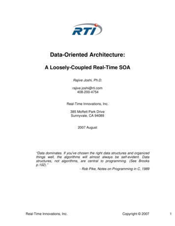
PETERCHEV et al.: ARCHITECTURE AND IC IMPLEMENTATION OF A DIGITAL VRM CONTROLLER359TABLE IA PASSIVE CURRENT SHARING EXAMPLEFig. 5. Implementation of optimal voltage positioning with a digital controller.(a)Fig. 4. Transient response of a buck VRM due to load current step.signs. Therefore, it is advantageous to look for low-resolutionADC topologies that meet the tight regulation specification.A. VRM Transient ResponseAn output voltage transient of a buck VRM due to an inis illustrated in Fig. 4. Thecrease in the load current byload current step will first cause output voltage drop of magdue to the effective series resisnitude) of the output capacitor.1 Since the controller hastance (will continue to drop due to disnonzero response delay,. Letbe the delay of thecharge of the output capacitorcontroller response, i.e., the time between the instant a loadcurrent step has occurred and the resulting update of the dutydrop due to the capacitive discharge will becycle. Then the. After time , the controller responds toload step by increasing the duty cycle, resulting in total inductor1Here, for clarity, we are omitting the initial V drop due to the series inductance of the output capacitor. See [15] for capacitor inductance modeling.(b)Fig. 6. Transient response of a prototype digitally controlled multiphase buckconverter with parameters from Table II, resulting from a 10 A load current step:(a) simulation and (b) experimental results. V is the output voltage, and V isthe quantity compared to Vto form the error signal.current ( ) increase at a rate of, where isthe combined inductance of all phase inductors in parallel, and,. Conassuming saturated controller response,sequently, exhibits second-order behavior which depends on,the value of , and eventually starts to increase. If
360IEEE TRANSACTIONS ON POWER ELECTRONICS, VOL. 18, NO. 1, JANUARY 2003and the delay of the controller. Thus, using the reasoning behind the optimal voltage positioning technique, we can designthe controller to always positionatTABLE IIPROTOTYPE VRM PARAMETERS(17)where(18)This extension is particularly important for capacitor technologies with small , such as ceramic capacitors, where the termcorresponding to controller delay may dominate.,becomes a nonlinear function ofandIfthe optimal voltage positioning technique is not applicable.A scheme for implementing optimal voltage positioning witha digital controller is shown in Fig. 5. The idea is to reconstruct the output current by sensing the total inductor current, and estimating the currentthrough all phases,flowing out of the output capacitor, . If the time constant ofis equal to , the output of the estimatorthe estimatoris the voltage across(19)starts to increase immediately afterbegins to ramp up.The critical inductance value is (see the Appendix)By adding the output of the estimator to the inductor currentmultiplied by a transresistance gain of, we obtain thequantity(15)ifis apwhere the output capacitor time constantproximately constant for a particular capacitor technology. On, even if the controller saturatesthe other hand, whenfirst starts to decrease reaching a minimumthe duty cycle,, and only then increases.which is a nonlinear function ofby) is analoThe unloading transient (a decrease of.gous with(20)fromwe form the error signal . Thus, ifSubtractingwillthe controller has high gain, and the system is stable,follow (17).The controller implements a digital PID control lawwhich represented in the discrete-time domain has the form(21)B. Implementation of Optimal Voltage PositioningThe concept of optimal voltage positioning has been widelyused in recent voltage regulator designs. The idea is to alwaysat, whereis the referenceposition[16]. In that case, the convoltage, instead of driving it toand outputverter behaves as a voltage source with value. If optimalimpedance that is always real and equal tocan be made half the sizevoltage positioning is used, ideallyrequired for a stiff voltage regulator design, which can save oncost and circuit area and volume.The optimal voltage positioning technique can be extendedto include nonzero controller delays. From Fig. 4 it can be seen, the excursion due to a load currentthat, assumingisstep(16)Equation (16) shows that the output voltage step is directly proportional to the output current step, with proportionality constant which is a linear combination of the output capacitor ESRis the duty cycle command at discrete time ,is the quantized error signal , andis the stateof an integratorwhere(22)is the proportional gain,is the derivative gain,Further,is the integral gain. All variables are normalized to theand. Variableis the digital representationinput voltage,, and is used as a feedforward term in (21). Design ofofdigital PID control law is discussed in [17]–[19].Finally, observe that the sensing approach introduced aboveuses only one ADC to obtain information about both and ,and that all current sensing is done before the output capacitorto ensure low output impedance.C. Experimental ResultsA prototype digitally controlled VRM using a four-phasebuck topology with passive current sharing was simulated andbuilt with the parameters shown in Table II. The simulation wasdone in MATLAB, while the actual controller was implemented
PETERCHEV et al.: ARCHITECTURE AND IC IMPLEMENTATION OF A DIGITAL VRM CONTROLLER361Fig. 8. Ring-oscillator-MUX 8-b PWM generation block diagram.Fig. 7. Block diagram of a window ADC. It implements both an ADC and anerror amplifier.using a DSP board connected to a PC, and an FPGA to producethe overall timing and the multiphase DPWM signals. Thecontroller has 9 b of effective ADC resolution, and effective10 b of DPWM resolution (7 b of hardware resolution plus3 b of digital dither [5]). Optimal voltage positioning wasimplemented using the scheme discussed in Section IV-B. Theto achieveestimator time constant was adjusted so thatgood performance with moderate controller gain. Fig. 6(a)2 and(b) show, respectively, the simulated and experimental responseof the converter to a load current change from 1 A to 11 A andA). Finally, current matching among theback to 1 A (%).four phases was observed to be very good (D. ADC TopologyModern microprocessors VRMs have to handle load currentslew rates of more than 50 A/ s [14] demanding controllerswith extremely fast responses. Further, topologies with lowADC latency are desirable in the cases when the ADC is insidea feedback loop, since delays in the ADC correspond to phaseshift that may degrade the loop response. Consequently theADCs used in digital VRM controllers should have very lowlatency. While multistage ADC topologies may have highthroughput (high sampling rate), they have larger latency dueto either multiple comparisons (pipeline ADCs), or digitalADCs). Thus a single stage (flash) topology isfiltering (preferable in applications such as VRMs where the speed ofresponse is of paramount importance. From Fig. 6 it can be seendoes not have large excursionsthat the controlled quantityin normal operation. Thus, using a high resolutionbeyondflash ADC that covers the full range between ground andwill demand excessive power and silicon area. Rather, an ADCtopology can be conceived of, which has high resolution only.in a small window aroundA block-diagram of such a “window” ADC is presented inFig. 7. A digital-to-analog converter (DAC) converts the digitalto an analog voltage. Note that thisreference word2In this simulation the data is sampled at the switching frequency, therefore the switching ripple on V and V cannot be seen. For this discussion theswitching ripple is not of interest and its omission makes the plots clearer.Fig. 9.Ring oscillator delay cell.DAC can be slow compared to the response time of the regulator,does not change very fast, if at all. Then, a numbersincethrough an offset networkof comparators are connected to, creating a few quantization bins around.with stepsis fed in the other input of the comThe controlled quantityis compared against, the reparators. Note that, sincesulting digital signal ( ) is the difference between the two,which is a digital representation of the error signal . Hence,this is a differential architecture implementing both an ADC andan error amplifier.For example, if the converter is designed for regulation rangewill not exceed 50 mV aboutunder normalof 50 mV,mVoperation. In this case ADC resolution ofwithin the regseems reasonable to provide good control ofulation range. Then only 2 50 mV/10 mV 10 ADC bins arerequired to cover the range of , which corresponds to ADCresolution between 3 and 4 b. In fact, the ADC in the prototypeVRM from Section IV-C used a window structure. The windowADC concept was used in a delay-line ADC [12].Some VRM control schemes saturate the duty cycle if theerror signal exceeds a certain magnitude in order to improveconverter transient response [13], [20], [21]. This function canbe easily implemented with window ADC by enabling the comparators at the ends of the quantization window to turn all converter phases on or off (depending on direction of the transient).V. DIGITAL PWM GENERATION CIRCUITSA. Overview of Digital PWM Generation SchemesOne method to digitally create PWM signals is a fast-clockedcounter-comparator scheme [8]. This design takes reasonabledie area but the power consumption reported is on the order ofmWs. The main reason is that in this scheme, a high frequencyclock and other related fast logic circuits are needed to achieve
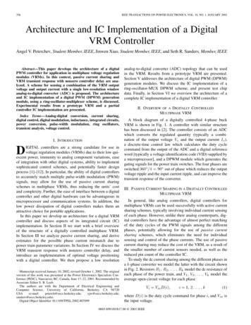
362IEEE TRANSACTIONS ON POWER ELECTRONICS, VOL. 18, NO. 1, JANUARY 2003Fig. 11. Differential output of one ring oscillator delay stage. The upperwaveform is taken from one tap on one stage of the ring, and the lowerwaveform is taken from the symmetric tap from the same stage. The verticalscale is 500 mV/div, and horizontal scale is 200 ns/div.Fig. 10.process.Die photo of ring-oscillator-MUX test chip in 0.25 mCMOSa high control resolution based on a reasonable switchingfrequency. Even worse, in a multiphase application, PWMgeneration circuitry cannot easily be shared among phases, soan independent counter-comparator pair must be implementedfor each phase, leading to increased die area and power.A tapped delay line scheme is proposed in [7]. Power is significantly reduced with respect to the fast-counter-comparatorscheme since the fast clock is replaced by a delay line whichruns at the switching frequency of the converter. One drawbackof this design is that the delay line is not well suited for multiphase application. In a multiphase controller, precise delaymatching among the phases places a stringent symmetry requirement on the delay line. Also, area is a limiting factor forthis scheme since the size of the MUX grows exponentially withthe number of resolution bits .A combined delay line-counter structure is reported in [6],aiming to make a compromise between area and power. However, the asymmetry of the delay line remains a problem for multiphase applications.B. Ring-Oscillator-MUX SchemeA ring-oscillator-MUX implementation of a DPWM module,as illustrated in Fig. 8, has area and power considerations similarto those of the delay line approach. However, this scheme hasthe advantage of a symmetric structure.Main components of the ring-MUX scheme are a 128-stagedifferential ring oscillator, which yields 256 symmetrically oriented taps, and a 256-to-4 MUX that can select appropriate signals from the ring. MUX allows control of PWM timing for eachof four phases, as would be used in a four-phase VRM.A square wave propagates along the ring. When the risingedge reaches tap zero in the ring, the rising edge of the PWMFig. 12. 8-b resolution is achieved between two adjacent outputs of a ringoscillator delay cell. At 1 MHz oscillation frequency, the resolution is 4 ns.signal for phase one is generated. The falling edge of this PWMsignal is generated when the rising edge of the propagatingsquare wave reaches a specified tap in the ring. MUX is usedto specify the tap for phase one, in accord with the commandedduty cycle. The PWM signals for each of phases two throughfour are generated in an analogous manner, but using taps onthe ring offset by 64 positions for each subsequent phase.A fully differential inverter is used as the basic cell of thering oscillator, as shown in Fig. 9, allowing a ring with an evennumber of stages to support a stable oscillation. This makes thering oscillator scheme especially suited for multiphase PWMgeneration since the different phases can be tapped out fromsymmetric positions on the ring.The ring oscillator provides the clock for the digital controller. The frequency of the ring oscillator can be controlled
PETERCHEV et al.: ARCHITECTURE AND IC IMPLEMENTATION OF A DIGITAL VRM CONTROLLER363by adjusting the supply current to the entire ring. The ring frequency obeys the relationship(23)is the current supplied to ring oscillator,iswherevoltage swing seen in the ring, and is a constant. It is straightforward to control frequency by adjusting oscillator current.In principle, a ring oscillator can support more than one frequency mode, depending upon initial condition. Only the quasisquare wave at the fundamental frequency is desirable. Asshown in [4], the dynamics are such that only the fundamentalmode is stable. This result is shown experimentally as well.C. Experimental ResultsA test chip to generate an 8-b resolution PWM signal has beenfabricated on a 0.25 m CMOS process, the die photo of whichis shown in Fig. 10. Instead of using a flat MUX, a binary-treeMUX is used because of its smaller transistor count and smallerarea. The oscillator runs in current-starved mode and the voltageswing is reduced to the range of 0.4 V to 1 V depending on thefrequency. The target dc–dc buck converter applications requireswitching in the frequency range of 100 kHz to 5 MHz. Thecorresponding current drawn by the entire chip comprising thering oscillator and one MUX is 80 A at 5 MHz and less than 1A at 100 kHz. The waveforms of the complementary outputsof one of the stages for operation at 1 MHz are shown in Fig. 11.Fig. 12 shows the LSB resolution of 4 ns for 1 MHz operation.Level converters convert the reduced voltage swing back to railto rail, and each level converter takes 2 A at 1 MHz. In thetest chip, only the fundamental oscillation mode has ever beenobserved.Fig. 13.Block diagram and timing of proposed digital controller IC.VII. CONCLUSIONThis paper developed the architecture of a digital PWMcontroller for application in multiphase VRMs. Passive currentsharing was investigated, and estimates of the phase currentmismatch due to power train parameter variations were derived. The VRM transient response was analyzed, consideringnonzero controller delay, and a scheme for sensing a combination of the VRM output voltage and output current with a singlelow-resolution window ADC was proposed. The architectureand IC implementation of a DPWM generation module, usinga ring-oscillator-MUX scheme, was discussed. Experimentalresults from a prototype VRM and an IC implementation of theDPWM module were presented.APPENDIXCRITICAL INDUCTANCE DERIVATIONFor the converter of Fig. 1, an output voltagetransient rewas discussedsulting from a change of the load current byin Section IV-A and Fig. 4. If the load current step occurs at, then, assuming saturated controller response, thetimeresulting output voltage change follows:(24)VI. DIGITAL CONTROLLER IC ARCHITECTUREA summarizing block diagram of a digital controller IC for afour-phase VRM and the associated timing diagram are shown(seein Fig. 13. The window ADC samplesSection IV-B) at the switching frequency, producing the error.3 The duty cycle calculation block implements a PIDsignalcontrol law (21) using twos complement arithmetic to calcubased on. Digital dither islate the duty cycle commandin orderused to modulate the least significant bits (LSBs) ofto achieve high DPWM resolution with a DPWM module withmoderate hardware resolution [5]. Subsequently, two MUXs areused in an interleaved manner, in conjunction with a differentialring oscillator, to generate the PWM turning-off signals for thefour phases (PWM1OFF, , PWM4OFF). During every switchingis applied to oneperiod, the new duty cycle commandof the MUXs while the other one is holding the previous valueto ensure correct PWM signal generation for allphases. In general, two MUXs are sufficient for updatingin a multiphase application.Test ICs, implementing the duty cycle calculation module andthe DPWM module, were successfully fabricated and tested.3In VRM applications requiring controller delay of less than one switchingperiod, tha ADC can be sampled at a frequency higher than the switching frequency [21].for, and(25). Ifthe magnitude ofreaches aforand then starts decreasing, while ifmaximum atit continues to increase for a while after. Thuscorresponds to the value of for which the first derivative,of (25) is zero at(26)hence(27)is approxiSince the capacitor time constantmately constant for a particular capacitor technology (e.g.
VRM Controller Angel V. Peterchev, Student Member, IEEE, Jinwen Xiao, Student Member, IEEE, and Seth R. Sanders, Member, IEEE Abstract— This paper develops the architecture of a digital PWM controller for application in multiphase voltage regulation modules (VRMs). In this context, passive current sharing and