Transcription
HP ProLiant BL460c Gen9 Server BladeUser GuideAbstractThis document is for the person who installs, administers, and troubleshoots servers and storage systems. HP assumes you are qualified in theservicing of computer equipment and trained in recognizing hazards in products with hazardous energy levels.Part Number: 768826-001September 2014Edition: 1
Copyright 2014 Hewlett-Packard Development Company, L.P.The information contained herein is subject to change without notice. The only warranties for HP products and services are set forth in the expresswarranty statements accompanying such products and services. Nothing herein should be construed as constituting an additional warranty. HP shallnot be liable for technical or editorial errors or omissions contained herein.Microsoft and Windows are U.S. registered trademarks of Microsoft Corporation.
ContentsComponent identification . 6Front panel components . 6Front panel LEDs and buttons . 6Power fault LEDs. 7Drive numbering . 7Hot-plug drive LED definitions . 8System board components . 9System maintenance switch . 9Mezzanine connector definitions . 10DIMM slot locations . 10SUV cable connectors . 11Operations. 12Power up the server blade . 12Power down the server blade . 12Remove the server blade . 13Remove the access panel . 14Remove the DIMM baffle. 14Remove the storage controller . 15Remove the front panel/hard drive cage assembly . 16Remove the mezzanine assembly . 17Remove the FlexibleLOM . 18Install the storage controller . 18Install the access panel . 19Setup. 20Overview . 20Installing an HP BladeSystem c-Class enclosure . 20Preparing the enclosure . 20Installing server blade options . 20Installing interconnect modules . 21Interconnect bay numbering and device mapping. 21Connecting to the network. 22Installing a server blade . 23Completing the configuration. 24Hardware options installation. 25Introduction . 25Drive option. 25Storage controller option . 26HP Smart Storage Battery option . 27Mezzanine card option . 29Memory options . 31HP SmartMemory . 32Memory subsystem architecture . 32Single-, dual-, and quad-rank DIMMs . 33DIMM identification . 33Contents3
Memory configurations . 34General DIMM slot population guidelines . 35Installing a DIMM. 36Processor option. 37HP Trusted Platform Module option . 42Installing the Trusted Platform Module board . 43Retaining the recovery key/password. 45Enabling the Trusted Platform Module . 45Cabling . 46Cabling resources . 46HP Smart Storage Battery cabling . 46Installing the direct connect SATA cable . 47Using the HP c-Class Blade SUV Cable . 47Connecting locally to a server blade with video and USB devices . 47Accessing a server blade with local KVM . 47Accessing local media devices . 48Troubleshooting . 50Troubleshooting resources . 50Software and configuration utilities . 51Server mode . 51Product QuickSpecs. 51HP iLO . 51Active Health System . 52HP RESTful API support for HP iLO . 53Integrated Management Log . 53HP Insight Remote Support . 54Intelligent Provisioning . 55HP Insight Diagnostics . 55Erase Utility . 55Scripting Toolkit for Windows and Linux . 56HP Service Pack for ProLiant . 56HP Smart Update Manager . 56HP UEFI System Utilities. 57Using HP UEFI System Utilities . 57Flexible boot control . 58Restoring and customizing configuration settings . 58Secure Boot configuration . 58Embedded UEFI shell . 59Embedded UEFI diagnostics . 59HP RESTful API support for UEFI . 59Re-entering the server serial number and product ID . 59Utilities and features . 60HP Smart Storage Administrator. 60ROMPaq utility. 60Automatic Server Recovery . 60USB support . 61Redundant ROM support . 61Keeping the system current . 61Drivers . 61Software and firmware . 62Version control . 62Contents4
HP operating systems and virtualization software support for ProLiant servers . 62HP Technology Service Portfolio . 63Change control and proactive notification . 63Battery replacement . 64Regulatory information . 65Safety and regulatory compliance . 65Belarus Kazakhstan Russia marking. 65Turkey RoHS material content declaration . 66Ukraine RoHS material content declaration . 66Warranty information . 66Electrostatic discharge . 67Preventing electrostatic discharge . 67Grounding methods to prevent electrostatic discharge . 67Specifications . 68Environmental specifications . 68Server blade specifications . 68Support and other resources . 69Before you contact HP . 69HP contact information . 69Customer Self Repair . 69Acronyms and abbreviations . 77Documentation feedback . 79Index . 80Contents5
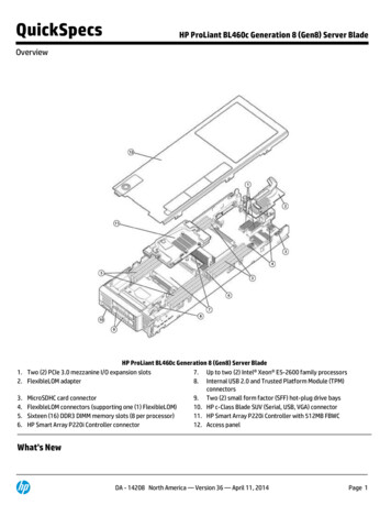
Component identificationFront panel componentsItemDescription1Hard drive bay 12Server blade release button3Server blade release lever4Hard drive bay 25HP c-Class Blade SUV connector* (behind the serial label pulltab)6Serial label pull tab*The SUV connector and the HP c-Class Blade SUV Cable are used for some server blade configuration and diagnosticprocedures.Front panel LEDs and buttonsItem DescriptionStatus1Health status LEDbar*Solid Green Normal (System is powered on)Flashing Green Power On/Standby button service is being initializedFlashing Amber Degraded conditionFlashing Red Critical conditionOff Normal (System is in standby)2Power On/Standby Solid green System onComponent identification6
Item Description3Statusbutton and systempower LED*Flashing green (1 Hz/cycle per sec) Performing power on sequenceSolid amber System in standbyOff No power present**UID button/LED*Solid blue ActivatedFlashing blue: 1 Hz/cycle per sec Remote management or firmware upgrade in progress4 Hz/cycle per sec iLO manual reboot sequence initiated8 Hz/cycle per sec iLO manual reboot sequence in progressOff Deactivated4NIC activity LED*Solid green Link to networkFlashing green (1 Hz/cycle per sec) Network activeOff No network activity*When all four LEDs described in this table flash simultaneously, a power fault has occurred. For more information, see"Power fault LEDs (on page 7)."**Facility power is not present, power cord is not attached, no power supplies are installed, power supply failure hasoccurred, or the power button cable is disconnected.Power fault LEDsThe following table provides a list of power fault LEDs, and the subsystems that are affected. Not all powerfaults are used by all servers.SubsystemLED behaviorSystem board1 flashProcessor2 flashesMemory3 flashesRiser board PCIe slots4 flashesFlexibleLOM5 flashesRemovable HP Flexible Smart Arraycontroller/Smart SAS HBA controller6 flashesSystem board PCIe slots7 flashesPower backplane or storage backplane8 flashesPower supply9 flashesDrive numberingItemDescription1Drive bay 1Component identification7
ItemDescription2Drive bay 2Hot-plug drive LED definitionsItemLEDStatusDefinition1LocateSolid blueThe drive is being identified by a host application.Flashing blueThe drive carrier firmware is being updated or requires an update.Rotating greenDrive activityOffNo drive activitySolid whiteDo not remove the drive. Removing the drive causes one or more ofthe logical drives to fail.OffRemoving the drive does not cause a logical drive to fail.Solid greenThe drive is a member of one or more logical drives.Flashing greenThe drive is rebuilding or performing a RAID migration, strip sizemigration, capacity expansion, or logical drive extension, or iserasing.Flashingamber/greenThe drive is a member of one or more logical drives and predictsthe drive will fail.Flashing amberThe drive is not configured and predicts the drive will fail.Solid amberThe drive has failed.OffThe drive is not configured by a RAID controller.234Activity ringDo not removeDrive statusComponent identification8
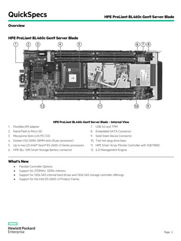
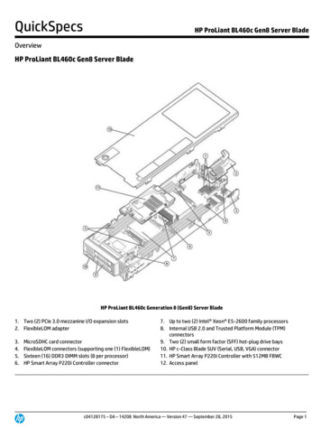
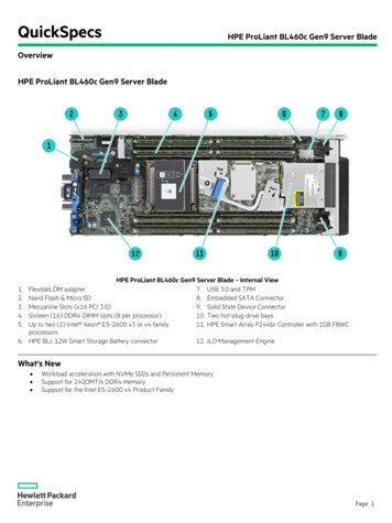
System board componentsItemDescription1System battery2Solid state device connector3Processor 2 DIMM slots (8)4Processor 1 DIMM slots (8)5SAS controller connector6Mezzanine connector 1 (Type A mezzanine only)7Mezzanine connector 2 (Type A or Type B mezzanine)8Enclosure connector9MicroSD card slot10FlexibleLOM connectors (2)11Drive backplane12Internal USB connector13HP Smart Storage Battery connector14Direct-connect SATA connector15System maintenance switch16TPM connectorThe symbolscorrespond to the symbols located on the interconnect bays. For more information, see theHP ProLiant BL460c Gen9 Server Blade Installation Instructions on the HP website (http://www.hp.com/support).System maintenance switchPositionDefaultFunctionS1OffOff iLO security is enabled.On iLO security is disabled.S2OffOff System configuration can bechanged.On System configuration is locked.Component identification9
5OffOff Power-on password is enabled.On Power-on password is disabled.S6OffOff No function.On ROM reads system configurationas invalid.S7OffOff Set default boot mode to UEFI.On Set default boot mode to —ReservedS12—ReservedTo access the redundant ROM, set S1, S5, and S6 to on.When the system maintenance switch position 6 is set to the On position, the system is prepared to erase allsystem configuration settings from both CMOS and NVRAM.CAUTION: Clearing CMOS and/or NVRAM deletes configuration information. Be sure toproperly configure the server or data loss could occur.Mezzanine connector definitionsItemPCIeMezzanine connector 1x16, Type A mezzanine card onlyMezzanine connector 2*x16, Type A or B mezzanine card*When installing a mezzanine option on mezzanine connector 2, processor 2 must be installed.DIMM slot locationsDIMM slots are numbered sequentially (1 through 8) for each processor. The supported AMP modes use thealpha assignments for population order, and the slot numbers designate the DIMM slot ID for sparereplacement.The arrow points to the front of the server blade.Component identification10
SUV cable connectorsCAUTION: Before disconnecting the SUV cable from the connector, always squeeze the releasebuttons on the sides of the connector. Failure to do so can result in damage to the equipment.ItemConnectorDescription1SerialFor trained personnel to connect a null modem serial cableand perform advanced diagnostic procedures2USBFor connecting up to two USB devices3VideoFor connecting a video monitorComponent identification11
OperationsPower up the server bladeThe Onboard Administrator initiates an automatic power-up sequence when the server blade is installed. Ifthe default setting is changed, use one of the following methods to power up the server blade: Use a virtual power button selection through HP iLO. Press and release the Power On/Standby button.When the server blade goes from the standby mode to the full power mode, the system power LED changesfrom amber to solid green. The health status LED bar flashes green when the Power On/Standby Buttonservice is being initialized. For more information about the system power LED status, see "Front panel LEDsand buttons (on page 6)."For more information about the Onboard Administrator, see the enclosure setup and installation guide on theHP website (http://www.hp.com/support/oa).For more information about HP iLO, see "HP iLO (on page 51)."Power down the server bladeBefore powering down the server blade for any upgrade or maintenance procedures, perform a backup ofcritical server data and programs.IMPORTANT: When the server blade is in standby mode, auxiliary power is still being providedto the system.Depending on the Onboard Administrator configuration, use one of the following methods to power downthe server blade: Press and release the Power On/Standby button.This method initiates a controlled shutdown of applications and the OS before the server blade entersstandby mode. Press and hold the Power On/Standby button for more than 4 seconds to force the server blade to enterstandby mode.This method forces the server blade to enter standby mode without properly exiting applications and theOS. If an application stops responding, you can use this method to force a shutdown. Use a virtual power button selection through HP iLO.This method initiates a controlled remote shutdown of applications and the OS before the server bladeenters standby mode. Use the Onboard Administrator CLI to execute one of the following commands:opoweroff server [bay number]This command initiates a controlled shutdown of applications and the OS before the server bladeenters standby mode.Operations12
opoweroff server [bay number] forceThis form of the command forces the server blade to enter standby mode without properly exitingapplications and the OS. If an application stops responding, this method forces a shutdown. Use the Onboard Administrator GUI to initiate a shutdown:a. Select the Enclosure Information tab.b. In the Device Bays item, select the Overall checkbox.c.From the Virtual Power menu, initiate a shutdown of applications and the OS:— For a controlled shutdown, select Momentary Press.— For an emergency shutdown, select Press and Hold.Before proceeding, verify the server blade is in standby mode by observing that the system power LED isamber.Remove the server blade1.Identify the proper server blade.2.Power down the server blade (on page 12).3.Remove the server blade.4.Place the server blade on a flat, level work surface.WARNING: To reduce the risk of personal injury from hot surfaces, allow the drives and theinternal system components to cool before touching them.CAUTION: To prevent damage to electrical components, properly ground the server bladebefore beginning any installation procedure. Improper grounding can cause ESD.Operations13
Remove the access panelTo remove the component:1.Power down the server blade (on page 12).2.Remove the server blade (on page 13).3.Place the server blade on a flat, level work surface.4.Press the access panel release button.5.Slide the access panel towards the rear of the server blade, and then lift to remove the panel.Remove the DIMM baffle1.Power down the server blade (on page 12).2.Remove the server blade (on page 13).3.Place the server blade on a flat, level work surface.4.Remove the access panel (on page 14).5.Disconnect the direct connect SATA cable, if installed ("Installing the direct connect SATA cable" onpage 47).6.Remove the internal USB drive, if installed. To locate the internal USB connector, see "System boardcomponents (on page 9)."IMPORTANT: When removing the right DIMM baffle, leave the HP Smart Storage Batteryinstalled on the baffle. Use the blue pull tab to disconnect the HP Smart Storage Battery cable fromthe system board.7.Remove one or more DIMM baffles:Operations14
oDIMM baffle (right side)oDIMM baffle (left side)Remove the storage controller1.Power down the server blade (on page 12).2.Remove the server blade (on page 13).Operations15
3.Place the server blade on a flat, level work surface.4.Remove the access panel (on page 14).5.Prepare the storage controller for removal.6.Remove the storage controller.Remove the front panel/hard drive cage assembly1.Power down the server blade (on page 12).2.Remove the server blade (on page 13).3.Place the server blade on a flat, level work surface.4.Remove the access panel (on page 14).5.Disconnect the direct connect SATA cable, if installed ("Installing the direct connect SATA cable" onpage 47).Operations16
6.Remove the internal USB drive, if installed. To locate the internal USB connector, see "System boardcomponents (on page 9)."7.Remove all DIMM baffles ("Remove the DIMM baffle" on page 14).8.Remove the storage controller (on page 15).CAUTION: Always remove the SAS controller before removing the front panel/drive cageassembly.9.Extend the serial label pull tab from the front of the server blade.10.Remove the two T-15 screws from the front panel/drive cage assembly.11.Remove the front panel/drive cage assembly.Remove the mezzanine assembly1.Power down the server blade (on page 12).2.Remove the server blade (on page 13).3.Place the server blade on a flat, level work surface.4.Remove the access panel (on page 14).Operations17
5.Remove the mezzanine assembly.Remove the FlexibleLOM1.Power down the server blade (on page 12).2.Remove the server blade (on page 13).3.Place the server blade on a flat, level work surface.4.Remove the access panel (on page 14).5.Remove the mezzanine assembly (on page 17).6.Use the FlexibleLOM handle to remove the FlexibleLOM from the system board.Install the storage controller1.Power down the server blade (on page 12).Operations18
2.Remove the se
HP ProLiant BL460c Gen9 Server Blade User Guide Abstract This document is for the person who installs, administers, and troubleshoots servers and storage systems.