Transcription
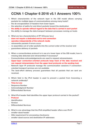
CCNA SecurityChapter 11 - CCNA Security Comprehensive LabThis lab has been updated for use on NETLAB Topology 2018 Cisco and/or its affiliates. All rights reserved. This document is Cisco Public.Page 1 of 18
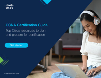
Chapter 11 – Comprehensive LabCCNA SecurityIP Addressing TableDeviceInterfaceIP AddressSubnet MaskDefault GatewaySwitch PortG0/0209.165.200.225255.255.255.248N/AASA G1/1S0/0/0 (DCE)10.1.1.1255.255.255.252N/AN/ALoopback 5.255.252N/AN/AS0/0/1 5.255.255.0N/AS3 F0/5S0/0/110.2.2.1255.255.255.252N/AN/AS1VLAN 1192.168.2.11255.255.255.0192.168.2.1N/AS2VLAN 1192.168.1.11255.255.255.0192.168.1.1N/AS3VLAN 1.1255.255.255.0N/AS2 F0/24G1/1209.165.200.226255.255.255.248N/AR1 G0/0G1/3192.168.2.1255.255.255.0N/AS1 F0/24PC-ANIC192.168.2.3255.255.255.0192.168.2.1S1 F0/6PC-BNIC192.168.1.3255.255.255.0192.168.1.1S2 F0/18PC-CNIC172.16.3.3255.255.255.0172.16.3.1S3 F0/18R1R2R3ASAObjectivesPart 1: Create a Basic Technical Security PolicyPart 2: Configure Basic Device SettingsPart 3: Configure Secure Router Administrative Access Configure encrypted passwords and a login banner. Configure the EXEC timeout value on console and VTY lines. Configure login failure rates and VTY login enhancements. Configure Secure Shell (SSH) access and disable Telnet. Configure local authentication, authorization, and accounting (AAA) user authentication. Secure the router against login attacks, and secure the IOS image and the configuration file. Configure a router NTP server and router NTP clients. Configure router syslog reporting and a syslog server on a local host.Part 4: Configure a Zone-Based Policy Firewall and Intrusion Prevention System Configure a Zone-Based Policy Firewall (ZPF) on an ISR using the CLI. Configure an intrusion prevention system (IPS) on an ISR using the CLI.Part 5: Secure Network Switches Configure passwords and a login banner. 2018 Cisco and/or its affiliates. All rights reserved. This document is Cisco Public.Page 2 of 18
CCNA Security Configure management VLAN access. Secure access ports. Protect against Spanning Tree Protocol (STP) attacks. Configure port security and disable unused ports.Chapter 11 – Comprehensive LabPart 6: Configure ASA Basic Settings and Firewall Configure basic settings, passwords, date, and time. Configure the inside and outside VLAN interfaces. Configure port address translation (PAT) for the inside network. Configure a Dynamic Host Configuration Protocol (DHCP) server for the inside network. Configure administrative access via Telnet and SSH. Configure a static default route for the Adaptive Security Appliance (ASA). Configure Local AAA user authentication. Configure a DMZ with a static NAT and ACL. Verify address translation and firewall functionality.Part 7 Configure a DMZ, Static NAT, and ACLs on an ASAPart 8: Configure ASA Clientless SSL VPN Remote Access Using ASDM Configure a remote access SSL VPN using the Cisco Adaptive Security Device Manager (ASDM). Verify SSL VPN access to the portal.Part 9: Configure a Site-to-Site VPN between the ASA and ISR Configure an IPsec site-to-site VPN between the ASA and R3 using ASDM and the CLI. Activate and verify the IPsec site-to-site VPN tunnel between the ASA and R3.Background/ScenarioThis comprehensive lab is divided into nine parts. The parts should be completed sequentially. In Part 1, youwill create a basic technical security policy. In Part 2, you will configure the basic device settings. In Part 3,you will secure a network router using the command-line interface (CLI) to configure IOS features, includingAAA and SSH. In Part 4, you will configure a ZPF and IPS on an ISR. In Part 5, you will configure a networkswitch using the CLI. In Parts 7 and 8, you will configure the ASA firewall functionality and clientless SSL VPNremote access. In Part 9, you will configure a site-to-site VPN between the ASA and R3.Note: The router commands and output in this lab are from a Cisco 1941 router with Cisco IOS Release15.4(3)M2 (with a Security Technology Package license). The switch commands and output are from CiscoWS-C2960-24TT-L switches with Cisco IOS Release 15.0(2)SE7 (C2960-LANBASEK9-M image). Otherrouters, switches, and Cisco IOS versions can be used. See the Router Interface Summary Table at the endof the lab to determine which interface identifiers to use based on the equipment in the lab. Depending on therouter, or switch model and Cisco IOS version, the commands available and the output produced might varyfrom what is shown in this lab.The ASA used with this lab is a Cisco model 5506 with an 8-port integrated router, running OS version 9.8(1),Adaptive Security Device Manager (ASDM) version 7.8(1), and comes with a Base license. 2018 Cisco and/or its affiliates. All rights reserved. This document is Cisco Public.Page 3 of 18
CCNA SecurityChapter 11 – Comprehensive LabPart 1: Create a Basic Technical Security Policy (Chapters 1 and 11)In Part 1, you will create a Network Device Security Guidelines document that can serve as part of acomprehensive network security policy. This document addresses specific router and switch securitymeasures and describes the security requirements to be implemented on the infrastructure equipment.Task 1: Identify Potential Sections of a Basic Network Security Policy.A network security policy should include several key sections that can address potential issues for users,network access, device access, and other areas. List some key sections you think could be part of a basicsecurity policy.Task 2: Create a “Network Equipment Security Guidelines” document as a supplementto a Basic Security PolicyStep 1: Review the objectives from previous CCNA Security labs.a. Open each of the labs completed from chapters 1 to 9, and review the objectives listed for each one.b. Copy the objectives to a separate document and use it as a starting point. Focus on the objectives thatinvolve security practices and device configuration.Step 2: Create a “Network Device Security Guidelines” document for router and switch security.Create a high-level list of tasks to include for network access and device security. This document shouldreinforce and supplement the information presented in a basic security policy. It is based on the content ofprevious CCNA Security labs and on the networking devices present in the course lab topology.Note: The “Network Device Security Guidelines” document should be no more than two pages, and will be thebasis for the equipment configuration in the remaining parts of the lab.Step 3: Submit the “Network Device Security Guidelines” to your instructor.Provide the “Network Device Security Guidelines” document to your instructor for review before starting Part 2of this lab. You can send the document as an e-mail attachment or put it on removable storage media, suchas a flash drive.Part 2: Configure Basic Device Settings (Chapters 2 and 6)Step 1: Configure basic settings for all routers.a. Configure hostnames, as shown in the topology.b. Configure the interface IP addresses, as shown in the IP addressing table.c.Configure a serial interface DCE clock rate of 128000 for the routers, if using routers other than thosespecified with this lab.d. Disable DNS lookup on each router.Step 2: Configure static default routes on R1 and R3.a. Configure a static default route from R1 to R2 and from R3 to R2. 2018 Cisco and/or its affiliates. All rights reserved. This document is Cisco Public.Page 4 of 18
CCNA SecurityChapter 11 – Comprehensive Labb. Configure static routes from R2 to the R1 simulated LAN (Loopback 1), the R1 Gi0/0-to-ASA subnet, andthe R3 LAN.Step 3: Configure basic settings for each switch.a. Configure hostnames, as shown in the topology.b. Configure the VLAN 1 management address on each switch, as shown in the IP Addressing table.c.Configure the IP default gateway for each of the three switches.d. Disable DNS lookup on each switch.Step 4: Configure PC host IP settings.Configure a static IP address, subnet mask, and default gateway for each PC, as shown in the IP Addressingtable.Step 5: Verify connectivity between PC-C and R1 G0/0.Step 6: Save the basic running configuration for each router and switch.Part 3: Configure Secure Router Administrative Access (Chapters 2 and 3)You will use the CLI to configure passwords and device access restrictions.Task 1: Configure Settings for R1 and R3Step 1: Configure a minimum password length of 10 characters.Step 2: Encrypt plaintext passwords.Step 3: Configure a login warning banner.Configure a warning to unauthorized users with a message-of-the-day (MOTD) banner that says:Unauthorized access strictly prohibited and prosecuted to the full extent of the law!.Step 4: Configure the enable secret password.Use cisco12345 as the enable secret password. Use the strongest encryption type available.Step 5: Configure the local user database.Create a local user account of Admin01 with a secret password of Admin01pa55 and a privilege level of 15.Use the strongest encryption type available.Step 6: Enable AAA services.Step 7: Implement AAA services using the local database.Create the default login authentication method list. Use case-sensitive local authentication as the first optionand the enable password as the backup option to be used if an error occurs in relation to local authentication.Step 8: Configure the console line.Configure the console line for privilege level 15 access on login. Set the exec-timeout value to log out after15 minutes of inactivity. Prevent console messages from interrupting command entry. 2018 Cisco and/or its affiliates. All rights reserved. This document is Cisco Public.Page 5 of 18
CCNA SecurityChapter 11 – Comprehensive LabStep 9: Configure the VTY lines.Configure the VTY lines for privilege level 15 access on login. Set the exec-timeout value to log out asession after 15 minutes of inactivity. Allow for remote access using SSH only.Step 10: Configure the router to log login activity.a. Configure the router to generate system logging messages for successful and failed login attempts.Configure the router to log every successful login. Configure the router to log every second failed loginattempt.b. Issue the show login command. What additional information is displayed?Step 11: Enable HTTP access.a. Enable the HTTP server on R1 to simulate an Internet target for later testing.b. Configure HTTP authentication to use the local user database on R1.Task 2: Configure the SSH Server on R1 and R3Step 1: Configure the domain name.Configure a domain name of ccnasecurity.com.Step 2: Generate the RSA encryption key pair.Configure the RSA keys with 1024 as the number of modulus bits.Step 3: Configure the SSH version.Specify that the router accept only SSH version 2 connections.Step 4: Configure SSH timeouts and authentication parameters.The default SSH timeouts and authentication parameters can be altered to be more restrictive. ConfigureSSH timeout to 90 seconds and the number of authentication attempts to 2.Step 5: Verify SSH connectivity to R1 from PC-C.a. Launch the SSH client on PC-C, enter the R1 S0/0/0 IP address (10.1.1.1), and log in as Admin01 withthe password Admin01pa55. If prompted by the SSH client with a security alert regarding the server’shost key, click Yes.b. Issue the show run command from the SSH session on PC-C. The configuration for R1 should bedisplayed.Task 3: Secure against Login Attacks and Secure the IOS and Configuration File on R1Step 1: Configure enhanced login security.If a user experiences two failed login attempts within a 30-second time span, disable logins for 1 minute. Logall failed login attempts. 2018 Cisco and/or its affiliates. All rights reserved. This document is Cisco Public.Page 6 of 18
CCNA SecurityChapter 11 – Comprehensive LabStep 2: Secure the Cisco IOS image and archive a copy of the running configuration.a. The secure boot-image command enables Cisco IOS image resilience, which hides the file from the dirand show commands. The file cannot be viewed, copied, modified, or removed using EXEC modecommands. (It can be viewed in ROMMON mode.)b. The secure boot-config command takes a snapshot of the router running configuration and securelyarchives it in persistent storage (flash).Step 3: Verify that your image and configuration are secured.a. You can use only the show secure bootset command to display the archived filename. Display thestatus of configuration resilience and the primary bootset filename.What is the name of the archived running config file and on what is the name based?b. Save the running configuration to the startup configuration from the privileged EXEC mode prompt.Step 4: Restore the IOS and configuration files back to the default setting.You have verified the Secure IOS and configuration file settings. Now, use the no secure boot-image and nosecure boot config commands to restore the default settings for these files.Task 4: Configure a Synchronized Time Source Using NTPR2 will be the master NTP clock source for R1 and R3.Step 1: Set up the NTP master using Cisco IOS commands.R2 is the master NTP server in this lab. All other routers and switches learn the time from it, either directly orindirectly. For this reason, you must ensure that R2 has the correct UTC set.a. Use the show clock command to display the current time set on the router.b. Use the clock set time command to set the time on the router.c.Configure NTP authentication by defining the authentication key number 1 with md5 hashing, and apassword of NTPpassword. The password is case sensitive.d. Configure the trusted key that will be used for authentication on R2.e. Enable the NTP authentication feature on R2.f.Configure R2 as the NTP master using the ntp master stratum-number command in global configurationmode. The stratum number indicates the distance from the original source. For this lab, use a stratumnumber of 3 on R2. When a device learns the time from an NTP source, its stratum number becomes onegreater than the stratum number of its source.Step 2: Configure R1 and R3 as NTP clients using the CLI.a. Configure NTP authentication by defining the authentication key number 1 with md5 hashing, and apassword of NTPpassword.b. Configure the trusted key that will be used for authentication. This command provides protection againstaccidentally synchronizing the device with a time source that is not trusted.c.Enable the NTP authentication feature. 2018 Cisco and/or its affiliates. All rights reserved. This document is Cisco Public.Page 7 of 18
CCNA SecurityChapter 11 – Comprehensive Labd. R1 and R3 will become NTP clients of R2. Use the ntp server hostname global configuration modecommand. Use R2’s serial IP address for the hostname. Issue the ntp update-calendar command on R1and R3 to periodically update the calendar with the NTP time.e. Use the show ntp associations command to verify that R1 has made an association with R2. You canalso use the more verbose version of the command by adding the detail argument. It might take sometime for the NTP association to form.f.Verify the time on R1 and R3 after they have made NTP associations with R2.Task 5: Configure Syslog Support on R3 and PC-CStep 1: Install the syslog server on PC-C.a. The Tftpd32 software from jounin.net is free to download and install, and it includes a TFTP server, TFTPclient, and a syslog server and viewer.b. Open Tftpd32, click Settings, and ensure that the syslog server check box is checked. In the SYSLOGtab, you can configure a file for saving syslog messages. Close the settings and in the main Tftpd32interface window, note the server interface IP address and select the Syslog server tab to bring it to theforeground.Step 2: Configure R3 to log messages to the syslog server using the CLI.a. Verify that you have connectivity between R3 and PC-C by pinging the R3 G0/1 interface IP address172.16.3.1 from PC-C. If it is unsuccessful, troubleshoot as necessary before continuing.b. NTP was configured in Task 4 to synchronize the time on the network. Displaying the correct time anddate in syslog messages is vital when using syslog to monitor a network. If the correct time and date of amessage is not known, it can be difficult to determine what network event caused the message.Verify that the timestamp service for logging is enabled on the router by using the show run command.Use the service timestamps log datetime msec command to verify.c.Configure the syslog service on the router to send syslog messages to the syslog server.Step 3: Configure the logging severity level on R3.Logging traps can be set to support the logging function. A trap is a threshold that triggers a log message.The level of logging messages can be adjusted to allow the administrator to determine what kinds ofmessages are sent to the syslog server. Routers support different levels of logging. The eight levels rangefrom 0 (emergencies), which indicates that the system is unstable, to 7 (debugging), which sends messagesthat include router information.Note: The default level for syslog is 6 (informational logging). The default for console and monitor logging is 7(debugging).a. Use the logging trap command to set the severity level for R3 to level 4 (warnings).b. Use the show logging command to see the type and level of logging enabled. 2018 Cisco and/or its affiliates. All rights reserved. This document is Cisco Public.Page 8 of 18
CCNA SecurityChapter 11 – Comprehensive LabPart 4: Configure a Zone-Based Policy Firewall and Intrusion PreventionSystem (Chapters 4 and 5)In Part 4, you will configure a ZPF and IPS on R3 using the CLI.Task 1: Configure a ZPF on R3 using the CLIStep 1: Creating the security zones.a. Create the INSIDE and OUTSIDE security zones.b. Create an inspect class-map to match the traffic to be allowed from the INSIDE zone to the OUTSIDEzone. Because we trust the INSIDE zone, we allow all the main protocols. Use the match-any keyword toinstruct the router that the following match protocol statements will qualify as a successful match. Thisresults in a policy being applied. Match for TCP, UDP, or ICMP packets.c.Create an inspect policy-map named INSIDE-TO-OUTSIDE. Bind the INSIDE-PROTOCOLS class-mapto the policy-map. All packets matched by the INSIDE-PROTOCOLS class-map will be inspected.d. Create a zone-pair called INSIDE-TO-OUTSIDE that allows traffic initiated from the internal network to theexternal network but does not allow traffic originating from the external network to reach the internalnetwork.e. Apply the policy-map to the zone-pair.f.Assign R3’s G0/1 interface to the INSIDE security zone and the S0/0/1 interface to the OUTSIDE securityzone.g. Verify your ZPF configuration by using the show zone-pair security, show policy-map type inspectzone-pair, and show zone security commands.Task 2: Configure IPS on R3 using the CLI.Step 1: Prepare router R3 and the TFTP server.To configure Cisco IOS IPS 5.x, the IOS IPS signature package file and public crypto key files must beavailable on the PC with the TFTP server installed. R3 uses PC-C as the TFTP server. Ask your instructor ifthese files are not on the PC.a. Verify that the IOS-Sxxx-CLI.pkg signature package file is in the default TFTP folder. The xxx is theversion number and varies depending on which file was downloaded from Cisco.com.b. Verify that the realm-cisco.pub.key.txt file is available and note its location on PC-C. This is the publiccrypto key used by Cisco IOS IPS.c.Verify or create the IPS directory (ipsdir) in router flash on R3. From the R3 CLI, display the content offlash memory and check to see if the ipsdir directory exists.d. If the ipsdir directory is not listed, create it in privileged EXEC mode, using the mkdir command.Note: If the IPSDIR directory is listed and there are files in it, contact your instructor. This directory mustbe empty before configuring IPS. If there are no files in it, you may proceed to configure IPS.Step 2: Verify the IOS IPS signature package location and TFTP server setup.a. Use the ping command to verify connectivity between R3, PC-C, and the TFTP server.b. Start Tftpd32 (or another TFTP server) and set the default directory to the one with the IPS signaturepackage in it. Note the filename for use in the next step. 2018 Cisco and/or its affiliates. All rights reserved. This document is Cisco Public.Page 9 of 18
Chapter 11 – Comprehensive LabCCNA SecurityStep 3: Copy and paste the crypto key file into R3’s configuration.In global configuration mode, select and copy the crypto key file named realm-cisco.pub.key.txt. Pastethe copied crypto key content at the global configuration mode prompt.Note: The contents of the realm-cisco.pub.key.txt file have been provided below:crypto key pubkey-chain rsanamed-key realm-cisco.pub signaturekey-string30820122 300D0609 2A864886 F70D010100C19E93 A8AF124A D6CC7A24 5097A97517E630D5 C02AC252 912BE27F 37FDD9C8B199ABCB D34ED0F9 085FADC1 359C189E5B2146A9 D7A5EDE3 0298AF03 DED7A5B8FE3F0C87 89BCB7BB 994AE74C FA9E481D50437722 FFBE85B9 5E4189FF CC189CB9006CF498 079F88F8 A3B3FB1F 9FB7B3CB2F56D826 8918EF3C 80CA4F4D 87BFCA3BF3020301 53053EC0112A35F0B08B85AD768C36892356AEB4B094D3Step 4: Configure the IPS settings on R3 from the CLI.a. Create an IPS rule, and name the rule IOSIPS.b. Set the IPS Signature storage location to the IPSDIR directory you created in flash in step 1d.c.Enable HTTP server and IPS SDEE event notification.d. Configure IOS IPS to use one of the pre-defined signature categories.Note: When configuring IOS IPS, it is required to first retire all the signatures in the “all” category and thenunretire selected signature categories.After you have retired all signatures in the all category, unretire the ios ips basic category.e. Apply the IPS rule to inbound traffic to R3’s S0/0/1 interface.Step 5: Start the TFTP server on PC-C and verify the IPS file directory.Verify that PC-C has the IPS Signature package file in a directory on the TFTP server. This file is typicallynamed IOS-Sxxx-CLI.pkg. The xxx is the signature file version.Note: If this file is not present, contact your instructor before continuing.Step 6: Copy the signature package from the TFTP server to R3.a. Use the copy tftp command to retrieve the signature file and load it into the Intrusion DetectionConfiguration. Use the idconf keyword at the end of the copy command.Note: Signature compiling begins immediately after the signature package is loaded to the router. Youcan see the messages on the router with logging level 6 or above enabled.b. Use the dir flash command to see the contents of the IPSDIR directory you created earlier in this lab.There should be six files, as shown here.Note: You may see an error message during signature compilation, such as “%IPS-3INVALID DIGITAL SIGNATURE: Invalid Digital Signature found (key not found)”. The message means 2018 Cisco and/or its affiliates. All rights reserved. This document is Cisco Public.Page 10 of 18
CCNA SecurityChapter 11 – Comprehensive Labthe public crypto key is invalid. Refer to Task 3, Configure the IPS Crypto Key, to reconfigure the publiccrypto key.c.Use the show ip ips all command to view the IPS configuration status summary.Part 5: Secure Network Switches (Chapter 6)Note: Not all security features in this part of the lab will be configured on all switches. However, in aproduction network all security features would be configured on all switches.Step 1: Configure basic security settings on S1a. HTTP access to the switch is enabled by default. Prevent HTTP access by disabling the HTTP server andHTTP secure server.Use an enable secret password of cisco12345. Use the strongest encryption available.b. Encrypt plaintext passwords.c.Configure a warning to unauthorized users with an MOTD banner that says “Unauthorized accessstrictly prohibited!”.Step 2: Configure SSH server settings on S1.a. Configure a domain name.b. Configure username Admin01 in the local database with a password of Admin01pa55. Configure thisuser to have the highest possible privilege level. The strongest encryption method available should beused for the password.c.Configure the RSA keys with 1024 modulus bits.d. Enable SSH version 2.e. Set the SSH time-out to 90 seconds and the number of authentication retries to 2.Step 3: Configure the console and VTY lines.a. Configure a console to use the local database for login. If the user has the highest privileges, thenautomatically enable privilege exec mode upon login. Set the exec-timeout value to log out after fiveminutes of inactivity. Prevent console messages from interrupting command entry.b. Configure VTY lines to use the local database for login. If the user has the highest privileges, thenautomatically enable privilege exec mode upon login. Set the exec-timeout value to log out after fiveminutes of inactivity. Allow remote SSH access to all VTY linesStep 4: Configure Port Security and Disable Unused Portsa. Disable trunking on port F0/7.b. Enable PortFast on F0/7.c.Enable BPDU guard on F0/7.d. Apply basic default port security on F0/7. This sets the maximum MAC addresses to 1 and the violationaction to shut down. Use the sticky option to allow the secure MAC address that is dynamically learnedon a port to the switch running configuration.e. Disable unused ports on S1. 2018 Cisco and/or its affiliates. All rights reserved. This document is Cisco Public.Page 11 of 18
CCNA SecurityChapter 11 – Comprehensive LabStep 5: Set loop guard as the default for all non-designated ports on S1.Step 6: Save the running configuration to the startup configuration for each switch.Part 6: Configure ASA Basic Settings and Firewall (Chapter 9)Task 1: Prepare the ASA for ASDM AccessStep 1: Clear the previous ASA configuration settings.a. Use the write erase command to remove the startup-config file from flash memory.b. Use the reload command to restart the ASA.Step 2: Bypass Setup Mode and configure the ASDM VLAN interfaces using the CLI.a. When prompted to preconfigure the firewall through interactive prompts (Setup mode), respond with no.b. Enter privileged EXEC mode. The password should be blank (no password) at this point.c.Enter global configuration mode. Respond with no to the prompt to enable anonymous reporting.The Gi1/2 interface will be used by PC-B to access ASDM on the ASAConfigure interface Gi1/2 and name it inside. The Security Level should be automatically set to thehighest level of 100. Specify IP address 192.168.1.1 and subnet mask 255.255.255.0.d. Preconfigure interface Gi1/1, name it outside, assign IP address 209.165.200.226, and the subnet mask255.255.255.248. Notice that the interface is automatically assigned a 0 as the security level.e. Configure interface Gi1/3, which is where the public access web server will reside. Assign it IP address192.168.2.1/24, name it dmz, and assign it a security level of 70.f.Display the status of all ASA interfaces by using the show interface ip brief command.g.Display the information for the Layer 3 interfaces by using the show ip address command.Step 3: Configure and verify access to the ASA from the inside network.a. From PC-B, ping the ASA’s inside interface (192.168.1.1). Pings should be successful.b. Use the http command to configure the ASA to accept HTTPS connections and to allow access to ASDMfrom any host on the inside network (192.168.1.0/24).c.Open a browser on PC-B and test the HTTPS access to the ASA by entering https://192.168.1.1.d. From the ASDM Welcome page, click Run ASDM. When prompted for a username and password, leavethem blank and click OK. Click Cancel on the FirePower module window.Task 2: Configure Basic ASA Settings Using the ASDM Startup WizardStep 1: Access the Configuration menu and launch the Startup wizard.At the top left of the screen, click Configuration Launch Startup wizard.Step 2: Configure the hostname, domain name, and the enable password.a. On the first Startup wizard screen, select the Modify Existing Configuration option.b. On the Startup Wizard Step 2 screen, configure the ASA hostname CCNAS-ASA and domain nameccnasecurity.com. Change the enable mode password from blank (no password) to cisco12345. 2018 Cisco and/or its affiliates. All rights reserved. This document is Cisco Public.Page 12 of 18
CCNA SecurityChapter 11 – Comprehensive LabStep 3: Verify the interface settings.a.On the Startup Wizard Step 3 and 4 screens, verify the Outside and Inside IP address settings arecorrect. Click Next.b.On the Startup Wizard Step 5 screen, do not change the Static Routes settings. Click Next.Step 4: Configure DHCP, address translation, and administrative access.a.On the Startup Wizard Step 6 screen – DHCP Server, select Enable DHCP server on the InsideInterface and specify a starting IP address of 192.168.1.5 and an ending IP address of 192.168.1.30.Enter the DNS Server 1 address of 10.3.3.3 and enter ccnasecurity.com for the domain name.Do NOT check the box to enable auto-configuration from interface.b.On the Startup Wizard Step 7 screen – Address Translation (NAT/PAT), configure the ASA to Use PortAddress Translation (PAT) and select the Use the IP address on the outside interface option.c.On the Startup Wizard Step 8 screen – Administrative Access, HTTPS/ASDM access is currentlyconfigured for hosts on the inside network (192.168.1.0/24). Add SSH access to the ASA for the insidenetwork (192.168.1.0) with a subnet mask of 255.255.255.0.d.Select Finish to close the wizard and deliver the commands to the ASA.Note: When prompted to log in again, leave the Username field blank and enter cisco12345 as thepassword.Task 3: Configurin
Step 1: Review the objectives from previous CCNA Security labs. a. Open each of the labs completed from chapters 1 to 9, and review the objectives listed for each one. b. Copy the objectives to a separate document and use it as a starting point. Focus on the objectives that involve security practices and device configuration.