Transcription
Chapter 14Interference and Diffraction14.1 Superposition of Waves . 14-214.2 Young’s Double-Slit Experiment . 14-4Example 14.1: Double-Slit Experiment. 14-714.3 Intensity Distribution . 14-8Example 14.2: Intensity of Three-Slit Interference . 14-1114.4 Diffraction. 14-1314.5 Single-Slit Diffraction. 14-13Example 14.3: Single-Slit Diffraction . 14-1514.6 Intensity of Single-Slit Diffraction . 14-1614.7 Intensity of Double-Slit Diffraction Patterns. 14-1914.8 Diffraction Grating . 14-2014.9 Summary. 14-2214.10 Appendix: Computing the Total Electric Field. 14-2314.11 Solved Problems . ble-Slit Experiment . 14-26Phase Difference . 14-27Constructive Interference. 14-28Intensity in Double-Slit Interference . 14-29Second-Order Bright Fringe . 14-30Intensity in Double-Slit Diffraction . 14-3014.12 Conceptual Questions . 14-3314.13 Additional Problems . ble-Slit Interference. 14-33Interference-Diffraction Pattern. 14-33Three-Slit Interference . 14-34Intensity of Double-Slit Interference . 14-34Secondary Maxima . 14-34Interference-Diffraction Pattern. 14-3514-1
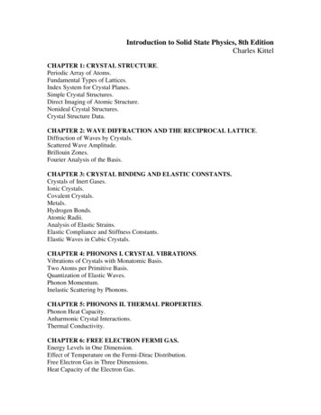
Interference and Diffraction14.1Superposition of WavesConsider a region in space where two or more waves pass through at the same time.According to the superposition principle, the net displacement is simply given by thevector or the algebraic sum of the individual displacements. Interference is thecombination of two or more waves to form a composite wave, based on such principle.The idea of the superposition principle is illustrated in Figure 14.1.1.(a)(b)(c)(d)Figure 14.1.1 Superposition of waves. (b) Constructive interference, and (c) destructiveinterference.Suppose we are given two waves,ψ 1 ( x, t ) ψ 10 sin( k1 x ω1t φ1 ),ψ 2 ( x, t ) ψ 20 sin(k2 x ω2t φ2 )(14.1.1)the resulting wave is simplyψ ( x, t ) ψ 10 sin(k1 x ω1t φ1 ) ψ 20 sin(k2 x ω2t φ2 )(14.1.2)The interference is constructive if the amplitude of ψ ( x, t ) is greater than the individualones (Figure 14.1.1b), and destructive if smaller (Figure 14.1.1c).As an example, consider the superposition of the following two waves at t 0 :ψ 1 ( x) sin x, ψ 2 ( x) 2sin x π 4 (14.1.3)The resultant wave is given by14-2
ψ ( x) ψ 1 ( x) ψ 2 ( x) sin x 2sin x π () 1 2 sin x 2 cos x4 (14.1.4)where we have usedsin(α β ) sin α cos β cos α sin β(14.1.5)and sin(π / 4) cos(π / 4) 2 / 2 . Further use of the identity aba sin x b cos x a 2 b 2 sin x cos x 22a 2 b2 a b a 2 b 2 [ cos φ sin x sin φ cos x ](14.1.6) a 2 b 2 sin( x φ )with b φ tan 1 a(14.1.7)ψ ( x) 5 2 2 sin( x φ )(14.1.8)then leads towhere φ tan 1 ( 2 /(1 2)) 30.4 0.53 rad. The superposition of the waves isdepicted in Figure 14.1.2.Figure 14.1.2 Superposition of two sinusoidal waves.We see that the wave has a maximum amplitude when sin( x φ ) 1 , or x π / 2 φ .The interference there is constructive. On the other hand, destructive interference occursat x π φ 2.61 rad , where sin(π ) 0 .14-3
In order to form an interference pattern, the incident light must satisfy two conditions:(i) The light sources must be coherent. This means that the plane waves from the sourcesmust maintain a constant phase relation. For example, if two waves are completely out ofphase with φ π , this phase difference must not change with time.(ii) The light must be monochromatic. This means that the light consists of just onewavelength λ 2π / k .Light emitted from an incandescent lightbulb is incoherent because the light consists owaves of different wavelengths and they do not maintain a constant phase relationship.Thus, no interference pattern is observed.Figure 14.1.3 Incoherent light source14.2Young’s Double-Slit ExperimentIn 1801 Thomas Young carried out an experiment in which the wave nature of light wasdemonstrated. The schematic diagram of the double-slit experiment is shown in Figure14.2.1.Figure 14.2.1 Young’s double-slit experiment.A monochromatic light source is incident on the first screen which contains a slit S0 . Theemerging light then arrives at the second screen which has two parallel slits S1 and S2.which serve as the sources of coherent light. The light waves emerging from the two slitsthen interfere and form an interference pattern on the viewing screen. The bright bands(fringes) correspond to interference maxima, and the dark band interference minima.14-4
Figure 14.2.2 shows the ways in which the waves could combine to interfereconstructively or destructively.Figure 14.2.2 Constructive interference (a) at P, and (b) at P1. (c) Destructiveinterference at P2.The geometry of the double-slit interference is shown in the Figure 14.2.3.Figure 14.2.3 Double-slit experimentConsider light that falls on the screen at a point P a distance y from the point O thatlies on the screen a perpendicular distance L from the double-slit system. The two slitsare separated by a distance d. The light from slit 2 will travel an extra distance δ r2 r1to the point P than the light from slit 1. This extra distance is called the path difference.From Figure 14.2.3, we have, using the law of cosines,22 d π d r12 r 2 dr cos θ r 2 dr sin θ 2 2 2 (14.2.1)and22 d π d r2 2 r 2 dr cos θ r 2 dr sin θ 2 2 2 (14.2.2)Subtracting Eq. (142.1) from Eq. (14.2.2) yields14-5
r2 2 r12 (r2 r1 )(r2 r1 ) 2dr sin θ(14.2.3)In the limit L d , i.e., the distance to the screen is much greater than the distancebetween the slits, the sum of r1 and r2 may be approximated by r1 r2 2r , and the pathdifference becomesδ r2 r1 d sin θ(14.2.4)In this limit, the two rays r1 and r2 are essentially treated as being parallel (see Figure14.2.4).Figure 14.2.4 Path difference between the two rays, assuming Ld.Whether the two waves are in phase or out of phase is determined by the value of δ .Constructive interference occurs when δ is zero or an integer multiple of the wavelengthλ:δ d sin θ mλ , m 0, 1, 2, 3, . (constructive interference)(14.2.5)where m is called the order number. The zeroth-order (m 0) maximum corresponds tothe central bright fringe at θ 0 , and the first-order maxima ( m 1 ) are the brightfringes on either side of the central fringe.On the other hand, when δ is equal to an odd integer multiple of λ / 2 , the waves will be180 out of phase at P, resulting in destructive interference with a dark fringe on thescreen. The condition for destructive interference is given by 1 δ d sin θ m λ , m 0, 1, 2, 3, . (destructive interference)2 (14.2.6)In Figure 14.2.5, we show how a path difference of δ λ / 2 ( m 0 ) results in adestructive interference and δ λ ( m 1 ) leads to a constructive interference.14-6
Figure 14.2.5 (a) Destructive interference. (b) Constructive interference.To locate the positions of the fringes as measured vertically from the central point O, inaddition to L d , we shall also assume that the distance between the slits is muchgreater than the wavelength of the monochromatic light, d λ . The conditions implythat the angle θ is very small, so thatsin θ tan θ yL(14.2.7)Substituting the above expression into the constructive and destructive interferenceconditions given in Eqs. (14.2.5) and (14.2.6), the positions of the bright and dark fringesare, respectively,yb mλLd(14.2.8)and1 λL yd m 2 d (14.2.9)Example 14.1: Double-Slit ExperimentSuppose in the double-slit arrangement, d 0.150 mm, L 120 cm, λ 833nm, andy 2.00 cm .(a) What is the path difference δ for the rays from the two slits arriving at point P?(b) Express this path difference in terms of λ .(c) Does point P correspond to a maximum, a minimum, or an intermediate condition?Solutions:14-7
(a) The path difference is given by δ d sin θ . When Lmake the approximation sin θ tan θ y / L . Thus, y δ d (1.50 10 4 m ) L y , θ is small and we can2.00 10 2 m 2.50 10 6 m1.20 m(b) From the answer in part (a), we haveδ 2.50 10 6 m 3.00λ 8.33 10 7 mor δ 3.00λ .(c) Since the path difference is an integer multiple of the wavelength, the intensity atpoint P is a maximum.14.3 Intensity DistributionConsider the double-slit experiment shown in Figure 14.3.1.Figure 14.3.1 Double-slit interferenceThe total instantaneous electric field E at the point P on the screen is equal to the vectorsum of the two sources: E E1 E2 . On the other hand, the Poynting flux S isproportional to the square of the total field:S E 2 (E1 E2 ) 2 E12 E22 2E1 E2(14.3.1)Taking the time average of S, the intensity I of the light at P may be obtained as:I S E12 E22 2 E1 E2(14.3.2)14-8
The cross term 2 E1 E2 represents the correlation between the two light waves. Forincoherent light sources, since there is no definite phase relation between E1 and E2 , thecross term vanishes, and the intensity due to the incoherent source is simply the sum ofthe two individual intensities:I inc I1 I 2(14.3.3)For coherent sources, the cross term is non-zero. In fact, for constructive interference,E1 E2 , and the resulting intensity isI 4 I1(14.3.4)which is four times greater than the intensity due to a single source. On the other hand,when destructive interference takes place, E1 E2 , and E1 E2 I1 , and the totalintensity becomesI I1 2 I1 I1 0(14.3.5)as expected.Suppose that the waves emerged from the slits are coherent sinusoidal plane waves. Letthe electric field components of the wave from slits 1 and 2 at P be given byE1 E0 sin ω t(14.3.6)E2 E0 sin(ω t φ )(14.3.7)andrespectively, where the waves from both slits are assumed have the same amplitude E0 .For simplicity, we have chosen the point P to be the origin, so that the kx dependence inthe wave function is eliminated. Since the wave from slit 2 has traveled an extra distanceδ to P , E2 has an extra phase shift φ relative to E1 from slit 1.For constructive interference, a path difference of δ λ would correspond to a phase shiftof φ 2π . This then impliesδ φ λ 2π(14.3.8)or14-9
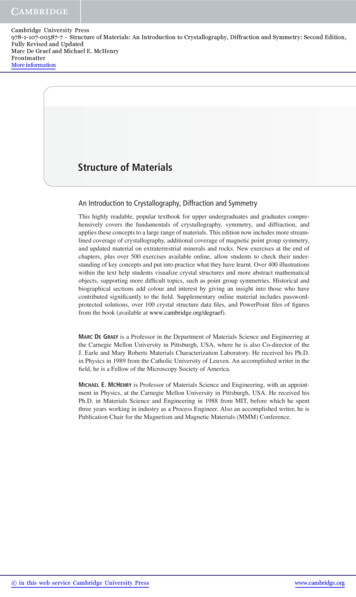
φ 2πλδ 2πλd sin θ(14.3.9)Assuming that both fields point in the same direction, the total electric field may beobtained by using the superposition principle discussed in Section 13.4.1:φ φ E E1 E2 E0 [sin ωt sin(ωt φ ) ] 2 E0 cos sin ωt 2 2 (14.3.10)where we have used the trigonometric identity α βsin α sin β 2sin 2 α β cos 2 (14.3.11)The intensity I is proportional to the time average of the square of the total electric field:orφ φ φ I E 2 4 E0 2 cos 2 sin 2 ωt 2 E0 2 cos 2 2 2 2 (14.3.12) φ I I 0 cos 2 2 (14.3.13)where I 0 is the maximum intensity on the screen. Upon substituting Eq. (14.3.4), theabove expression becomes π d sin θ I I 0 cos 2 λ (14.3.14)Figure 14.3.2 Intensity as a function of d sin θ / λFor small angle θ , using Eq. (14.2.5) the intensity can be rewritten as πdI I 0 cos 2 λL y (14.3.15)14-10
Example 14.2: Intensity of Three-Slit InterferenceSuppose a monochromatic coherent source of light passes through three parallel slits,each separated by a distance d from its neighbor, as shown in Figure 14.3.3.Figure 14.3.3 Three-slit interference.The waves have the same amplitude E0 and angular frequency ω , but a constant phasedifference φ 2π d sin θ / λ .(a) Show that the intensity isII 09 2π d sin θ 1 2 cos λ 2(14.3.16)where I 0 is the maximum intensity associated with the primary maxima.(b) What is the ratio of the intensities of the primary and secondary maxima?Solutions:(a) Let the three waves emerging from the slits beE1 E0 sin ω t , E2 E0 sin (ω t φ ) , E3 E0 sin (ω t 2φ )(14.3.17)Using the trigonometric identity α βsin α sin β 2 cos 2 α β sin 2 (14.3.18)the sum of E1 and E3 isE1 E3 E0 sin ω t sin (ωt 2φ ) 2 E0 cos φ sin(ω t φ )(14.3.19)The total electric field at the point P on the screen is14-11
E E1 E2 E3 2 E0 cos φ sin(ωt φ ) E0 sin(ω t φ ) E0 (1 2cos φ )sin(ω t φ )(14.3.20)where φ 2π d sin θ / λ . The intensity is proportional to E 2 :I E (1 2 cos φ ) sin (ωt φ )2022E022 (1 2 cos φ )2(14.3.21)where we have used sin 2 (ω t φ ) 1/ 2 . The maximum intensity I 0 is attained whencos φ 1 . Thus,I (1 2 cos φ ) I092(14.3.22)which impliesII 2 2π d sin θ I 0 (1 2 cos φ ) 0 1 2 cos 99 λ 2(14.3.23)(b) The interference pattern is shown in Figure 14.3.4.From the figure, we see that the minimum intensity is zero, and occurs whencos φ 1/ 2 . The condition for primary maxima is cos φ 1 , which gives I / I 0 1 . Inaddition, there are also secondary maxima which are located at cos φ 1 . The conditionimplies φ (2m 1)π , or d sin θ / λ (m 1/ 2), m 0, 1, 2,. The intensity ratio isI / I 0 1/ 9 .14-12
14.4 DiffractionIn addition to interference, waves also exhibit another property – diffraction, which is thebending of waves as they pass by some objects or through an aperture. The phenomenonof diffraction can be understood using Huygens’s principle which states thatEvery unobstructed point on a wavefront will act a source of secondary spherical waves.The new wavefront is the surface tangent to all the secondary spherical waves.Figure 14.4.1 illustrates the propagation of the wave based on Huygens’s principle.Figure 14.4.1 Propagation of wave based on Huygens’s principle.According to Huygens’s principle, light waves incident on two slits will spread out andexhibit an interference pattern in the region beyond (Figure 14.4.2a). The pattern is calleda diffraction pattern. On the other hand, if no bending occurs and the light wave continueto travel in straight lines, then no diffraction pattern would be observed (Figure 14.4.2b).Figure 14.4.2 (a) Spreading of light leading to a diffraction pattern. (b) Absence ofdiffraction pattern if the paths of the light wave are straight lines.We shall restrict ourselves to a special case of diffraction called the Fraunhoferdiffraction. In this case, all light rays that emerge from the slit are approximately parallelto each other. For a diffraction pattern to appear on the screen, a convex lens is placedbetween the slit and screen to provide convergence of the light rays.14.5 Single-Slit DiffractionIn our consideration of the Young’s double-slit experiments, we have assumed the widthof the slits to be so small that each slit is a point source. In this section we shall take thewidth of slit to be finite and see how Fraunhofer diffraction arises.14-13
Let a source of monochromatic light be incident on a slit of finite width a, as shown inFigure 14.5.1.Figure 14.5.1 Diffraction of light by a slit of width a.In diffraction of Fraunhofer type, all rays passing through the slit are approximatelyparallel. In addition, each portion of the slit will act as a source of light waves accordingto Huygens’s principle. For simplicity we divide the slit into two halves. At the firstminimum, each ray from the upper half will be exactly 180 out of phase with acorresponding ray form the lower half. For example, suppose there are 100 point sources,with the first 50 in the lower half, and 51 to 100 in the upper half. Source 1 and source 51are separated by a distance a / 2 and are out of phase with a path difference δ λ / 2 .Similar observation applies to source 2 and source 52, as well as any pair that are adistance a / 2 apart. Thus, the condition for the first minimum isaλsin θ 22orsin θ λa(14.5.1)(14.5.2)Applying the same reasoning to the wavefronts from four equally spaced points adistance a / 4 apart, the path difference would be δ a sin θ / 4 , and the condition fordestructive interference issin θ 2λa(14.5.3)The argument can be generalized to show that destructive interference will occur whena sin θ mλ , m 1, 2, 3, . (destructive interference)(14.5.4)Figure 14.5.2 illustrates the intensity distribution for a single-slit diffraction. Note thatθ 0 is a maximum.14-14
Figure 14.5.2 Intensity distribution for a single-slit diffraction.By comparing Eq. (14.5.4) with Eq. (14.2.5), we see that the condition for minima of asingle-slit diffraction becomes the condition for maxima of a double-slit interferencewhen the width of a single slit a is replaced by the separation between the two slits d. Thereason is that in the double-slit case, the slits are taken to be so small that each one isconsidered as a single light source, and the interference of waves originating within thesame slit can be neglected. On the other hand, the minimum condition for the single-slitdiffraction is obtained precisely by taking into consideration the interference of wavesthat originate within the same slit.Example 14.3: Single-Slit DiffractionA monochromatic light with a wavelength of λ 600 nm passes through a single slitwhich has a width of 0.800 mm.(a) What is the distance between the slit and the screen be located if the first minimum inthe diffraction pattern is at a distance 1.00 mm from the center of the screen?(b) Calculate the width of the central maximum.Solutions:(a) The general condition for destructive interference issin θ mλam 1, 2, 3, .For small θ , we employ the approximation sin θ tan θ y / L , which yieldsyλ mLa14-15
The first minimum corresponds to m 1 . If y1 1.00 mm , thenL 4 3ay1 ( 8.00 10 m )(1.00 10 m ) 1.33 mmλ1( 600 10 9 m )(b) The width of the central maximum is (see Figure 14.5.2)w 2 y1 2 (1.00 10 3 m ) 2.00 mm14.6 Intensity of Single-Slit DiffractionHow do we determine the intensity distribution for the pattern produced by a single-slitdiffraction? To calculate this, we must find the total electric field by adding the fieldcontributions from each point.Let’s divide the single slit into N small zones each of width y a / N , as shown inFigure 14.6.1. The convex lens is used to bring parallel light rays to a focal point P on thescreen. We shall assume that y λ so that all the light from a given zone is in phase.Two adjacent zones have a relative path length δ y sin θ . The relative phase shift βis given by the ratio β δ y sin θ ,2π λλ β 2πλ y sin θ(14.6.1)Figure 14.6.1 Single-slit Fraunhofer diffractionSuppose the wavefront from the first point (counting from the top) arrives at the point Pon the screen with an electric field given byE1 E10 sin ωt(14.6.2)The electric field from point 2 adjacent to point 1 will have a phase shift β , and thefield is14-16
E2 E10 sin (ωt β )(14.6.3)Since each successive component has the same phase shift relative the previous one, theelectric field from point N isEN E10 sin (ωt ( N 1) β )(14.6.4)The total electric field is the sum of each individual contribution:E E1 E2 EN E10 sin ωt sin (ωt β ) sin (ωt ( N 1) β ) (14.6.5)Note that total phase shift between the point N and the point 1 isβ N β 2πλN y sin θ 2πλa sin θ(14.6.6)where N y a . The expression for the total field given in Eq. (14.6.5) can be simplifiedusing some algebra and the trigonometric relationcos(α β ) cos(α β ) 2sin α sin β(14.6.7)[See Appendix for alternative approaches to simplifying Eq. (14.6.5).] To use the abovein Eq. (14.6.5), considercos(ωt β / 2) cos(ωt β / 2) 2sin ωt sin( β / 2)cos(ωt β / 2) cos(ωt 3 β / 2) 2sin(ωt β ) sin( β / 2)cos(ωt 3 β / 2) cos(ωt 5 β / 2) 2sin(ωt 2 β ) sin( β / 2)(14.6.8)cos[ωt ( N 1/ 2) β ] cos[ωt ( N 3 / 2) β ] 2sin[ωt ( N 1) β ]sin( β / 2)Adding the terms and noting that all but two terms on the left cancel leads tocos(ωt β / 2) cos[ωt ( N 1/ 2) β ] 2sin( β / 2) sin ωt sin (ωt β ) sin (ωt ( N 1) β ) (14.6.9)The two terms on the left combine tocos(ωt β / 2) cos[ωt ( N 1/ 2) β ] 2sin(ωt ( N 1) β / 2) sin( N β / 2)(14.6.10)with the result that14-17
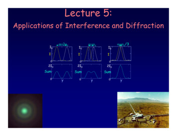
sin ωt sin (ωt β ) sin (ωt ( N 1) β ) sin[ωt ( N 1) β / 2]sin( β / 2) sin( β / 2)(14.6.11)The total electric field then becomes sin( β / 2) E E10 sin (ωt ( N 1) β / 2 ) sin( β / 2) (14.6.12)The intensity I is proportional to the time average of E 2 :2E2 sin( β / 2) sin( β / 2) 1sin 2 (ωt ( N 1) β / 2 ) E102 E 2 sin( β / 2) sin( β / 2) 2210(14.6.13)and we express I asI sin( β / 2) I 02 N sin( β / 2) 2(14.6.14)where the extra factor N2 has been inserted to ensure that I 0 corresponds to the intensityat the central maximum β 0 (θ 0) . In the limit where β 0 ,N sin( β / 2) N β / 2 β / 2(14.6.15)and the intensity becomes sin ( β 2 ) sin (π a sin θ / λ ) I I0 I0 β /2 π a sin θ / λ 22(14.6.16)In Figure 14.6.2, we plot the ratio of the intensity I / I 0 as a function of β / 2 .Figure 14.6.2 Intensity of the single-slit Fraunhofer diffraction pattern.14-18
From Eq. (14.6.15), we readily see that the condition for minimum intensity isπa sin θ mπ , m 1, 2, 3, . .λorλsin θ m , m 1, 2, 3, .a(14.6.17)In Figure 14.6.3 the intensity is plotted as a function of the angle θ , for a λ anda 2λ . We see that as the ratio a / λ grows, the peak becomes narrower, and more lightis concentrated in the central peak. In this case, the variation of I 0 with the width a isnot shown.Figure 14.6.3 Intensity of single-slit diffraction as a function of θ for a λ and a 2λ .14.7 Intensity of Double-Slit Diffraction PatternsIn the previous sections, we have seen that the intensities of the single-slit diffraction andthe double-slit interference are given by: sin (π a sin θ / λ ) I I0 π a sin θ / λ 2 φ π d sin θ I I 0 cos 2 I 0 cos 2 λ 2 single-slit diffractiondouble-slit interferenceSuppose we now have two slits, each having a width a, and separated by a distance d .The resulting interference pattern for the double-slit will also include a diffraction patterndue to the individual slit. The intensity of the total pattern is simply the product of thetwo functions:14-19
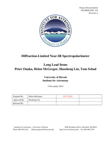
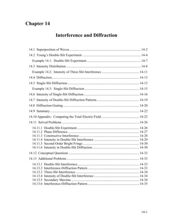
π d sin θI I 0 cos λ 2 sin (π a sin θ / λ ) π a sin θ / λ 2(14.7.1)The first and the second terms in the above equation are referred to as the “interferencefactor” and the “diffraction factor,” respectively. While the former yields the interferencesubstructure, the latter acts as an envelope which sets limits on the number of theinterference peaks (see Figure 14.7.1).Figure 14.7.1 Double-slit interference with diffraction.We have seen that the interference maxima occur when d sin θ mλ . On the other hand,the condition for the first diffraction minimum is a sin θ λ . Thus, a particularinterference maximum with order number m may coincide with the first diffractionminimum. The value of m may be obtained as:d sin θ mλ a sin θλorm da(14.7.2)Since the mth fringe is not seen, the number of fringes on each side of the central fringe ism 1 . Thus, the total number of fringes in the central diffraction maximum isN 2(m 1) 1 2m 1(14.7.3)14.8 Diffraction GratingA diffraction grating consists of a large number N of slits each of width a and separatedfrom the next by a distance d , as shown in Figure 14.8.1.14-20
Figure 14.8.1 Diffraction gratingIf we assume that the incident light is planar and diffraction spreads the light from eachslit over a wide angle so that the light from all the slits will interfere with each other. Therelative path difference between each pair of adjacent slits is δ d sin θ , similar to thecalculation we made for the double-slit case. If this path difference is equal to an integralmultiple of wavelengths then all the slits will constructively interfere with each other anda bright spot will appear on the screen at an angle θ . Thus, the condition for the principalmaxima is given byd sin θ mλ , m 0, 1, 2, 3, .(14.8.1)If the wavelength of the light and the location of the m-order maximum are known, thedistance d between slits may be readily deduced.The location of the maxima does not depend on the number of slits, N. However, themaxima become sharper and more intense as N is increased. The width of the maximacan be shown to be inversely proportional to N. In Figure 14.8.2, we show the intensitydistribution as a function of β / 2 for diffraction grating with N 10 and N 30 . Noticethat the principal maxima become sharper and narrower as N increases.(a)(b)Figure 14.8.2 Intensity distribution for a diffraction grating for (a) N 10 and (b)N 30 .14-21
The observation can be explained as follows: suppose an angle θ ( recall thatβ 2π a sin θ / λ ) which initially gives a principal maximum is increased slightly, ifthere were only two slits, then the two waves will still be nearly in phase and producemaxima which are broad. However, in grating with a large number of slits, even thoughθ may only be slightly deviated from the value that produces a maximum, it could beexactly out of phase with light wave from another slit far away. Since grating producespeaks that are much sharper than the two-slit system, it gives a more precisemeasurement of the wavelength.14.9 Summary Interference is the combination of two or more waves to form a composite wavebased on the superposition principle. In Young’s double-slit experiment, where a coherent monochromatic lightsource with wavelength λ emerges from two slits that are separated by a distanced, the condition for constructive interference isδ d sin θ mλ , m 0, 1, 2, 3, . (constructive interference)where m is called the order number. On the other hand, the condition fordestructive interference is1 d sin θ m λ , m 0, 1, 2, 3, . (destructive interference)2 The intensity in the double-slit interference pattern is π d sin θ I I 0 cos 2 λ where I 0 is the maximum intensity on the screen. Diffraction is the bending of waves as they pass by an object or through anaperture. In a single-slit Fraunhofer diffraction, the condition for destructiveinterference isλsin θ m , m 1, 2, 3,. (destructive interference)awhere a is the width of the slit. The intensity of the interference pattern is14-22
sin ( β 2 ) sin (π a sin θ / λ ) I I0 I0 β /2 π a sin θ / λ 22where β 2π a sin θ / λ is the total phase difference between waves from theupper end and the lower end of the slit, and I 0 is the intensity at θ 0 . For two slits each having a width a and separated by a distance d , theinterference pattern will also include a diffraction pattern due to the single slit,and the intensity is π d sin θ sin (π a sin θ / λ ) I I 0 cos λ π a sin θ / λ 2214.10 Appendix: Computing the Total Electric FieldSection 14.6 we used a trigonometric relation and obtained the total electric field for asingle-slit diffraction. Below we show two alternative approaches of how Eq. (14.6.5)can be simplified.(1) Complex representation:The total field E may be regarded as a geometric series. From the Euler formula (ix) n( 1) n x 2 n( 1) n x 2 n 1e i cos x i sin x(2n)!n 0 n !n 0n 0 (2n 1)!(14.10.1)sin x Im(eix )(14.10.2)ix we may writewhere the notation “ Im ” stands for the imaginary part. Thus, we havesin ωt sin (ωt β ) . sin (ωt ( N 1) β ) Im eiωt ei (ωt β ) . ei (ωt ( N 1) β ) Im eiωt (1 ei β . ei ( N 1) β ) iωt 1 eiN β iωt eiN β / 2 (eiN β / 2 e iN β / 2 ) Im e Im e ei β / 2 (ei β / 2 e i β / 2 ) 1 ei β sin( β / 2) sin( β / 2) Im ei (ωt ( N 1) β / 2) sin (ωt ( N 1) β / 2 ) sin( β / 2) sin( β / 2) (14.10.3)where we have used14-23
N an 1 a a2 n 01 a n 1,1 a a 1(14.10.4)The total electric field then becomes sin( β / 2) E E10 sin (ωt ( N 1) β / 2 ) sin( β / 2) (14.10.5)which is
22 rr21 ()r2 r1(r2 r1) 2drsinθ (14.2.3) In the limit L, i.e., the distance to the screen is much greater than the distance between the slits, the sum of and may be approximated by d r1 r2 rr12 2r, and the path difference becomes δ rr21 dsinθ (14.2.4) In this limit, the two rays