Transcription
EML 4905 Senior Design ProjectA B.S. THESISPREPARED IN PARTIAL FULFILLMENT OF THEREQUIREMENT FOR THE DEGREE OFBACHELOR OF SCIENCEINMECHANICAL ENGINEERINGHighway Wind TurbinesBruce ChampagnieGeatjens AltenorAntonia SimonisAdvisor: Dr.BoeslApril 12, 2013This B.S. thesis is written in partial fulfillment of the requirements in EML4905. The contents represent the opinion of the authors and not theDepartment of Mechanical and Materials Engineering.
Ethics Statement and SignaturesThe work submitted in this B.S. thesis is solely prepared by a team consisting of BRUCECHAMPAGNIE, GEATJENS ALTENOR, and ANTONIA SIMONIS and it is original. Excerptsfrom others’ work have been clearly identified, their work acknowledged within the textand listed in the list of references. All of the engineering drawings, computer programs,formulations, design work, prototype development and testing reported in this documentare also original and prepared by the same team of students.Antonia SimonisBruce ChampagnieGeatjens AltenorTeam LeaderTeam MemberTeam MemberDr. BoeslFaculty Advisorii
TABLE OF CONTENTSList of Figures . ivAbstract . 1Introduction . 2Design Challenges . 2Global Applications . 3Problem Statement . 4Motivation and Objective . 4Project Timeline . 5Literature Survey. 7Conceptual Design (Design Alternatives) . 8Analytical Analysis . 11Proposed Design . 11Major Components . 13Cost Analysis. 14Prototype Design and Testing . 14Conclusion . 16References . 17iii
LIST OF FIGURESFigure 1: Global Trend in Wind Energy, data from the global wind energy counciL . 3Figure 2 Project TimeLine. 5Figure 3: Breakdown of tasks . 6Figure 4: Computer Simulation of Highway Wind Turbine, India . 7Figure 5: Mechanical Engineering Students in India Display Highway Wind Turbine . 8Figure 6: Mark Oberholzer, Guardrail Wind TUrbine Design . 9Figure 7: Hong Kong University and Lucien Gambarota of Motorwave Ltd. . 9Figure 8: Arizona State University Student Design . 9Figure 9: Arizona State University Student Realistic Design. 10Figure 10: Preliminary solidworks Design . 13Figure 11: Ballpark Costs of Vertical Wind Turbine Components . 14iv
ABSTRACTThe objective of the project is to design a wind turbine to recapture wind energyfrom vehicles on the highway. Wind energy is considered the fastest growing clean energysource however; it is limited by variable natural wind. Highways can provide aconsiderable amount of wind to drive a turbine due to high vehicle traffic. This energy isunused.Extensive research on wind patterns is required to determine the average velocityof the wind created by oncoming vehicles. The wind turbines will be placed on the medianstherefore fluid flow from both sides of the highway will be considered in the design. Usingall of the collected data, existing streetlights on the medians can be fitted with these windturbines. Additionally, since the wind source will fluctuate, a storage system for the powergenerated will be designed to distribute and maintain a constant source of power. Ideally,the turbine can be used globally as an unlimited power source for streetlights and otherpublic amenities.1
INTRODUCTIONWind energy is the fastest growing source of clean energy worldwide. A major issuewith the technology is fluctuation in the source of wind. There is a near constant source ofwind power on the highways due to rapidly moving vehicles. The motivation for thisproject is to contribute to the global trend towards clean energy in a feasible way.DESIGN CHALLENGESThe price of turbines is increasing in accordance with the rising cost of energy andcommodities. The cost of designing the turbine, calculated in energy savings must berecovered in a reasonable time period.Each vehicle on the highway offers an intermittent and uncontrolled source of windpower. The design of the wind turbine must include storage of power and a system todistribute the generated power effectively.Operational noise level and space are other important design considerations. Thewind turbines should have as little negative impact on the placement location as possible.Wind turbines are traditionally used in remote locations. This offers the additionalchallenge of having to transport the power generated to the location wherein it will beutilized. Fortunately, the wind turbine in this project is designed for use in high traffic areaswhere the demand for power is high.Safety is another major design consideration. The turbines must be placed in hightraffic areas therefore several safety provisions are incorporated into the design. Thesesafety measures include stationary highway guards surrounding the rotating turbineblades and warning labels.2
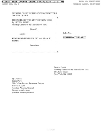
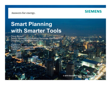
GLOBAL APPLICATIONSThe design can be used in any city around the world. It should be environmentallyfriendly. Labels in various languages and manuals will be provided for each specific city.Figure 1 shows a dramatic increase in the eemploymentmployment of wind energy globally. Windpower increased by nearly 20% in 2012 reaching a new peak of 282 GW. Various sourcessuch as the Global Wind Energy Council show China as the leading country in theemployment of Wind energy.FIGURE 1: GLOBAL TREND IN WIND ENERGY, DATA FROM THE GLOBAL WIND ENERGY COUNCIL3
PROBLEM STATEMENTA major hindrance in the growth of wind energy is fluctuation in the sources ofwind. Highways appear to be a sufficient source of potential wind energy. An in-depthanalysis of fluid flow due to traffic on highways must be performed to acquire boundarylimits for the wind turbine design. The turbine must be able to store energy for use whenthere is low traffic, bumper to bumper or stop and go traffic.The design must besustainable and environmentally friendly.MOTIVATION AND OBJECTIVEThe motivation for designing a highway wind turbine is to contribute towards theglobal trend in wind energy production in a feasible way. Wind turbines are traditionallyemployed in rural areas, the goal of this project is to design a wind turbine that can be usedin cities. In particular, the turbines will use the wind draft created by vehicles on thehighway to generate electricity. The idea is to offset the amount of pollution created byburning fossil fuels by introducing a potential source of clean energy.4
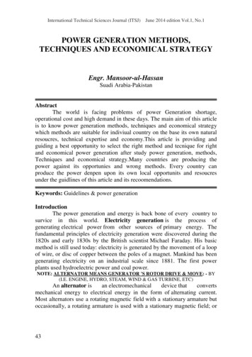
PROJECT TIMELINEThe project is divided into several major tasks. Research is a significant portion ofthis project because collecting our own data requires special permissions and maybe a bithazardous. Data is collected from the Department of Transportation and the CivilEngineering Department at FIU. All of the team members are expected to research the prosand cons of the different design options to ensure the most efficient design. Thepreliminary Solidworks design of the highway wind turbine is updated with newinformation.FIGURE 2 PROJECT TIMELINE5
TaskMember (s)HoursProject OverviewAll membersProposed DesignDesign SurveyBruce Champagnie andAntonia SimonisBruce ChampagniePreliminary SketchesSolidworks DesignBruce ChampagnieGeatjensAltenorResearch and Data AnalysisAll membersCost AnalysisGeatjensAltenor5Material SelectionSolidworksSimulationsBruce ChampagnieAntonia Simonis58Design PrototypeAll members48Testing PrototypeAll members48Optimize PrototypeAll members2461152550FIGURE 3: BREAKDOWN OF TASKSAll team members are expected to participate in the research and design of thehighway wind turbine. Team meetings are frequently held atleast once a week. BruceChampagnie has the most influence in collecting and analyzing relevant data relating to theturbine design. GeatjensAltenor is charged primarily with the solidworks rendering of theturbine. Antonia Simonis is in charge of simulating the completed model on solidworksbefore production of the prototype. Much of the work is performed as a team but these arethe areas where each individual made the most impact.6
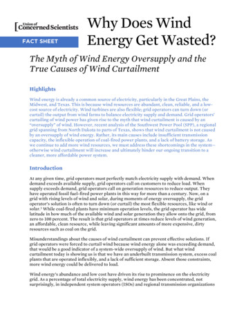
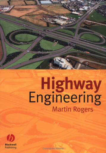
LITERATURE SURVEYThe idea to utilize wind turbines on the highway is not entirely unique. There havebeen attempts by several individuals and groups to recycle energy from highways. Themost impressive is a design displayed on a YouTube video entitled “Highway Helical WindTurbine Project (Next Generation Highway's Potential For Wind Power).” In the video agroup of Mechanical Engineering Students from YCET Kollam, Kerala display a prototype oftheir highway wind turbine as seen in Figures 4 and 5.FIGURE 4: COMPUTER SIMULATION OF HIGHWAY WIND TURBINE, INDIAFigure 4 is a video still of a computer animated design of a highway wind turbineproposed by Mechanical Engineering Students in India. In Figure 5, the students Nabeel B,Firoz khan T S, Krishnaraj V, Kannan Raj, Arun S, Shaiju mon T K, and Akhil Ganeshdemonstrate a working prototype of their design. (Highway Helical Wind Turbine Project(NextGenerationHighway'sPotentialFor,2012)7
FIGURE 5: MECHANICAL ENGINEERING STUDENTS IN INDIA DISPLAY HIGHWAY WIND TURBINECONCEPTUAL DESIGN (DESIGN ALTERNATIVES)There are several ways to approach this particular design problem. Inliteraturesurveys, we discovered different features of wind turbines which were appealing fordifferent reasons. For example, the gear turbines in China were very inexpensive and themodular sections could easily be snapped together to form a bigger system. That particulardesign did not seem as environmentally friendly as the designs with larger propellers.Other designs include turbines built into highway dividers or on overhead poles as seen inthe design by the Arizona State Student Joe (last name not provided) (Joe, 2007). Joecalculated that with cars moving at 70 mph, 9,600 kilowatts of electricity could beproduced per year using his design.8
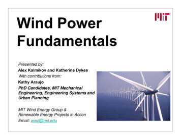
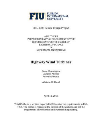
FIGURE 6: MARK OBERHOLZER, GUARDRAIL WIND TURBINE DESIGNFIGURE 7: HONG KONG UNIVERSITY AND LUCIEN GAMBAROTA OF MOTORWAVE LTD.FIGURE 8: ARIZONA STATE UNIVERSITY STUDENT DESIGN9
FIGURE 9: ARIZONA STATE UNIVERSITY STUDENT REALISTIC DESIGNFigures 6-9show various designs for wind turbines on the highway. Each design haspositive and negative aspects.For example, in figure 6, the turbines are built intoguardrails. This design is particularly complex because the guardrails must be fitted withvanes in order for the wind produced by vehicles to reach the turbines inside. Figure 7shows an inexpensive wind turbine design. This design was not selected due to safetyconsiderations. The parts are small and can easily be snapped out of place. Figures 8 and 9show wind turbines proposed by an Arizona State University student. This design isrejected because it requires the construction of custom support posts.10
ANALYTICAL ANALYSISThe following formulas are utilized to design the most efficient turbine.Power available 1/2ρAV 3The power coefficient (CP) is the power extracted divided by the power available 1/2!"# 3The maximum value for the power coefficient is called the Betz limit max &)* ,'(').,/0 12 0.5926Now the maximum m power that can be extracted from a given wind stream is defined bywhat is known as the Betz limit, therefore, the power extracted is calculated by thefollowing equation. 1/2Cp!"# 3Where V is the wind velocity and! is the fluid density. These equations show that velocityis the most significant factor in generating power. Power is directly proportional to thecubed velocity of the wind.PROPOSED DESIGNOur group is proposing to design a vertical axis wind turbine to utilize the windproduced by moving vehicles to generate electricity. These turbines will be placed alongroadways that have high volume of fast moving traffic. The electricity generated will thenbe the stored in batteries. Since the electricity produced will be direct current (DC) it mustbe converted to alternating current (AC) before it can be used for lighting the street lamps,sold to the grid or any of the man ways we use electricity today. This means that the DCcurrent must be pasted through an inverter first before it is usedFigure 8shows a sample11
vertical axis wind turbine with part labels however; the turbine we are designing will likelyreflect the design in Figure9 by TAK studios.FIGURE 8: LABELED PARTS OF A VERTICAL WIND TURBINEFIGURE 9: TAK STUDIO DESIGNThere are several advantages and disadvantages to using a vertical wind turbinedesign. A vertical wind turbine design is selected because vertical turbines are capable ofcapturing wind in any direction, whereas, horizontal turbines need to be pointed in the direction12
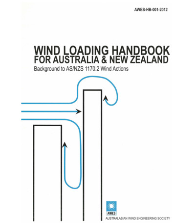
of the wind. Additionally, heavy parts such as the generator and battery can easily be placed atthe base of the turbine.MAJOR COMPONENTSFigure 8 shows the major components of a vertical wind turbine. The blades are themost difficult part of the design because they must be propelled by wind in any direction.This necessitates that the blades are curved and angled so that as much surface area isexposed to the wind draft from oncoming vehicles as possible. The blades must also belightweight. The central column design is relatively simple. It is a hollow tube whereon theblades will be attached. It should be large enough to accommodate the width of streetlights.FIGURE 10: PRELIMINARY SOLIDWORKS DESIGNFigure 10 shows the preliminary Solidworks rendering by GeatjensAltenor. The ideais to curve and angle the blades to capture the maximum amount of wind.13
To produce this product we hope to find existing parts that fit within the designcriteria and manufactureparts significant to the design. We will be doing a series ofcalculations in order to determine wind is needed to turn the turbines sufficient enough togenerate an adequate amount of electricity. Data will be collected to determine the trafficpatterns and energy storage requirements. Efficient placement is important so that theycan harvest maximum energy from the wind draft created by automobiles.COST ANALYSISWe do not have a sponsor for this project therefore the costs is divided amonggroup members. Average cost of some turbine parts are listed in Figure 11 shows averagecosts of several of the major components in a vertical wind turbine. To reduce costs, someof the components will be manufactured such as the wind turbine blades.FIGURE 11: BALLPARK COSTS OF VERTICAL WIND TURBINE COMPONENTSPROTOTYPE DESIGN AND TESTINGUsing the research and data collected, a scale solid works model is designed.Simulations are performed for different materials and loading conditions. From thisanalysis, the material for the prototype is selected.The turbine blades are made of durable lightweight material. A mold is created andused to produce all 3 blades. The shaft is made from PVC pipe. The generator, alternator,batteries and other components are bought.14
The model is exposed to wind created by a fan at the approximate speed of winddrafts created by vehicles for testing. Experimental data on the power generated iscompared to theoretical data.15
CONCLUSIONConclusively, extensive data is collected on wind patterns produced by vehicles onboth sides of the highway. Using the collected data, a wind turbine is designed to be placedon the medians of the highway. Although one turbine may not provide adequate powergeneration, a collective of turbines on a long strip of highway has potential to generate alarge amount of energy that can be used to power streetlights, other public amenities oreven generate profits by selling the power back to the grid. This design concept is meant tobe sustainable and environmentally friendly. Additionally, a wind turbine powered byartificial wind has a myriad of applications. Theoretically any moving vehicle can power theturbine such as an amusement park ride. The highway wind turbine can be used to providepower in any city around the globe where there is high vehicle traffic.16
REFERENCESHighway Helical Wind Turbine Project (Next Generation Highway's Potential For. (2012,November 20). (Department of Mechanical Engineering YCET Kollam. tp://www.youtube.com/watch?v igures/wind-energy-global-status/Joe. (2007, April 11). Archinect. Retrieved March 15, 2013, from Arizona State University(Joe): es-please-commentAlternative Energy Systems and Application Mississippi State UniversityB.K Hodge January 2009, John Wiley & Sons Inc.17
The design of the wind turbine must include storage of power and a system to distribute the generated power effectively. Operational noise level and space are other important design considerations. The wind turbines should have as little negative impact on the placement location as possible. Wind