Transcription
Section IVIMAGINGPROCEDURES andPROTOCOLSCHAPTER 19 Neurologic ImagingProceduresCHAPTER 20 Thoracic Imaging ProceduresCHAPTER 21 Abdomen and Pelvis ImagingProceduresCHAPTER 22 Musculoskeletal ImagingProceduresCHAPTER 23 Interventional CT and CTFluoroscopyCHAPTER 24 PET/CT Fusion ImagingINTRODUCTIONEach imaging facility has its own, often unique, set ofexamination protocols. For any given CT examination, theprotocol will vary according the individual requirementof the imaging site. Factors that influence a specific site’sprotocol parameters include the type of equipmentavailable (e.g., 64-slice versus 16-slice), the setting(e.g., inpatient versus outpatient), and the particularpreferences of the radiologists in charge. Like all fieldsof medicine, CT is constantly evolving so it followsthat examination protocols constantly undergo reevaluation and refinement. A cookbook approach to CTscanning is impractical as it cannot possibly account forall possible variables. The protocols presented in thissection are intended as examples of just a few of themany possible variations in current practice. There hasbeen no attempt to survey institutions to determine themost prevalent protocols; protocols included here shouldnot be considered either the most common or the best.They are simply one or two options among many. Manyother protocol options can be found on the World WideWeb, posted by both equipment manufacturers andvarious university hospitals. The protocols in this textare in a tabular format to facilitate easy reference. Whenpossible, the protocols include parameter variationsfor a 16- and a 64-detector system. Again, these areintended be illustrative, providing the reader an ideaof the parameters most likely to be adjusted whenswitching from one type of detector configuration237Chap19.indd 23710/9/2009 2:41:02 PM
238Computed Tomography for Technologists: A Comprehensive Textto another. Unless otherwise noted, protocols thatinclude intravenous contrast enhancement use a 300concentration, low-osmolality agent.CT imaging increasingly relies on the integration ofa variety of knowledge and skills. The first three sectionsof this text provide information on physics, patient care,and cross-sectional anatomy necessary to understand andcarry out CT examination protocols. Hence, this section isintended to be a culmination of the sections that precedeit. Within most categories of the examination protocols,one or two topics have been selected for expositorywriting. These essays are included to demonstrate theinterdependency of the information provided in previoussections and to encourage the reader to assemble theknowledge gained thus far into a cohesive whole. Readerswill notice that these essays provide information that isnot strictly necessary to know to perform a high-qualityexamination. However, both new and seasoned CTtechnologists will appreciate the “extra” information, such asthe signs and symptoms of various diseases and conditions,as these are so often observed in clinical practice.ROUTINE SCANNING PROCEDURESAlthough in actual practice there are exceptions to everyrule, some standards of practice are assumed. We startwith a discussion of these assumptions.In all routine studies, one or two reference images(called “scouts” by some manufacturers) are acquiredbefore scanning. The optimal reference image includesall areas to be scanned and therefore ensures that theanatomy to be imaged is within the range of the scanner(see Chapter 5).Regardless of the type of scanner used, it isimperative that the operator input the correctdirectional instructions before scanning. This procedurerequires indicating whether the patient is placed heador feet first into the gantry and whether he or she islying supine, prone, or in the decubitus position. If theoperator accurately enters this information into thesystem, the software correctly annotates the image asto left-right, anterior-posterior, and superior-inferiororientation.After the scout image is obtained, the operatorselects the location of cross-sectional slices. Scanparameters such as mAs, kVp, display field of view,and reconstruction algorithm(s) are selected. Mostoften, a preprogrammed group of scan parameters isselected so that the technologist must make only minormodifications to suit the particular patient or clinicalindication.Chap19.indd 238It is important to correctly annotate the image as towhether contrast material is administered. All CT systemsallow a notation concerning the use of contrast agents.Often, the notation C is inputted after the introductionof contrast medium.Routine procedure for some CT examinationsincludes scanning without contrast material, thenrepeating the study with intravenous contrastenhancement. Some protocols call for repeating thestudy at different phases of contrast enhancement.Whenever possible, the repeat scans should be taken atthe same location as the unenhanced images.A history should be taken for all patients. Forexaminations that require contrast enhancement,the history must include allergies as well as any renalcomplications (see Chapter 11).Careful breathing instructions should be given to allpatients undergoing body scanning. Some manufacturerssuggest that technologists use a coaching procedureto increase the length of breath-hold for a helical study.This coaching requires the patient to take several deepbreaths before taking one final breath and holding it forthe maximum possible time, then exhaling slowly.After completing a CT study, it is standard procedureto include a scout image that is cross-referenced by lines.These lines represent the location of each cross-sectionalimage. It is also typical to include patient data at thebeginning or end of each examination. Data must thenbe stored in some fashion. The practice of transferringimages to film is dwindling, but by no means hasdisappeared. When picture, archive, and communicationsystems (PACS) are used, images must be transmittedto the appropriate radiologist’s workstation (Chapter9). This information may also be included in a facility’sexamination protocols.10/9/2009 2:41:06 PM
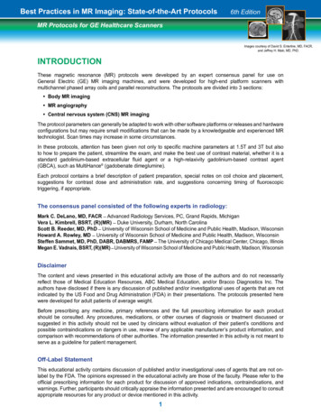
Chapter 19NEUROLOGICIMAGINGPROCEDURESKey Terms:supraorbital meatal line glabellomeatal line intracranialhemorrhage Valsalva maneuver splitbolus CT venography thrombolytictherapy completed or establishedstroke cerebrovascular accident strokein evolution progressivestroke ischemic hemorrhagic thrombotic embolic subarachnoidhemorrhagic stroke arteriovenousmalformations hypotensive stroke transientischemic attack (TIA) atrial fibrillation tissueplasminogen activator (t-PA) penumbra infarction CT brain perfusion rCBF rCBV MTT central volume principle basalganglia CVRCGENERAL IMAGING METHODS FOR THEHEADThe patient’s head is positioned in the head holder formost protocols of the head. Depending on the design of thehead holder, it can sometimes also be used for neck protocols. When the head holder is not used, a molded spongeis placed directly on the scan table and the patient’s headis positioned within the sponge. In all cases, the patientshould be made as comfortable as possible and immobilized as effectively as possible to prevent motion artifacton the images. This is often accomplished by placing smallChap19.indd 239wedge sponges on either side of the patient’s head. Inmost cases it is not necessary to ask the patient to suspendbreathing for CT studies of the head or neck. Anatomydisplayed in cross-sectional slices will look slightly different depending on the angulation used. The slice angle isdetermined by the position of the patient’s head (i.e., moving the chin up or down) and the angle of the gantry. Itwas once common to program the cross-sectional slices ofthe brain to be parallel to the orbitomeatal line; however,more recent practice favors using the supraorbital meatalline (also called the glabellomeatal line) to reduce radiation exposure to the lens of the eye. Figure 19-1 illustrateslines used for positioning. A disadvantage of many multidetector CT systems is that they do not allow the gantryto be tilted when in helical mode. Therefore, axial (stepand-shoot) techniques are often used for routine brainimaging.BOX 19–1Key C nceptRecent practice favors programming slices of the brain parallelto the supraorbital meatal line (rather than the orbital meatalline) to reduce radiation exposure to the lens of the eye.Changing the image plane from axial to coronal mayprovide additional information. There are two methods ofachieving a coronal position for head scanning. One is toplace the patient prone on the scanning table and ask thepatient to extend the chin forward. An alternative approachis to place the patient supine and ask him to drop his headback as far as possible. This position usually requires a specialized head holder. In either position, the slice plane willbe coronal. If the patient cannot extend the neck fully, the23910/9/2009 2:41:10 PM
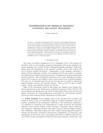
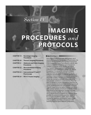
240Computed Tomography for Technologists: A Comprehensive TextSupraorbitalmeatalOrbitomeatalFIGURE 19-1 The basic localization points and planes usedin CT positioning.gantry may be angled to obtain a more coronal plane. Theimage obtained in either the prone or the supine coronalposition is essentially the same. Obviously the images areflipped inferior-superior. The preferred position involvesseveral factors, including patient comfort, radiologist preference, and the effect of gravity on anatomic structures(e.g., will fluid settle inferiorly or superiorly?).Imaging the posterior fossa of the brain is a challengein CT scanning. Because of the great difference in beamattenuation ability between the dense bone of the skulland the much less dense tissue of the brain, streak artifactsare common. This inherent limitation may be managedby decreasing slice thickness when scanning the posteriorfossa and increasing the kVp setting.BOX 19–2Key C nceptBecause of the dense bone of the skull, beam-hardeningartifact is common in the posterior fossa.Modern multislice CT scanners allow studies of thehead to be routinely acquired with thinner slices than inthe past—1.25 mm thickness is typical. These thin sliceshelp to reduce beam-hardening artifacts. Images are oftenmerged into thicker slices for viewing.In examinations of the head, the helical CT mode isused mainly for the purpose of generating three-dimensionalreformations or to minimize motion-related artifacts. Ingeneral, routine head studies are done using an axial mode,and CT angiography (CTA) studies of the head and neckare done using a helical mode.Cross-sectional slices of the brain are viewed in multiple window settings. Standard window settings includesoft-tissue (brain) 160/40 (approximate window width/window level) for slices in the posterior fossa, 100/30 forslices above; bone (particularly on trauma or postoperative patients) 2500/400; blood 200/60.Chap19.indd 240Narrow window widths are used to demonstratethe brain, as there is only a small difference in attenuation between the gray matter and the white matter(Chapter 4). Table 19-1 presents values of x-ray attenuation on unenhanced cranial CT. The slightly higherattenuation of the gray matter of the brain compared withwhite matter may be a result of both a lower gray matterwater content and a higher blood volume.1 Recall that onthe Hounsfield scale zero refers to pure water; the value ofcerebrospinal fluid (CSF) is slightly above that of water.CT is the most frequently used initial examination for imaging of intracranial hemorrhage (ICH). Theappearance of an ICH will change with the passage oftime. This is because the red blood cells within the hemorrhage begin to deteriorate within several hours afterleaving the vasculature. These changes are complex anddepend on many factors, such as whether the patient isanemic or whether, and to what degree, blood has mixedwith CSF. As a general rule, ICH will appear hyperdenseto normal brain tissue for approximately 3 days, afterwhich it will gradually decrease in density. This densityloss begins at the periphery of the hematoma. As densitydiminishes, portions of the hematoma become isodenseto brain tissue. This progressive density loss continuesuntil the entire hematoma finally becomes hypodense tobrain tissue. Although greatly simplified, ICH can be generally expected to appear hyperdense (i.e., white on theimage) from onset to 3 days; from 4 to 10 days it is likelyto contain a hyperdense center surrounded by concentricareas of hyperdense and hypodense tissue; from 11 daysto 6 months it is likely to contain an isodense center surrounded by areas of hypodense tissue; by 6 months theICH will be hypodense to brain2 (Fig. 19-2). It is not therole of the technologist to interpret images. However, it isimportant that technologists recognize certain potentiallycritical pathologic changes so that when present, theycan be brought to the attention of a radiologist. Althoughmost patients with an ICH are seen through the emergency department where images are reviewed by radiologists and reported on quickly, some patients, particularlythose with less acute presentations (e.g., headache) mayarrive in the CT department as outpatients. In these situations, the technologist can play a vital role by bringing theTABLE 19-1 X-ray Attenuation in Cranial CT(in Hounsfield Units)Gray matterWhite matterCerebrospinal fluidCirculating bloodClotted bloodTissue 11080–150–60 to –70–100010/9/2009 2:41:12 PM
Neurologic Imaging Procedures 7 Hours7 Hours – 3 Days4 – 10 Days11 Days – 6 Months241 6 MonthsOr Hyperdense to brain Isodense to brain Hypodense to brainFIGURE 19-2 A simplified schematic of the evolution of intracranial hemorrhage as it appears on CT.scan to the radiologist’s attention so that these patientsreceive prompt medical attention.CT is the primary imaging modality for emergentindications such as trauma and acute changes in neurologic status. For most applications concerning structuralimaging of the brain and skull base, nonenhanced CT isusually adequate. IV contrast administration is indicatedfor infection and neoplasm, but in practice this is not frequently performed because those indications most oftenprompt an MRI, obviating the need for enhanced CT.However, in some situations MRI is contraindicated (e.g.,patient with pacemakers) or unavailable, leaving enhancedCT the best diagnostic option.BOX 19–3Key C nceptIt is not the role of the technologist to interpret images.However, it is important that technologists recognize certainpotentially critical pathologic changes so that when present,they can be brought to the attention of a radiologist.NECK PROTOCOLSRoutine scanning of the neck is typically performed withthe patient supine and the neck slightly extended. It is mostoften performed in the helical mode. To reduce artifactsthat degrade images in the lower neck, the patient shouldbe instructed to lower the shoulders as much as possible.In some institutions images of the neck are acquired whilethe patient performs a modified Valsalva maneuver. Thismaneuver requires the patient to blow the cheeks out. Thistechnique helps to distend the pyriform sinuses. Anothertechnique that has been used to evaluate the aryepiglotticfolds and pyriform sinuses is to ask the patient to pronounce a prolonged “e” during scanning.Unless contraindicated, IV contrast media is usedwhen scanning the neck. The goals in CT scanningof the neck are to allow sufficient time after contrastadministration for mucosa, lymph nodes, and pathologic tissue to enhance, yet acquire images while theChap19.indd 241vasculature remains opacified.3 Scanning too early afterthe contrast media injection could result in certaintypes of neoplastic and inflammatory processes goingundetected. However, by delaying scan acquisition theinjected contrast agent will no longer opacify the vasculature. One strategy for addressing these contradictorygoals is a contrast injection technique referred to as asplit bolus. The total contrast dose is split, often in half.The first dose is given and a delay of about 2 minutes isobserved. This allows time for structures that are slowerto enhance to be opacified. The delay is followed by asecond bolus containing the remainder of the contrast;scanning is initiated soon after the second injectionis complete, using this second injection to more fullyopacify the vessels. The split bolus injection techniqueis also frequently used for maxillofacial studies in whichcontrast media is indicated.BOX 19–4Key C nceptUnless contraindicated, IV contrast media is used whenscanning the neck. The goals in CT scanning of the neck areto allow sufficient time after contrast administration formucosa, lymph nodes, and pathologic tissue to enhance, yetacquire images while the vasculature remains opacified.CTA OF THE HEAD AND NECKAdvances in multidetector CT systems and image postprocessing techniques have expanded the role that CTplays in the evaluation of cervicocranial vascular disease.Although cerebral catheter angiography or digital subtraction angiography (both performed in the interventionalradiology department) are still generally regarded as thegold standard for the imaging of cerebrovascular disorders,those techniques are time-consuming and are associatedwith a small, but significant, rate of permanent neurologiccomplications.4 CT angiography has the advantages ofbeing noninvasive and widely available. The time-savingnature of CTA over traditional angiography is particularly10/9/2009 2:41:13 PM
242Computed Tomography for Technologists: A Comprehensive Textimportant in the case of patients suspected of suffering anacute stroke in which treatment decisions must be madequickly (a more detailed discussion of stroke begins at theend of this page). In addition, cerebral CTA can be combined with brain perfusion imaging to assess the viabilityof brain parenchyma and its vascular supply. Cerebral andcarotid CTA techniques provide important informationabout vessel walls; three-dimensional postprocessing ofthe image data depicts the spatial relationship of complexvascular lesions to the surrounding structures, providing valuable information for the surgeon. Rapid, highresolution scans are taken while contrast is in the arterialenhancement phase. The goals of CTA for cervicocranial vascular evaluation can be summarized as follows:1) to accurately measure stenosis of the carotid and vertebral arteries and their branches, 2) to evaluate the circle ofWillis for completeness using three-dimensional reformations of cerebral vasculature in relation to other structures,and 3) to detect other vascular lesions, such as dissectionsor occlusions. A modification of CTA, called CT venography (CTV) is used for the depiction of venous anatomy.Scan parameters are quite similar to CTA, except imagesare acquired while contrast is in the venous enhancementphase.SPINE PROTOCOLSCompared with conventional radiography, CT examinations of the spine produce images with inherentlyhigh soft tissue contrast. This contrast permits the visualization of structures such as the intervertebral disks,ligaments, and muscle, as well as bone detail. Visualization of intradural structures is improved by the intrathecal administration of water-soluble contrast material(Chapter 12). CT examinations are performed aftermyelography to enhance or clarify myelographic findings of intradural and extradural abnormalities. MRIprovides even higher soft tissue sensitivity than CT, andin certain circumstances, it is the modality of choice forimaging the spine (e.g., multiple sclerosis, hydromyelia,syringomyelia). For some conditions, such as spinalstenosis, MRI is equivalent to CT. In some situations,CT is considered superior to MRI, such as in the evaluation of bony abnormalities of the spine.Scans of the spine are often obtained after intrathecalcontrast material is given for a fluoroscopic myelographystudy. Intrathecal contrast medium may be helpful for thediagnosis of degenerative disk disease and other disk diseases, such as extradural neoplasm. Most reports suggest adelay of 1 to 3 hours between the intrathecal injection andscanning. This delay allows the contrast material to dilute.If the scans are performed while the contrast material istoo dense, intradural structures may be masked. Rollingthe patient once or twice before scanning is recommendedto mix the contrast material that may have settled sincethe myelogram.Chap19.indd 242BOX 19–5Key C nceptWhen CT is performed after intrathecal contrast administration for fluoroscopic myelography, a delay of 1 to 3 hoursbetween the contrast injection and scanning is recommended. This delay allows the contrast material to becomesufficiently dilute.Proper localization is essential in scanning the spine.All studies should include scout images in both anteroposterior (AP) and lateral projections. The scouts will permit vertebral levels to be readily counted and classifiedto ensure that scans are taken at the appropriate levels.When scanning the lumbar spine, it is important to notewhether the patient has a sixth lumbar vertebra (an anatomic variant) that requires additional scans.SPECIFIC NEUROLOGIC PROTOCOLSConcepts learned in previous chapters can be applied toscanning the head, neck, and spine. Neurologic CT protocols are often designed to meets the needs of a specificstructure or organ (i.e., circle of Willis) or to adapt to aparticular clinical indication (i.e., suspected spinal arteriovenous malformation). Many factors must be consideredin the development of a scanning protocol. The following detailed discussion of stroke and CT brain perfusionis presented here to provide the reader with a broaderunderstanding of the many issues that may be taken intoconsideration in the design of CT protocols. Examples ofvarious protocols are provided at the end of the chapter.A Profile of StrokeIntroductionThe American Heart Association reports that cerebrovasculardisorders such as ischemic and hemorrhagic strokes constitute the third most frequent cause of death in North America.Equally alarming, stroke is the leading cause of long-term disability. Approximately 20 to 30% of stroke victims do notsurvive, and 55% of stroke survivors have a disability.5 Despitethe significant advances in the treatment of stroke in recentyears, cerebrovascular disorders continue to pose a considerable challenge to acute neurovascular management.Therapeutic options, such as thrombolytic therapy, canlimit the extent of brain injury and improve outcome afterstroke when administered to patients who fall within narrowclinical guidelines. Many of these therapies are only effectiveif given early after the stroke has begun, hence the criticalityof emergent imaging. However, these therapies are expensiveand may result in potentially life-threatening complications,drawbacks that make it crucial that each case be assessedby its individual risk-benefit ratio. Most important, the location and extent of the ischemic lesion, combined with theseverity of the blood flow reduction, are the main factorsthat predict outcome in the treatment of stroke.6 These10/9/2009 2:41:13 PM
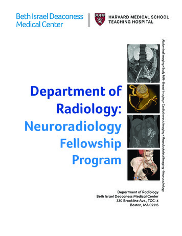
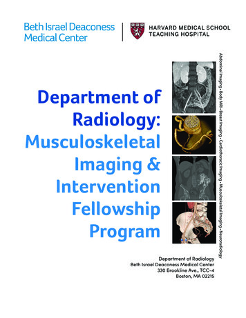
Neurologic Imaging Proceduresfactors demand an assessment of cerebral blood circulationto determine whether a conservative or a more aggressivetherapy is needed in the early stage of stroke.To adequately explain cerebrovascular disorders itis necessary to begin with an analysis of the basic physiologic processes that result in the origin and development of stroke. This review will define common terms, listsymptoms, and present risk factors. In the following section we discuss CT perfusion, a newer diagnostic option inthe assessment of acute stroke.OverviewAlthough the brain receives approximately 25% of thebody’s oxygen supply, the brain lacks the capacity for itsstorage. Brain cells require a constant supply of oxygento maintain health and functionality. Blood provides thiscontinuous supply through two main arterial systems:1) the carotid arteries and 2) the basilar artery, formed bythe vertebral arteries. These systems are connected in aunique way. They terminate in the circle of Willis, a vascular structure located on the floor of the cranial cavity. Thecircle of Willis loops around the brainstem, above the pons,giving off the major vessels supplying the brain. In general,it provides collateral blood supply to the brain for multiplearteries; however, it may not be completely interconnectedin some patients, and of course, it does not help in supplyingblood if the vascular deficit is distal to the circle of Willis.A reduction of blood flow for even a short period oftime can be disastrous and is the primary cause of a stroke.A completed, or established, stroke is the preferred medical term used to describe an acute episode of interruptedblood flow to the brain that lasts longer than 24 hours.Most completed strokes reach a maximal neurologic deficit within an hour of onset.7 Terms used to describe strokein the medical field include cerebrovascular accident(CVA) and apoplexy, which literally means, “struck withviolence” or “being thunderstruck.” These older terms areno longer favored because they imply a random, unpredictable, or uncertain nature to the condition.A stroke in evolution, or progressive stroke, describes atime-limited event in which the neurologic deficits occur ina progressive pattern. In cases when the carotid artery distribution is affected, there is little chance it will progress beyond24 hours. However, disruption involving vertebrobasilar distribution may continue to progress for up to 72 hours.8Types of StrokeStroke may be divided into two main categories: ischemic, caused by a blockage in an artery, and hemorrhagic,caused by a tear in the artery’s wall that produces bleeding in the brain. A third less-prevalent type is hypotensive,which occurs as a result of blood pressure that is too low.Ischemic Stroke Ischemic strokes are by far the mostcommon, accounting for 80% of all strokes. Ischemia isdefined as a deficiency of oxygen in vital tissues. Two mainChap19.indd 243243types of ischemic stroke exist: 1) thrombotic, caused froma blood clot or a fatty deposit within one of the brain’sarteries; and 2) embolic, resulting from a traveling particle that forms elsewhere and is too large to pass throughsmall vessels and eventually lodges in a smaller artery. Inaddition to the two main types, a less acute form of ischemic stroke exists. This form is referred to as a lacunarstroke.Thrombotic Stroke Thrombotic strokes occurwhen a clot that forms as the result of atherosclerosisblocks an artery that supplies blood to the brain. This condition is progressive and can be summarized as follows: Arterial walls slowly thicken, harden, and narrow(creating a stenosis) until blood flow is reduced.The abnormal arteries become vulnerable to injury,initiating an inflammatory response. It is hypothesized that this response plays a significant role inthe evolution of stroke.The immune system reacts to the arterial injuriesby releasing white blood cells at the site, specificallyneutrophils and macrophages.Macrophages digest foreign debris, turning theminto foamy cells that attach to the smooth musclecells of the blood vessels, causing a buildup of thesecells.Sensing further harm, the immune system releasesfactors called cytokines, which attract more whiteblood cells and perpetuate the entire cycle.These processes impede blood flow.To make matters worse, the injured inner walls ofvessels fail to produce enough nitric oxide, a substance critical for maintaining blood vessel elasticity. Without adequate nitric oxide, arteries becomecalcified and lose elasticity.Hardened and rigid arteries are even more susceptible to injury. If they tear, a thrombus (clot) mayform.If that happens, a thrombus could completelyblock the already narrowed artery, preventing oxygen from reaching a part of the brain, and strokeoccurs.Common focal sites of cerebrovascular atherosclerosis include the proximal common carotid artery, theorigin of the internal carotid artery, the carotid siphon,and the proximal middle cerebral and vertebral arteries(Figs. 19-3, 19-4).Embolic Stroke An embolic stroke is caused whenan artery in the brain is suddenly blocked by embolicmaterial, which is usually a thrombus that developed elsewhere in the body. The embolus travels within the cervicocranial arteries until it becomes wedged in an artery inthe brain. If the embolic material lodges for very long, theresulting reduced blood flow, or hypoperfusion, results inan infarct. This infarct may become hemorrhagic whenthe embolus moves, or fragments, and reperfusion occurs.10/9/2009 2:41:13 PM
244Computed Tomography for Technologists: A Comprehensive TextMiddlecerebral a.Anteriorcerebral a.Anterior communicating a.Anterior cerebral a.Internal carotid a.Middlecerebral a.Posterior cerebral a.Posteriorcommunicating a.Basilar a.Superiorcerebellar a.Pontine aa.Basilar a.Internalcarotid a.Vertebral a.Externalcarotid a.Commoncarotid a.Internal acoustic a.Anterior inferiorcerebellar a.Vertebral a.Posterior spinal a.Anterior spinal a.FIGURE 19-4 Circle of Willis.Rightsubclavian a.Leftsubclavian a.Arch of aortaFIGURE 19-3Branches of the aortic arch (anterior view).The clinical findings depend on the location of the brainartery affected.Emboli account for about 60% of strokes and mayresult from the following conditions: Chap19.indd 244Atrial fibrillation, an abnormal rhythm (rapid quivering beat) in the atrium of the heart. The irregular beat may cause some blood to remain in theheart chamber where it forms clots, which thencan break off and travel to the brain as emboli.Blood clots originally formed as a result of atrialfibrillation comprise approximately 15% of embolicstrokes.At the site of artificial heart valves or as a result ofheart valve disorders.After a heart attack or in as
Routine procedure for some CT examinations includes scanning without contrast material, then repeating the study with intravenous contrast enhancement. Some protocols call for repeating the study at diff erent phases of contrast enhancement. Whenever possible, the repeat scans should be taken at the same location as the unenhanced images.File Size: 1MB