Transcription
3D IC ARCHITECTURE:A NATURAL EVOLUTIONA REPORT ON THE BENEFITS OF AND BARRIERS TO 3D IC ADOPTIONSPONSORS
3D IC ARCHITECTURE: A NATURAL EVOLUTIONTABLE OF CONTENTSIntroduction2The Current Environment3Alternatives beyond Moore’s Law4Benefits of 3D IC Technology5Benefits Demonstrated by Early Adopters8Ecosystem Collaboration and Design and Manufacturing Standards11Barriers to Adoption12Likely Early Applications of 3D and 2.5D ICs15Solutions That Can Help Accelerate 3D Technology Rollout and Market Acceptance16Potential Design and Manufacturing Partners19Conclusion21Appendix22About the Sponsors24About GSA25About GSA 3D IC Working Group25Principal Investigator25GSA Contact26Copyright & Legal Disclaimer26pg 1
3D IC ARCHITECTURE: A NATURAL EVOLUTIONINTRODUCTIONThis brief report is primarily targeted at management to raise awareness of a paradigm shift in thesemiconductor industry. After 50 years of continuous shrinking feature sizes, from about 10 micrometer to 10nanometer minimum gate length, the economics of further shrinking are questionable for all but the highestvolume applications.As current scaling trends require enormous investments only affordable to a select few, Moore’s Law reachesits limit and 3D IC technology becomes inevitable. 3D IC is the natural evolution of our industry; it is theconvergence of performance, power and portability. The economic and technical benefits of increasing ICcomplexity while simultaneously improving performance, power, form factor, time-to-market, cost and riskwill drive the emergence of 3D system ICs.The idea of 3D is not new. Two widely used technologies—system-in-package (SiP) and package-on-package(PoP)—have already demonstrated the benefits of using the third dimension in IC design. Both have enableddesigners to pack more functionality at higher speeds and lower power into smaller spaces than mountingindividual chips on a printed circuit board (PCB) allows. Both also have shown that combining building blockson a die level or as packaged parts can save development time as well as cost and reduces the risk of respins. In spite of all these benefits, 3D ICs will not replace the proven 2D ICs. To the contrary, 2D ICs are thebuilding blocks for 3D ICs and will continue to grow rapidly.Today, 3D is a new and unproven technology; therefore, it is not surprising that a number of technical andnon-technical barriers exist. Technical barriers include a lack of commercial electronic design automation(EDA) tools for modeling, system partitioning, IC planning, implementation and verification. Power andthermal management, design for test (DFT) and interoperability between tools are a few more challenges 3DIC designers are facing today. Equally, if not more critical, are the challenges on the production side. Highproductivity equipment for manufacturing of through-silicon vias (TSVs), wafer thinning, and die stackassembly and test are some of the major challenges to be addressed. Non-technical barriers include thecurrent relatively high unit cost, market acceptance for the new technology and mature business modelsbetween all players in the supply chain, especially for inventory, yield ownership and risk management.A complete and well-working ecosystem needs to be built to make 3D ICs cost-effective and successful.Universities, industry-wide research centers and standards organizations with their member companies areworking hard to develop the missing technical capabilities; encourage agreements on design andmanufacturing standards; and suggest new business models to accelerate 3D market acceptance, productionramps and accelerate return on investment (ROI).Visionary managers across the industry support all these efforts with financial and technical resources. Theirengineering teams contribute enthusiastically to the still missing technical capabilities, as they realize thesignificant benefits 3D ICs can offer them in the near future.Semiconductors’ profit margins continue to decline while research and development (R&D) expenses increaseexponentially. Collaborative research, agreements on design and manufacturing standards, and new businessmodels that encourage innovation are needed to continue the growth of semiconductor revenues and profits.GSA will continue to be the catalyst for collaboration through this report and its 3D IC Working Group,bringing together the perceptions, plans and actions of those within the 3D IC supply chain.pg 2
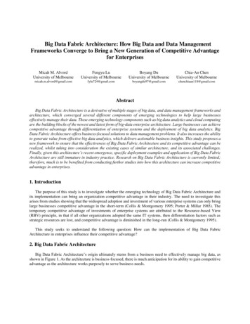
3D IC ARCHITECTURE: A NATURAL EVOLUTIONTHE CURRENT ENVIRONMENTSemiconductors continue to play an important role in society and account for an ever-increasing percentage ofcontent within electronic systems. IC Insights predicts that semiconductor content will increase from 25.4percent in 2010 to 27.8 percent in 2015. Alarm clocks, kitchen appliances, cars, office equipment, cell phones,home entertainment systems and many other work- or leisure-related products rely on semiconductors tomake work easier and play more fun.We tend to ignore many of the services semiconductors provide and instead complain (e.g., the cell phonemust be charged too frequently, the electronic fuel injection in the car wastes too much gas, the officecomputer is not fast enough, the TV picture is not clear enough, the child’s video game was too expensive).Because the consumer market is the largest for semiconductors, consumers’ needs get semiconductorvendors’ attention. IHS iSuppli reports that, today, consumer applications account for 55 percent of totalsemiconductor revenues and will reach 60 percent by 2015.The human zeal to get smarter, faster, smaller, easier to use and, above all, cheaper electronic equipmentwith longer battery life is a key driver for semiconductor innovation. This need for innovation, in regards tothe criteria listed above, has been well served by continuously shrinking the transistor feature size—thebuilding block of semiconductors.Intel’s Gordon Moore captured this trend in Moore’s Law and stated that the number of transistors in asemiconductor chip doubles every 1.5 to 2 years. The semiconductor industry followed this law successfully foralmost 50 years and met all the criteria mentioned above again and again. However, we almost forgot thatthe cost of continually shrinking ICs is bound to eventually exceed the economic benefits. In addition, ICdevelopment times are increasing very rapidly and cause companies to miss opportunities.Figure 1. Estimated Chip Design Cost, by Process Node, Worldwide, 2011Source: Gartner Report “Competitive Landscape: Application-Specific Standard ProductSemiconductors, Worldwide, 2011” (G00216498), Figure 2, Page 6.pg 3
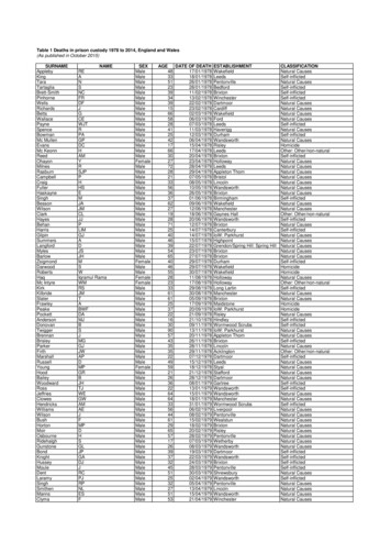
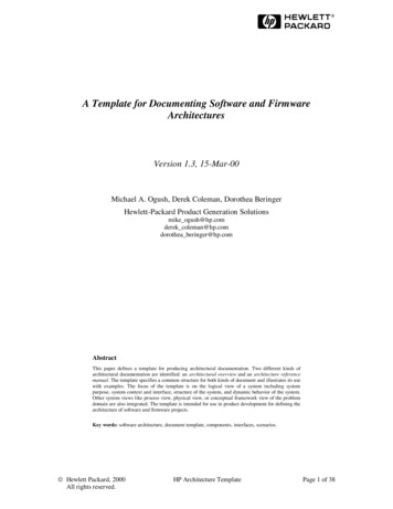
3D IC ARCHITECTURE: A NATURAL EVOLUTIONWhile engineering experts will continue to find ways to follow Moore’s Law, the economics of doing so willbecome prohibitive for many opportunities. Only very high-volume applications and the few scenarios wherecost doesn’t play a significant role will justify the up-front effort, risk, long development time and high toolingcost to design and manufacture such semiconductors.ALTERNATIVES BEYOND MOORE’S LAWThis economics challenge became obvious about a decade ago and triggered the use of the third dimension forIC design and manufacturing. Instead of continuing to pack more and more transistors on a single die,engineers developed ways to stack two or more die on top of each other. As mentioned previously, twocommon implementations are PoP (i.e., combining multiple packaged die on top of each other) and SiP (i.e.,stacking multiple bare die vertically).For multi-story buildings and skyscrapers, the sky is the limit. However, for PoP, SiP and similarconfigurations, the limit is the package height allowed in electronic equipment. High-volume applications suchas smartphones and tablets impose strict limits of typically less than 1 mm ( 1/32 of an inch). PoP and evenSiP configurations with multiple die quickly exceed this height limit. Both types also restrict the number ofconnections between stacked ICs (PoP) or die (SiP) to less than a few hundred. Graphics applications andvideo processing, both important tasks for smartphones and tablets, need much more bandwidth (equalingmore connections) between the logic die and memories to allow for high-quality images and, at the sametime, low power consumption to enable long battery life.Figure 2. A Two-Package PoP Configuration (Top Package is SiP)Source: Christine Connolly, (2009) "Miniature electronic modules for advanced health care", Sensor Review,Vol. 29 Iss: 2, pp.98 – 103. Image supplied by Microdul AG.The biggest challenge for today’s ICs with only one die in the package is to keep power dissipation withincertain limits and avoid excessive heat to assure correct functionality and long-term reliability of the IC. Whenmultiple die get stacked inside a package, the resulting increase in power dissipation is even more likely tocause excessive heat and impact IC parametrics, functionality as well as reliability.As Figure 3 demonstrates, wire bonding of several die in a stack can get quite challenging and is clearlylimited to hundreds of interconnections between die. TSV technology and micro bumps have proven toperform well with 10,000 interconnections, and even larger numbers of interconnections are planned andpossible.pg 4
3D IC ARCHITECTURE: A NATURAL EVOLUTIONFigure 3. Wire Bonding of Several Die in a StackSource: ITRSBENEFITS OF 3D IC TECHNOLOGYAgain, 3D IC is the natural evolution of our industry; it is the convergence of performance, power andportability. The economic and technical improvements in performance, power, form factor, time-to-market,cost and risk will drive the use of 3D system ICs.This new generation of three-dimensional ICs is comprised of vertically stacked, thinned die. TSVs conductpower and signals through the die stack. Micro bumps, copper-to-copper pillars and/or other means are usedto interconnect the individual die and enable very high packing density. The number of interconnects ispractically unlimited because the geometries of all these interconnections are one to two magnitudes smallerthan what is possible in PCB assemblies and PoP and SiP configurations today.Lower Power Dissipation Longer Battery LifeAs previously mentioned, reducing IC power dissipation and minimizing the resulting heat are key challengesfor IC design and manufacturing, and can be significantly reduced with 3D ICs. Input/output (I/O) power: Today’s I/O buffers need to charge and discharge package pins, andPCB traces between ICs. The relatively large I/O buffers on the sending and receiving ICsconsume typically 20 to 30 percent of an IC’s power. In 3D ICs, the required I/O power as well asthe distances signals travel are orders of magnitude reduced.Core power: As Figure 4 demonstrates, most of the core power in today’s two-dimensional circuits(2D systems-on-chip (SoCs)) is consumed by the global interconnects between circuit blocks andby the local interconnects between individual transistors. Both grow with increasing frequencies.The power consumed by global interconnects increases rapidly with the growing die sizes of 2DSoCs.3D IC advantage: Partitioning larger die into several smaller ones and stacking them verticallyreduces not only total die cost, by increasing the number of good die per wafer and reducing thenumber of metal layers needed for on-die interconnects, but also reduces interconnectcapacitance, power dissipation and delay times.pg 5
3D IC ARCHITECTURE: A NATURAL EVOLUTIONConsidering that many of the electronic systems we use every day are battery-powered, the lower powerdissipation of 3D ICs in these products will extend the time between recharging and/or allow for smallerbatteries and smaller, lighter systems. Samsung was able to reduce package size by 35 percent,power consumption by 50 percent and increase bandwidth by a factor of eight by converting a PoPconfiguration into a 3D TSV interconnected die stack.In a system implemented with multiple 2D ICs, a signal must travel through on-chip wiring, an output buffer,a big solder bump, PCB traces, an input buffer and on-chip wiring until it can finally arrive at anothertransistor. This long path consumes a lot of power and introduces significant signal delays. Further shrinkingof transistors in 2D ICs does not promise significant gains anymore because the wire delay far exceeds thetransistors’ intrinsic delays. 3D ICs shorten the distance a signal must travel and replace the high-capacitanceand high-power paths between 2D ICs with much smaller TSVs and micro bumps.Figure 4. Schematic Structure of a CMOS ChipSource: Self-made (from university scripts and scientific papers); Author: CepheidenThe cross section in Figure 4 shows how dominant the interconnect layers are compared to the tiny transistorson the bottom of the IC structure.pg 6
3D IC ARCHITECTURE: A NATURAL EVOLUTIONHigher PerformanceFigure 4 demonstrates that interconnect capacitance, and the power consumed with charging and dischargingit, limits performance within 2D SoCs. 3D ICs not only reduce these limitations, but also eliminate the need forsignals to pass through large (equals slow) I/O buffers, PCB traces and package pins to get to another ICcore.The parasitic capacitance of micro bumps and TSVs is magnitudes smaller than what signals traveling from a2D SoC to another 2D SoC or a memory chip are facing today. The respective latency and access time benefits(measured in picoseconds) contribute significantly to higher IC and system performance.For multi-core and many-core computing, as well as for graphics and video processing, the availablebandwidth (measured in megabytes per second) between central processing unit (CPU) or graphics processingunit (GPU) and memory dictates picture quality. 2D SoC solutions require very high pin-count (equalsexpensive) packages or multiple ICs to overcome the so-called “memory wall” (the bandwidth limitationswhen accessing memory). 3D ICs with a memory cube stacked on top of (or below) the CPU/GPU can costeffectively offer already 10,000 interconnects today and enable bandwidths essential for many futureapplications.Smaller Form FactorDuring the time this report was written, Apple was expected to announce the iPhone 5—a sleeker, thinner,feature-rich successor of the popular iPhone 4. However, to date, they have “only” announced the iPhone 4Swith the same form factor as the “old” iPhone 4. The media, consumers and investors were disappointed andconcerned that Apple under new management may not continue its innovation leadership. Apple’s phenomenalsuccess with products such as the iPod, iPhone and iPad has made it the world’s largest customer forsemiconductors. By the time you read this paragraph, details about their plans and activities to utilize 3Dtechnology to further slim down their volume runners may be public.Form factor is not only important for mobile Internet devices (MIDs), but is also essential for many otherapplications, for example, in the medical field. Smaller hearing aids, heart monitors, visual aids and otherdevices with sensors and intelligent electronics will aid humans in interacting with their environment. Forexample, combined with microelectromechanical systems (MEMS) in the die stack, very small and intelligentblood sugar monitors and insulin pumps can be created with 3D ICs.Shorter Time-to-MarketThe consumer market is now the largest user of semiconductors. While unit volumes in this market can reachhundreds of millions, the revenues and profits achievable in the first few months can be significant too. Forexample, Apple’s iPad crossed the one million unit mark and achieved more than 600 million in revenueswithin the first 100 days on the market. VCRs, DVD players, cell phones and other consumer products haveexperienced similar ramps and demonstrated the power and profit potential of being first to market.Development times for high-complexity 2D SoCs are in the range of one to two years and often requireredesigns that delay time-to-market even further. Most have very high software content. Software andhardware interaction can only be exhaustively tested on the fully functioning hardware. These system-leveltests can add additional months, even quarters, to the release date.pg 7
3D IC ARCHITECTURE: A NATURAL EVOLUTIONDesigning a new 2D SoC is error-prone and often requires redesign efforts that can delay market entrysignificantly. 3D IC technology offers system and IC designers the capability to partition a system into smallerdie and create reusable (die-level) building blocks. A redesign of such a small die, if mandated by a designerror or changing market requirements, takes much less time and effort than a redesign of a large 2D SoC.Software testing can also start earlier because it’s easier to emulate the one building block that is undergoinga redesign.Lower Development, Tooling and Unit CostsMoore’s Law has always introduced new IC design challenges and higher up-front costs. However, the unitcost reductions, power savings, performance enhancements and other benefits have always more thancompensated a company for choosing the shrink path—until recently. The transition to the latest processgenerations shows further diminishing returns in regards to performance enhancements, power reduction andunit cost savings. Because IC design efforts and up-front costs increase exponentially, only very high-volumedesigns can still justify continued shrinking. In contrast, 3D IC technology offers several ways to reduceupfront and unit costs: Partitioning very large 2D SoCs into smaller die increases not only the number of die per wafer,but also increases the likely yield. Both lead to significantly lower die cost.Smaller die are likely to require fewer metal layers for on-die interconnects. Lower waferprocessing cost, shorter processing times and higher yields are the result.3D ICs enable designers to choose the most suitable process technologies for implementing logic,memory, analog/radio frequency (RF) functions and MEMS. This flexibility not only assures thebest possible technical characteristics, but also offers designers the ability to choose the mosteconomical process technology to lower cost. While foundries have developed remarkably flexibleprocesses to meet diverging requirements in 2D SoCs, significant trade-offs are needed whenimplementing logic, memory, analog/RF circuits and MEMS in such universal processes.3D ICs do not force designers to utilize smaller and smaller feature sizes to pack all the neededfunctionality onto one die. They can utilize proven die-level intellectual property (IP) in basicallyany feature size. With smaller feature sizes, design and verification efforts increase, and maskcost almost doubles with every process generation. In addition, smaller feature sizes result inincreasing process variability. This not only narrows design margins but also makes productionyield—and with it unit cost—less predictable.Die-Level Modularity Reduces RiskModularity not only reduces time-to-market, but also reduces the risk of failure. Similar to combining fullypackaged ICs on a PCB, designers can rely on proven building blocks, now in die form, to integrate subsystems or entire systems in a 3D IC. However, how to connect power, control and data lines with other die inthe stack needs to be agreed upon ahead of time. If the die in a stack come from the same source, suchagreements are relatively easy to reach. If die from multiple sources are needed, industry-wide standardsneed to be established to fully utilize the benefits of proven IP in die form. The report section “EcosystemCollaboration and Design and Manufacturing Standards” addresses these ecosystem considerations andoutlines the ongoing efforts to agree upon design and manufacturing standards. Standards will enableindustry-wide cooperation, efficient IP reuse, and lower development time, risk and cost.BENEFITS DEMONSTRATED BY EARLY ADOPTERS3D ICs vs. Interp
Jun 03, 2012 · The idea of 3D is not new. Two widely used technologies—system-in-package (SiP) and package-on-package (PoP)—have already demonstrated the benefits of using the third dimension in IC design. Both have enabled designers to pack more functionality at higher