Transcription
PTER 3PRIMARY TREATMENTLearning ObjectivesThis chapter covers the major concepts associated with primary treatment. By the end ofthis chapter, a student should be able to: Define the objective of the primary treatment process; Distinguish between primary sedimentation tanks and secondary clarifiers; Identify the basic principle underlying the primary treatment process; Describe the components of primary sedimentation tanks including inlet andoutlet structures; Explain the main considerations for sludge and scum removal and disposal; List the factors that affect primary sedimentation tank efficiency; Describe the key elements of process control and testing as these relate to theoperation of the primary sedimentation tank; Outline the key troubleshooting and maintenance concerns related to primarytreatment; and Identify the specific safety concerns associated with the primary sedimentationprocess.IntroductionSewers are designed to provide a wastewater velocity of at least 0.6 m/s (2.0 ft/sec).Because the wastewater in collection systems moves relatively fast, the solids stay insuspension. When wastewater enters a treatment plant, it first passes through a bar screenwhich removes the larger solids, or through a grinder or comminutor, which reduces the size ofthe larger particles. After screening or grinding, the wastewater flows to a grit chamber whereheavier undesirable solids are removed. The velocity of the wastewater to this point has keptthese solids in suspension. In the grit tank, the speed of the wastewater is reduced to about 0.3m/s (1.0 ft/sec). This decreased velocity allows the inorganic solids or grit to settle out, but stillallows the lighter organic solids to remain in suspension. If the speed of the wastewater isreduced to below 0.3 m/s (1.0 ft/sec), heavier materials will settle and lighter materials will rise tothe surface. This solids-liquids separation using a reduced velocity and a force such as gravity isknown as sedimentation. This is what occurs in the primary treatment process at a wastewatertreatment plant.Both organic and inorganic solids are present in wastewater, and both can be eithersuspended or dissolved. Settleable solids are the portion of suspended solids that readily settle ina primary sedimentation tank when the wastewater velocity is reduced to a fraction of a meter orfoot per second. Typically, 90 – 95% of settleable solids settle out during primary treatment(Figure 3.1). Colloidal solids, which are finely divided solids, are too fine to settle within the usualdetention times of a primary sedimentation tank. Colloidal solids readily pass through the primarytreatment process and are treated in the secondary treatment process. Primary sedimentationtanks reduce the wastewater velocity to less than 0.3 m/s (1.0 ft/sec) and allow these settleablesolids to separate from the waste stream. This process also removes a percentage of suspendedsolids as well as Biochemical Oxygen Demand (BOD) that are associated with these solids.Typical removal efficiencies that can be achieved in primary treatment are as follows in Table 3.1.Table 3.1 - Removal Efficiencies of Primary TreatmentPrimary Treatment3-1
1ParameterSettleable SolidsSuspended SolidsBODRemoval Efficiency90 – 95 %50 – 65 %20 – 35 e 3.1 Schematic of Primary Treatment ProcessBetter primary treatment efficiencies can be expected with fresh wastewater than withwastewater that has turned septic because of long travel times in the collection system. Septicwastewater contains anaerobic bacteria that produce gas. This gas, in turn, causes the solids tobe buoyed as nitrogen bubbles rise.Primary settling tanks can be rectangular, square, or round. The shape of the tank doesnot affect its removal efficiencies. As you can see below, a primary settling tank is usuallydesigned with the following parameters:Primary Settling: Detention time of 1 - 2 hrs; Surface overflow rate of 32 600 – 48 900 L/m2·d (800 – 1200 gpd/ft2) for averageflow; 81 500 –122 000 L/m2·d (2000 – 3000 gpd/ft2) for peak flow; and Weir overflow rate, 124 000 – 496 000 L/m·d (10 000 – 40 000 gpd/ft)Primary Settling with Waste Activated Sludge Return (Cosettling): Detention time of 1 – 2 hrs;3-2Operations Training/Wastewater Treatment
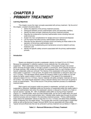
556 Surface overflow rate of 24 420 – 32 560 L/m2·d (600 – 800 gpd/ft2) for averageflow;48 840 – 69 190 L/m2·d (1200 – 1700 gpd/ft2) for peak flow; andWeir overflow rate, 124 000 – 496 000 L/m·d (10 000 – 40 000 gpd/ft)These design parameters may change slightly based on site-specific conditions. We willexamine these parameters in greater detail later in the chapter.Primary and secondary clarifiers essentially share the same primary function: to removesolids from water using sedimentation. They also have similar configurations and designs.However, based on the design parameters listed above, we can examine some fundamentaldifferences between primary and secondary clarifiers. The average surface overflow rate for asecondary clarifier ranges from 24 000 to 33 000 L/m2·d (600 to 800 gpd/ft2) and a wier overflowrate of 125 000 to 250 000 L/m·d (10 000 to 20 000 gpd/ft). These numbers are lower than thoseof a primary settling tank. What these numbers translate to is that a secondary tank is typicallylarger in diameter and surface area than a primary tank. However the depth of a primary tank isusually somewhat greater than that of a secondary tank. This means secondary tanks are largerand more spread out. The reason for this is that secondary tanks typically remove solids that aremuch lighter in comparison to those removed by a primary tank. Therefore, a longer detentiontime is needed. This “spread out” design allows for a proper volume of wastewater to passthrough with adequate detention time and also reduces the depth to which the solids have tosettle.Tank Configurations and ComponentsDifferent names can be used to refer to primary treatment tanks. They are alternatelycalled clarifiers, sedimentation basins, or settling tanks. In this chapter, we will refer to primarytreatment units as primary settling tanks or primary tanks. Despite its location on a treatmentplant or its shape, the purpose of all settling tanks is the same - to reduce wastewater velocityand mixing so that settling and flotation will occur. It is important to realize that only the settleablesolids are removed in the settling tank. Lighter solid material remains in the wastewater or floatsto the surface and must be removed through different means. Primary tanks are typically locatedright after preliminary treatment. If the primary tank is not removing enough settleable solids fromthe wastewater, increased oxygen demand can result and inhibit later biological processes.However, if too many settleable solids are removed, there may not be enough organic matter forthe biological system to perform properly.When wastewater is placed in a cone (such as an Imhoff cone) and allowed to sit,settleable solids settle to the bottom, and lighter floatable solids rise to the top. This is essentiallythe same thing that happens in a primary settling tank (sedimentation). The settling process relieson gravity to separate the solid material from the liquid. Settling tanks are simply large tanksdesigned to distribute flow uniformly throughout the tank. This uniform distribution helps reducethe wastewater velocity and amount of mixing equally throughout the tank. Under theseconditions, solid materials, which were carried in suspension by the waste flow, will settle to thebottom as sludge or float to the surface as scum. Colloidal, or finely divided, solids that will notsettle and dissolved solids will remain in the liquid and be carried on for further processing.Figures 3.2 and 3.3 show what happens in a rectangular settling tank. Flow entering from the leftis evenly distributed throughout the tank. As the wastewater flows through the tank, heavier solidssettle to the bottom where they are removed (Figure 3.2). At the same time, lighter material orscum rises to the top, where it too is removed (Figure 3.3). The same type of action occurs in acircular settling tank, except that the wastewater enters the tank at the middle and flows outtoward the perimeter of the tank.Primary Treatment3-3
1234567891011121314Figure 3.2 – Primary Settling Process – Solids SettlingFigure 3.3 – Scum Collection for a Rectangular ClarifierIn Table 3.2 we see the basic design dimensions of both rectangular and circular primarysettling tanks. Note that for both designs, depth is typically the same. There are several keyelements to the primary settling process. Let us now take a closer look at these individualelements.3-4Operations Training/Wastewater Treatment
031Table 3.2 Dimensions and Parameters for Rectangular and Circular Primary SettlingTanksInletThe settling tank inlet slows down the velocity of wastewater entering the tank anddistributes the flow across the tank. If more than one settling tank is being used, a splitter boxplaced before the inlet divides the flow evenly into each tank. Settling tanks can use a variety ofinlet structures.Figure 3.4 illustrates a spaced port opening arrangement for a rectangular primary tank.The diagram also shows the action of a spaced port opening inlet structure. This inlet structurereduces the velocity of wastewater entering the tank and distributes the flow across the tank. Theother main type of rectangular clarifier inlet structure includes an elbow that directs the influentflow below the surface and down, rather than straight across. Often, a "tee" structure is used sothat the pipe can be easily cleaned. If the "tee" structure is omitted, a baffle is needed near theinlet to help spread the flow of wastewater evenly throughout the tank.Figure 3.4 Inlet Flow Distribution for a Rectangular Primary TankThe usual inlet arrangement in a circular settling tank is a vertical pipe in the center of thetank with the influent well at the top (Figure 3.5). Another design alternative is the side-entryfeed, with the inlet pipe coming from the sidewall of the tank to the center influent well. Whethercenter or side-entry feed is used, this influent well typically has a diameter that is 15 to 20% of thetank’s diameter. A circular baffle around this inlet forces the wastewater to flow toward thebottom of the tank around the pipe. As we will discuss shortly, you may also find baffling near theoutlet structures of circular tanks to help with flow distribution. In all settling tanks, the purpose ofthe inlet structure is to reduce the velocity of the wastewater entering the tank and distribute theflow evenly across the tank. This even distribution is important for proper settling.Primary Treatment3-5
1234567891011121314151617181920Figure 3.5 Inlet Flow Distribution for a Circular Primary TankFlow DistributionThere can be serious consequences if the inlet does not distribute the flow evenlythroughout the tank. If the speed of the wastewater is greater in some areas of the tank thanothers, a condition called "short-circuiting" (Figure 3.6) can occur. In places where the wastewateris moving faster, particles that are suspended in the wastewater may not have a chance to settleout. They will be held in suspension and will pass through to the discharge end of the tank. It isdesirable to maintain even flow distribution to prevent short-circuiting in the settling tank. A baffleis commonly used to reduce short-circuiting. The flow of wastewater hits the baffle and dispersesevenly, ensuring a good flow in the tank. In the circular settling tank, the wall of the influent wellacts as the baffle. Finally, the overflow weirs must be perfectly level to ensure good flowdistribution and help prevent short-circuiting.Figure 3.6 Short-Circuiting in a Primary Tank3-6Operations Training/Wastewater Treatment
03132333435363738394041424344454647484950Also proper flow distribution and baffling is essential to help deal with the formation ofdensity currents (Figure 3.7). Density currents are formed by the improper inlet distribution ofinfluent solids. These solids are denser than the clarifier contents and immediately begin to movedown towards the sludge blanket. However, due to improper inlet distribution it retains a highervelocity than the rest of the contents. This newly formed current will simply deflect off of thesludge blanket and use its momentum to carry itself to the clarifier outlet structure, often carryingsludge from the blanket with it. Baffles may be installed near the outlet weirs to help prevent thissolids loss. These baffles will be discussed further as we discuss primary tank outlet structures.Figure 3.7 Formation of a Density Current in a Circular Primary TankSettlingIf the flow is properly distributed, then the effective separation of settleable solids fromwastewater in the settling tank can occur. As described earlier, the best way to obtain thisseparation is to allow the liquid to remain very still for several hours. This allows most solids in theliquid to settle to the bottom of the settling tank, where they are removed for further processing.Any solids that float to the surface are removed by scum collection devices and furtherprocessed. Most organic settleable solids weigh only slightly more than water. So they settle veryslowly. Settling tanks are designed with this fact in mind. The velocity of the liquid in the settlingtank is slowed down to a fraction, approximately 0.001 m/s (0.003 ft/sec), of its influent velocity ascompared to about 0.3 m/s (1.0 ft/sec) in the grit chamber, and at least 0.6 m/s (2.0 ft/sec) in thesewer. As the wastewater moves across the settling tank, heavier suspended solids have enoughtime to settle to the bottom of the tank. Some of the lighter suspended solids will also settle, butothers, are so light, that they pass completely through the tank. Again, for proper settling to occurin the settling tank, the liquid must move very slowly. The wastewater must stay in the settlingtank long enough for solid particles to settle. If the tank is too small for the volume of flow enteringit, too many particles will exit with the tank effluent.Detention TimeThe length of time that wastewater stays in the settling tank is called the detention time.Approximately 1– 2 hours of detention time are needed in the primary settling tank as was notedat the beginning of this chapter. The exact time depends on many factors such as the influentflow rate and the removal requirements needed by downstream processes. If the detention time istoo long, solids may become septic and float to the surface. High suspended solids levels in theprimary effluent and subsequent odors may result. A secondary clarifier requires a longerdetention time than a primary settling tank because the light and fluffy activated sludge particlesdo not settle as easily as the heavier solids removed in a primary tank. How efficiently the settlingtank removes settleable solids depends on how slow the liquid moves (influent velocity) and onthe detention time. Let us look at an example of calculating detention time.Volume of primary settling tankFlow rateGiven the following dimensions and flow rate for a circular primary settling tank, we willcalculate the detention time:Tank diameter 7 mTank depth 4 mFlow rate to tank 1 892 400 L/dDetention time First, calculate the surface area of the tank in m2:25152532 Diameter , m 7m 22Surface area, m2 π π π(3.5 m) 38.465 m22 Next, calculate the volume of the tank in liters:Primary Treatment3-7
1Volume of settling tank, L (Surface area, m2)(Depth, m)(1000 L1m 3)234567891011121314151617181920Volume of settling tank, L (38.465 m2)(4 m)(2223241m 3) 153 860 LThen, convert the flow rate to L/h:(1 892 400 L/d)(1d /24 h) 78 850 L/hNow, calculate the detention time:Detention time, h 153 860 L 1.95 h, round up to 2 hoursL78 850hLet us now perform the same calculation using English units.Given the following dimensions and flow rate for a circular primary settling tank, we willcalculate the detention time:Tank diameter 26 ftTank depth 10 ftFlow rate to tank 476 315 gpdFirst, calculate the surface area of the tank in ft2:2211000 L2 Diameter , ft 26 ft 22Surface area, ft2 π π π(13 ft) 530.66 ft2 2 Next, calculate the volume of the tank in gallons:Volume of settling tank, gal (Surface area, ft2)(Depth, ft)(7.48 gal1 ft 3)25262728293031323334353637383940414243Volume of settling tank, gal (530.66 ft2)(10 ft) (7.48 gal1 ft 3) 39 693 galThen, convert the flow rate to gal/hr:(476 315 gal/d)(1d /24 h) 19 846 gal/hrNow, calculate the detention time:Detention time, hr 39 693 gal 2 hrga l19 846hrOverflow RateThe surface overflow rate is a measure of how rapidly wastewater moves through thesettling tank. When we talk about surface overflow rate, we are referring to the number of gallonsgoing through the settling tank each day for each square foot of surface area in the tank, or thenumber of liters for each square meter per day. In other words, we are looking at the hydraulicwastewater load for each square meter, or square foot, of surface area in the settling tank eachday. This diagram (Figure 3.8) might help you understand what we mean by the surface overflowrate. Imagine placing a net on the surface of the settling tank liquid. Each space in this net equals3-8Operations Training/Wastewater Treatment
123456789101112131415161718192021222324one square meter, or one square foot. Focus on just one of these squares. Surface overflow rateis the number of liters flowing through one square meter each day, or the number of gallonsflowing through this one square foot each day.Figure 3.8 Representation of Surface Overflow RateAs we stated earlier in this chapter, for proper settling, the suggested surface overflowrate for primary tanks varies from 32 600 – 122 000 L/m2·d (800 – 3000 gpd/ft2), depending onthe nature of the solids and the treatment required. Let us look at an example calculation fordetermining the surface overflow rate. The surface overflow rate is defined as the loading acrossthe surface of your primary tank defined as follows:Surface overflow rate For our sample calculation, we will use the same dimensions and flow rates as ourprevious example.Given:Tank diameter 7 mFlow rate to tank 1 892 400 L/dFirst, calculate the surface area of the tank in m2:2252627Flow rate to the tankSurface area of the tank2 Diameter , m 7m 22Surface area, m2 π π π(3.5 m) 38.485 m22 Next, simply divide the flow rate by the surface area:1 892 40028Surface overflow rate, L/m2·d 38.485 mLd 49 173 L/m2·d round up to 49 200 L/m2·d2Primary Treatment3-9
12345678Let us now perform the same calculation using English units.Given:Tank diameter 26 ftFlow rate to tank 476 315 gpdFirst, calculate the surface area of the tank in ft2:291011122 Diameter , ft 26 ft 22Surface area, ft2 π π π(13 ft) 530.93 ft22 Next, simply divide the flow rate by the surface area:gald 897 gpd/ft2 round up to 900 gpd/ft2Surface overflow rate, gpd/ft2 530.93 ft 2476 6373839404142434445464748EfficiencyMany factors can affect the efficiency of a settling tank. One factor is the type of solids inthe system. This is especially important if a large amount of industrial waste is present. Anotherfactor is the age of the wastewater when it reaches the plant. Older wastewater becomes stale orseptic, and solids will not settle properly because gas bubbles form and cause them to float.Settling tank efficiency also depends on the rate of wastewater flow, as we have discussed.When flow rates are high, detention times decrease and settling is less efficient. Anotherimportant factor is the cleanliness and mechanical condition of the settling tank; poorhousekeeping or broken equipment can reduce settling efficiency. At this point you should askyourself how well your primary settling tank is performing during proper operation. In the primarysettling tank, about 50 – 65% of the suspended solids will be removed. If we look at just thesettleable solids, close to 100% should be removed. Because some of the suspended solids areorganic, BOD will also decrease by approximately 20 – 35%. The best way to determine theefficiency of a primary tank is to examine both the tank influent and effluent characteristics, suchas BOD and suspended solids. Using these numbers you can determine the removal efficiencyof your primary settling tank. Let us look at a brief example. Removal efficiency is calculated asfollows:Removal efficiency, % Parameter In - Parameter Outx 100%Parameter InWe are given the following data:Primary Influent BOD 180 mg/LPrimary Effluent BOD 130 mg/LNow we can calculate our removal efficiency:180 mg/L - 130 mg/Lx 100% 27.8% round up to 28%180 mg/LBased on our design parameters, this an acceptable removal efficiency for our primarysettling tank.Removal efficiency, % OutletSo far, we have discussed the settling tank inlet and the clarification that occurs in thesettling tank. Now let us look at the clarifier outlets. Wastewater leaves the settling tank by flowingover weirs and into effluent troughs or launders, as shown in Figure 3.9. The purpose of a weir isto allow a thin film of the clearest water to overflow the tank. A high velocity near the weir can pullsettling solids into the effluent. The length of the weir in the settling tank compared to the flow is3-10Operations Training/Wastewater Treatment
12345678910important in preventing high velocities. A baffle at the outlet end of a rectangular tank or aroundthe edge of a circular tank helps prevent short-circuiting and floating solids from leaving the tank.As we mentioned earlier, baffles are also used near the outlet weirs (Figure 3.10) to help dealwith density currents. Two of the more common types used are the Crosby and Stamfordperipheral baffles.Figure 3.9 Effluent Weirs and Launder for a Primary Settling TankPrimary Treatment3-11
123456789101112131415161718192021222324Figure 3.10 Peripheral Baffles for a Primary Settling TankOperators should make sure that flow from settling tanks is uniformly distributed whenoverflowing the weir. Most tank weirs can be adjusted and made level so that effluent flow isuniformly distributed. Assuming that flow over the weir is uniformly distributed, one way todetermine whether you have sufficient weir length is to calculate the daily flow over each meter,or each foot, of weir. This measurement is called the weir overflow rate. The weir overflow rateequals the number of liters per meter of weir per day, or the number of gallons of wastewater thatflows over one foot of weir per day.Weir overflow rate Wastewater flow, L/d (gpd)Length of weir, m (ft)Secondary clarifiers with higher effluent quality requirements generally need lower weir overflowrates than primary tanks. Let us perform a sample calculation for the weir overflow rate using thesame parameters as our other examples including the length of the weir.Given:Tank diameter 7 mLength of weir 22 mFlow rate to tank 1 892 400 L/dWeir overflow rate, L/m·d Wastewater flow, L/dLength of weir, m25262728 1 892 400 L/d 86 018.18 L/m·d, round up to 86 020 L/m·d22 mLet us now perform the same calculation in English units.3-12Operations Training/Wastewater Treatment
123456Given:Tank diameter 26 ftLength of weir 82 ftFlow rate to tank 476 315 gpdWeir overflow rate, gpd/ft Wastewater flow, gpdLength of weir, ft7891011121314151617181920212223242526272829 476 315 gpd 5808.72 gpd/ft, round up to 5810 gpd/ft82 ftSludge RemovalWe have talked about the inlet, clarification, and outlet. Another important step in thesettling process is sludge removal. Since the main purpose of a primary settling tank is to allowsolids to settle out of the wastewater, we cannot just leave them in the tank. Figure 3.11 is arectangular tank cross section including the solids removal equipment. The main components arethe flights, drag chains, head shaft and idler shafts. The wooden or fiberglass beams, commonlycalled flights, are attached to drag chains, which are connected to form a closed loop. The headshaft is rotated by the drive chain. This rotation causes the drag chains and flights to movethrough the settling tank. Solids that settle to the bottom of the settling tank are scraped to ahopper or trough. Most small rectangular tanks have two hoppers. Solids collected in thesehoppers must be removed. Larger settling tanks usually have a trough running the entire width ofthe tank. In this type of system, scrapers are used to move the solids to one end of the trough forremoval. This is called a cross-collector. In this circular settling tank (Figure 3.12), scrapers,called plows, move solids into a hopper at the center of the tank. These plows are driven by amotor mounted above the feed well structure. In both circular and rectangular tanks, solids aremoved very slowly so that they are not mixed and suspended in the wastewater again.Figure 3.11 Sludge Removal Components for a Rectangular Primary TankPrimary Treatment3-13
031Figure 3.12 Sludge Removal Components for a Circular Primary TankAfter settled sludge has been moved to the sludge hopper, it still has to be removedcompletely from the tank. The method used to remove this sludge will affect the sludgestabilization process. For example, if your plant uses anaerobic digesters, the smaller the volumeof sludge that you pump into the digester, the fewer digester problems you will have. Becausemost plants' digesters are built to handle only the minimum volume necessary for continuoustreatment, it is important to pump sludge wisely. All sludge must be removed from the primarytanks, so it should be concentrated into the least possible volume. This means pumping thesludge with as little water as possible. The solids collected in the primary tank hopper arepumped to the sludge stabilization process or solids handling process. What happens to theprimary sludge will depend on the plant design. Solids handling systems vary from plant to plantand include the use of aerobic digesters, anaerobic digesters, centrifuges, belt presses, and othersolids handling processes.As previously discussed, the amount of sludge pumped from the primary tanks is animportant factor, and the type of equipment used to remove the sludge varies. Typically,treatment plants use piston pumps, diaphragm pumps, or progressing cavity pumps to removesludge from primary tanks (Figure 3.13). Some plants use centrifugal-type pumps. However, thecapacity of centrifugal pumps can be affected by the solids concentration and sludgecharacteristics. Many primary sludge-pumping systems have variable pump speed capability,such as manually adjusted belts, variable-frequency drives, or adjustable-gear units. Adjustablepump outputs reduce the chance of coning in the sludge hopper and subsequent pumping ofwater only. Also, adjusting the pump rates can benefit the solids-handling facilities. Primarysludge-pumping systems typically have start and stop timers. Some plants use timers to start thepumping system and density meters to stop the pumps. Many plants today use programmablecomputers on their sludge-withdrawal systems, while others use manual timing operations.3-14Operations Training/Wastewater Treatment
1234567891011121314151617181920Figure 3.13 Primary Sludge Pumps – Piston PumpScum RemovalThe final main step in the primary clarification process is scum (skimmings) removal.Scum is removed from all primary tanks. In rectangular tanks, the flights that scrape the bottomsludge in one direction also move across the surface of the liquid in the opposite direction,pushing scum that has floated to the surface to a trough at the end of the tank. As shown inFigure 3.14, the scum trough lies along the edge of the tank. The trough is actually a long pipewith an open slot cut across the top. To remove scum from the tank, this pipe, the scum trough,rotates to allow the scum to enter the trough through the open slot. Scum is removed from thetank by turning the slotted pipe toward the scum, so that the scum is carried into the pipe by thein rushing water. This pipe or scum trough is connected to a scum pit where the scum is stored.The operator must take care to skim the maximum amount of scum while collecting the minimumof water. In circular tanks, a surface blade pushes the scum to a hopper located at the edge ofthe tank, as shown in Figure 3.15. The hopper drains through a pipe into the scum pit. Primarytanks will also often incorporate scum baffles to prevent scum from making their way to theeffluent weirs. These baffles can best be described as a vertical extension of the sidewalls.Primary Treatment3-15
12345Figure 3.14 Scum Removal for a Rectangular Primary Tank6789Figure 3.15 Scum Removal for a Circular Primary Tank3-16Operations Training/Wastewater Treatment
556Because of the kinds of material collected in a scum pit, it is strongly recommended thatno scum be pumped into the anaerobic digester. However, in many plants, the anaerobic digesteris the only place the scum can be sent. Scum layers can cause serious problems in digesters withpoor or no mixing. Scum from the scum pit should be dewatered or concentrated and disposed ofin an approved manner such as landfilling or incineration.Chemical AdditionIt may be necessary, ba
3-4 Operations Training/Wastewater Treatment 1 2 3 Figure 3.2 - Primary Settling Process - Solids Settling 4