Transcription
Ontology-driven Conceptual Designof ETL Processes using Graph Transformations?Dimitrios Skoutas1,2 , Alkis Simitsis3 , and Timos Sellis212National Technical University of Athens,Athens, Greecedskoutas@dblab.ece.ntua.grInstitute for the Management of Information Systems (R.C. “Athena”)Athens, Greecetimos@imis.athena-innovation.gr3HP Labs and Stanford UniversityPalo Alto, California, USAalkis@hp.comAbstract. One of the main tasks during the early steps of a data warehouse project is the identification of the appropriate transformations andthe specification of inter-schema mappings from the source to the target data stores. This is a challenging task, requiring firstly the semanticand secondly the structural reconciliation of the information provided bythe available sources. This task is a part of the Extract-Transform-Load(ETL) process, which is responsible for the population of the data warehouse. In this paper, we propose a customizable and extensible ontologydriven approach for the conceptual design of ETL processes. A graphbased representation is used as a conceptual model for the source andtarget data stores. We then present a method for devising flows of ETLoperations by means of graph transformations. In particular, the operations comprising the ETL process are derived through graph transformation rules, the choice and applicability of which are determined bythe semantics of the data with respect to an attached domain ontology. Finally, we present our experimental findings that demonstrate theapplicability of our approach.1IntroductionSuccessful planning and decision making in large enterprises requires the abilityof efficiently processing and analyzing the organization’s informational assets,?This is the author’s version of the work. It is posted here for your personal use. Not forredistribution. The definitive version was published in JoDS XIII, 2009 and it shouldbe cited as: “D. Skoutas, A. Simitsis, T.K. Sellis. Ontology-driven Conceptual Designof ETL Processes using Graph Transformations. Springer Journal on Data Semantics(JoDS), Special issue on “Semantic Data Warehouses” (JoDS XIII), LNCS 5530, pp.119-145, 2009.” The original publication is available at www.springerlink.com.
2D. Skoutas, A. Simitsis, and T. Sellissuch as data regarding products, sales, customers, and so on. Such data are typically distributed in several heterogeneous sources, ranging from legacy systemsand spreadsheets to relational databases, XML documents and Web pages, andare stored under different structures and formats. For this purpose, as well asfor performance issues, data warehouses are employed to integrate the operational data and provide an appropriate infrastructure for querying, reporting,mining, and for other advanced analysis techniques. On the other hand, the explosion of the information available in Web repositories, further accelerated bythe new trends and technologies referred to as Web 2.0 and combined with theever increasing information needs, necessitates that modern applications oftendraw from multiple, heterogeneous data sources to provide added value servicesto the end users. Such environments raise new challenges for the problem of dataintegration, since naming conventions or custom-defined metadata, which maybe sufficient for integration within a single organization, are of little use whenintegrating inter-organization information sources or Web data sources.The key challenge in all such situations is how to reconcile, both semanticallyand structurally, the data between the source and target specifications. Traditionally, the integration of the operational data into the central data warehouseis performed by specialized processes, known as Extract-Transform-Load (ETL)processes. The ETL processes are responsible for the extraction of data from distributed and heterogeneous operational data sources, their appropriate cleansingand transformation, and finally, their loading into the target data warehouse. Ingeneral, the ETL processes constitute a costly –both in time and resources– andcomplex part of the data warehouse design.As a motivating example consider the following real-world case adapted froma project of the Greek public sector. The goal of that project was the modernization of the personnel management system and its transition to a modern datawarehouse environment. The operational data were stored in a combination of1152 tables and flat files. The project resulted in a set of ETL processes consisting totally of more than 500 scripts in a procedural language, where each oneof those contained more than one transformation performing a single operation.The whole process of (a) identifying the relevant and useful source tables out ofthe 1152 tables (a flat file can be viewed as an external table), (b) determiningthe inter-attribute mappings and the appropriate transformations needed, and(c) creating the ETL workflow (in a conceptual level) took approximately 7.5man-months (3 designers 2.5 months.) The basic setback in the whole processwas the vastness of the schema and the lack of supporting documents and systemdescriptions for the original implementation.Urged from this scenario and the problems that occurred during that project,we envision a novel approach that would facilitate the early stages of a data warehouse project. In a previous work, we have proposed an easy to use, yet powerful,visual language to represent this task [1]. However, in that work and in othersimilar works too [2, 3, 1] towards the conceptual design of the backstage of adata warehouse architecture (see Section 6), the design was performed manuallyby the designer. The same holds for the plethora of the commercial solutions
3currently existing in the market, such as IBM’s Data Warehouse Manager [4],Informatica’s PowerCenter [5], Microsoft’s Data Transformation Services [6], andOracle’s Warehouse Builder [7]. All these approaches, at the conceptual level,focus on the graphical design and representation of the ETL process, whereasthe identification of the required mappings and transformations needs to be donemanually.The lack of precise metadata hinders the automation of this task. The required information regarding the semantics of the data sources, as well as theconstraints and requirements of the data warehouse application, tends to bemissing. Usually, such information is incomplete or even inconsistent, often beinghard-coded within the schemata of the sources or provided in natural languageformat (e.g., after oral communication with the involved parties, including bothbusiness managers and administrators/designers of the enterprise data warehouse) [8]. Consequently, the first stage of designing an ETL process involvesgathering the available knowledge and requirements regarding the involved datastores. Given that ETL processes are often quite complex, and that significantoperational problems can occur with improperly designed ETL systems, following a formal approach at this stage can allow a high degree of automation ofthe ETL design. Such an automation can reduce the effort required for the specification of the ETL process, as well as the errors introduced by the manualprocess. Thus, in the context of a data warehouse application, and in particularof the ETL process design phase, an ontology, which constitutes a formal andexplicit specification of a shared conceptualization [9], can play a key role inestablishing a common conceptual agreement and in guiding the extraction andtransformation of the data from the sources to the target.We build on top of this idea, and more specifically, we envision a methodfor the task of ETL design that comprises two main phases. First, we consideran ontology that captures the knowledge and the requirements regarding thedomain at hand, and it is used to semantically annotate the data stores. Theontology may already exist, since in many real world applications the domainof the ETL environment is the same; e.g., enterprise or medical data. In suchcase, the ontology can be re-used or adapted appropriately. (A similar discussionon the applicability of this claim can be found in the experimental section.) Ifsuch ontology does not exist, then during the first phase of the design, a newontology should be created. Clearly, the details of this phase largely dependon the particular needs and characteristics of each project. For example, theremay exist different ways and sources to gather requirements, different methods tocreate an ontology, annotations may be specified manually or semi-automatically,and so on. In this work, we focus on the second phase of the design. Having theontology available, we investigate how the ontology and the annotations can beused to drive, in a semi-automatic manner, the specification of the ETL process.A first attempt towards this direction has been recently presented [10]. Inthis paper, we build upon the idea of using an ontology for the conceptual designof ETL processes, and, more specifically, we elaborate on that by proposing aformal way for deriving a conceptual ETL design, based on the well-established
4D. Skoutas, A. Simitsis, and T. Sellisgraph transformation theory. We exploit the graph-based nature of the datastore schemata and of the ETL processes to provide an appropriate formulation of the problem, and we present a customizable and extensible set of graphtransformation rules that drive the construction of the ETL process.Notice that the burden of using an ontology is reduced mainly to annotatingthe source and target schemata with it. Several approaches toward the facilitation of the automatic schema matching have already been proposed [11, 12].Nevertheless, we argue that even if the designer has to do the whole task manually, still, it will be easier to map individual attributes (one each time) to adomain ontology rather than try to fill in the puzzle having all the pieces aroundat the same time. Additionally, the existence of an ontology that carries themapping of the source and target tables can be used in other applications aswell. We mention two prominent examples: (a) the use of such an ontology toproduce reports in natural language [13, 14]; and (b) such an ontology can beused as a convenient means to data warehousing web data, as an individual mayeasily plug-in his/her data source into the ontology and then, the ETL can beautomated using our approach.Contributions. More specifically, the main contributions of our paper areas follows. We present a framework for the conceptual design of ETL scenaria, basedon the use of an ontology and semantic annotations of the data stores. We develop a customizable and extensible set of graph transformation rulesthat determine the choice and the order of operations comprising the ETLscenario, in conjunction with the semantic information conveyed by the associated ontology. We evaluate our approach using a set of ETL scenaria, artificially createdbased on the TPC-H schema. Our findings show that the proposed approachcan be used with success even for large ETL scenaria.Outline. The rest of the paper is structured as follows. Section 2 presents thegeneral framework of our approach for ontology-based design of ETL scenaria.Section 3 presents the use of the ontology as a common conceptual model to drivethe selection and composition of ETL operations, based on a set of appropriatelydefined graph transformation rules. Section 4 presents an application examplethat resembles representative real-world settings. Section 5 demonstrates theapplicability of our approach through an experimental study. Finally, Section 6discusses related work, and Section 7 concludes the paper.2General frameworkIn this section, we present the general framework of our approach towards theontology-based design of ETL processes. First, we describe the representationmodel used for the source and target data stores, as well as for the domainontology and the ETL process. Then, we state the problem of deriving the design
5of an ETL process at the conceptual level, via a series of graph transformations,based on the semantic knowledge conveyed by the domain ontology attached tothe source and target schemata.In particular, our approach is based on appropriate manipulation of a graphthat contains all the involved information, namely the data store schemata, thedomain ontology, the semantic annotations, and the ETL operations. These modules are described in the following.Data store subgraph. Traditional ETL design tools employ a relational modelas an interface to the data repositories. The relational model has widespreadadoption and an RDBMS constitutes the typical solution for storing an organization’s operational data. Nevertheless, the increasingly important role ofthe Web in e-commerce, and business transactions in general, has led to semistructured data playing a progressively more important role in this context. Theadoption of XML as a standard for allowing interoperability strongly suggeststhat data crossing the borders of the organization is structured in XML format.For instance, Web services, which enable enterprises to cooperate by formingdynamic coalitions, often referred to as Virtual Organizations, are described bydocuments in XML format, and they exchange information in XML format, too.These facts significantly increase the amount of heterogeneity among the datasources, and hence, the complexity of the ETL design task.To abstract from a particular data model, we employ a generic, graph-basedrepresentation, that can effectively capture both structured and semi-structureddata. In particular, we model a data store as a directed graph, i.e., G (V, E),where V is a set of nodes and E V x V is a set of edges (i.e., ordered pairs ofnodes). Graph nodes represent schema elements, whereas graph edges representcontainment or reference relationship between those elements.Note that the same model is used for both source and target data stores.Given that the ETL process may involve multiple source data stores, nodesbelonging to different sources are distinguished by using different prefixes intheir identifiers.Ontology subgraph. Our approach is based on the use of an ontology to formally and explicitly specify the semantics of the data contained in the involveddata stores. Leveraging the advances in Semantic Web technology, we can useRDF Schema [15, 16] or OWL [17] as the language for the domain ontology.Hence, the knowledge for the domain associated with the application under consideration can be represented by a set of classes and properties, structured in anappropriate hierarchy. These classes and properties correspond to the concepts ofthe domain, and the relationships and attributes of these concepts. In addition,for the purpose of ETL design, it is commonly required to express some specifictypes of relationships, such as different representation formats (e.g., differentcurrencies or different date formats) or different levels of granularity when structuring the information (e.g., representing a particular piece of information eitheras a single attribute or as a set of attributes). Therefore, apart from the providedisa relationship that can be specified among classes (i.e., rdfs:subClassOf ),we assume in addition a set of pre-defined properties, comprising the properties
6D. Skoutas, A. Simitsis, and T. SellistypeOf and partOf. This set of pre-defined properties can be further extendedto accommodate application-specific or domain-specific needs. In the employedrepresentation, classes are represented by nodes, whereas properties by edges.Data store annotations. Using the ontology to semantically annotate thedata stores is achieved by establishing edges directed from nodes of the datastore subgraph towards corresponding nodes of ontology subgraph.ETL process subgraph. An ETL process comprises a series of operations thatare applied to the source data and transform it appropriately, so as it meets thetarget specifications. Given the previously described graph-based representationof the source and target data stores, we represent the specification of the ETLprocess as a set of paths directed from source data store nodes towards targetdata store nodes. The nodes along these paths denote ETL operations; there arealso intermediate nodes as we discuss in Section 3.2. The edges connecting thenodes indicate the data flow.In general, it is not straightforward to come up with a closed set of welldefined primitive ETL operations. Normally, such effort would result in the setof relational operators extended by a generic function operator. However, thiswould not be too useful in real world applications that usually comprise a largevariety of built-in or user-defined functions. Hence, it is essential to provide ageneric and extensible solution that could cover the frequent cases and thatcould be enriched by additional transformations when needed. Building uponprevious work [18], we consider the following set of operations: Load, Filter,Convert, Extract, Split, Construct, and Merge. These correspond to commonoperations frequently encountered in ETL processes. A detailed discussion ofthese operations, as well as their applicability in a given context, are presentedin Section 3.3.Problem statement. We consider the problem of ontology-based conceptual design of ETL processes as follows: starting from an initial graph comprisingthe source and target data stores subgraphs, the ontology subgraph, and the semantic annotations, produce a final graph that contains also the ETL processsubgraph.In this paper, we tackle this problem, based on graph transformations. Thissolution is essentially based on the definition of a set of transformation rulesthat, given the initial graph, build the ETL subgraph, in a step-by-step manner.We elaborate on these issues in the next section.3ETL design by graph transformationsWe address the design of an ETL scenario as a semi-automatic task, that proceeds interactively, driven on the one hand from formal metadata and on theother hand from appropriate guidance from the human designer, who verifiesand completes the former process. To this end, we present in this section anapproach drawing on the theory of graph transformation, which provides a rigorous formalism, combined at the same time with the emphasis on the ability to
7visually represent and control the specification of the ontology, the source andtarget graphs, and the derivation of the ETL process.3.1PreliminariesGraph transformations were first introduced as a means to address the limitations in the expressiveness of classical approaches to rewriting, especially dealingwith non-linear structures [19], and they are widely used in software engineering. The basic idea is to generate a new graph, H, starting from an initial givengraph, G, by means of applying a set of transformation rules. The graphs G andH, which are also called instance graphs, may be typed over a type graph TG. Atype graph specifies the types of nodes and edges, and how they are connected.Then, the structure of the instance graphs should conform to the type graph, inorder for them to be valid. That is, the relationship between an instance graphand a corresponding type graph is similar to that between an XML documentand its associated XML Schema. Additionally, the graphs may be attributed,i.e., graph nodes and edges may have attributes. An attribute has a name and atype, specifying the values that can be assigned to it. Graph objects of the sametype share their attribute declarations. Transformations of the original graph toa new graph are specified by transformation rules.A graph transformation rule, denoted by p : L R consists of a name pand two instance graphs L and R, which are also typed over TG and represent,respectively, the pre-conditions and the post-conditions of the rule. This meansthat (a) the rule is triggered whenever a structure matching L is found, and(b) the execution of the rule results in replacing the occurrence of the left-handside (LHS) of the rule, L, with the right-hand side (RHS), R. Therefore, a graphp(o)transformation from a given graph G to a new graph H is denoted by G H,and it is performed in three steps:i. Find an occurrence o of the left-hand side L in the given graph G.ii. Delete from G all the nodes and edges matched by L \ R (making sure thatthe remaining structure is a graph, i.e., no edges are left dangling.)iii. Glue to the remaining part a copy of R \ L.Apart from pre-conditions, i.e., patterns whose occurrence triggers the executionof the rule, a rule may also have negative application conditions (NACs), i.e.,patterns whose occurrence prevents its execution.A graph transformation sequence consists of zero or more graph transformations. Notice that two kinds of non-determinism may occur. First, several rulesmay be applicable. Second, given a certain rule, several matches may be possible.This issue can be addressed with different techniques, such as organizing rules inlayers, setting rule priorities, and/or assuming human intervention in choosingthe rule to apply or the match to consider.
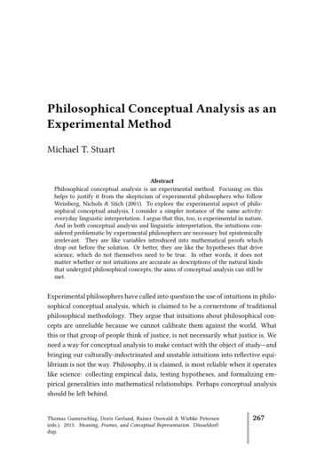
8D. Skoutas, A. Simitsis, and T. Sellis3.2The type graphIn the following, we describe an approach for designing an ETL process throughgraph transformations based on the constructed ontology. One of the main advantages of this approach is that it allows to visualize the involved schemata, thedomain knowledge and the ETL operations, and to proceed with the design taskin either automated or interactive manner. As discussed in Section 2, the designof the ETL process is built in a step-by-step manner through a series of graphtransformations. Essential to this is the role of the ontology, which determinesthe context (i.e., the semantics) at each transformation step, thus determiningwhich ETL operations are applicable and in what order. The selected ETL operations are represented as additional nodes and edges forming paths (flows) thatlead from the nodes of the source subgraph to the nodes of the target subgraph.The process of addressing this problem by means of graph transformationsis outlined in the following. We consider as starting point a graph comprisingthree subgraphs, namely the source, the target, and the ontology subgraphs.The main goal is then to define an appropriate set of rules, determining where,when, and how a flow of operations from a source to a target node can be created.Essentially, each rule is responsible for inserting an operator in the ETL flow.(Additionally, as we discuss at a later point, some rules aim at replacing orremoving operators from the flow.) The finally obtained graph is a supergraphof the initial graph, depicting the choice and order of the aforementioned requiredoperations.In the generated graph, ETL operations are represented by nodes, with incoming and outgoing edges corresponding, respectively, to the inputs and outputsof the operation. These form flows between source nodes and target nodes. Sincepopulating a target element with data from a source element often requires morethan one transformation to be performed on the data, in the general case theseflows will have length higher than 1. To allow for such functionality, we use thenotion of intermediate nodes. These refer to intermediate results produced by anETL operation and consumed by a following one. Consequently, the incomingedges of a node representing an ETL operation may originate either from sourcenodes or from intermediate nodes, while outgoing edges may be directed eitherto target nodes or to intermediate nodes.To formally capture such relationships, we introduce the type graph illustrated in Figure 1 and explained in detail below. The type graph specifies thetypes of nodes and edges that the instance graphs (i.e., those constructed tomodel data store schemata, annotations, and ETL flows) may contain, as wellas how they are structured. The type graph is depicted in Figure 1(a) and distinguishes the following types of nodes and edges:– Ontology nodes (OntNode): they represent concepts of the considered application domain. An ontology node may connect to other ontology nodes bymeans of isa, partOf, typeOf or connects edges. The connects edges correspond to generic relationships between concepts of the domain, and theyare represented in Figure 1(a) by continuous, unlabeled arrows; the isa,
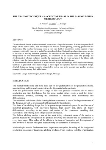
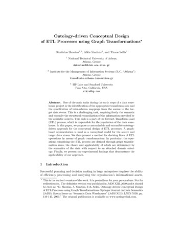
9typeOfisaSrcNodeString IDpartOfOntNodeString URIIntmNodeOperationString type(a)TrgNodeString IDtypeOfOntNodeURI ”ex:USD”SrcNodeID ”s:Salary”OntNodeURI ”ex:Salary”Operationtype ”CONVERT”typeOf OntNodeURI ”ex:EUR”TrgNodeID ”t:Salary”(b)Fig. 1. (a) The type graph and (b) a sample instance graph––––partOf, and typeOf edges are represented by continuous arrows with a corresponding label to distinguish the type of the relationship. Each ontologynode has an associated URI that uniquely identifies it.Source nodes (SrcNode): they correspond to elements of the source datastore schemata (e.g., tables or attributes in the case of relational schemata,or XML tree nodes in the case of XML documents). Each source node hasa unique ID (i.e., a URI), prefixed accordingly to indicate the data store itbelongs to. Source nodes may relate to each other by connects edges (corresponding, for example, to foreign keys in the case of relational sources or tocontainment relationships in the case of XML.) Source nodes are annotatedby ontology nodes, as shown by the dotted edge in Figure 1(a), to makeexplicit the semantics of the enclosed data.Target nodes (TrgNode): they are similar to source nodes, except from thefact that they refer to elements of the target data stores instead.Intermediate nodes (IntmNode): they are nodes containing temporary datathat are generated during ETL operations. They are also annotated by ontology nodes. This is necessary for continuing the flow of operations once anintermediate node has been created. Notice however the difference: sourceand target nodes are annotated manually (or perhaps semi-automatically)and these annotations need to be in place a-priori, i.e., at the beginning ofthe ETL design process. In fact, these annotations constitute the main driving force for deriving the ETL scenario. On the contrary, the annotations ofthe intermediate nodes are produced automatically, when the intermediatenode is created, and are a function of the type of ETL operation that createdthis node, as well as of the (annotation of the) input used for that operation.Operation nodes (Operation): they represent ETL operations. The attributetype identifies the type of the operation (e.g., filter or convert). The inputs and outputs of an operation are denoted by dashed edges in Figure 1(a).In particular, the input of an operation is either a source node or an intermediate node, whereas the output of an operation is either an intermediatenode or a target node. Each ETL operation must have at least one incomingand one outgoing edge.
10D. Skoutas, A. Simitsis, and T. SellisExample. A sample instance of the considered type graph is illustratedin Figure 1(b). It depicts a typical scenario where an ETL operation convertsthe values of a source element containing salaries expressed in U.S. Dollars topopulate a target element with the corresponding values in Euros.3.3The transformation rulesHaving the type graph introduced in the previous section, we can create instancesof this graph to represent specific instances of the ETL design problem, i.e., tomodel a given source graph, a given target graph, and their annotations withrespect to an associated domain ontology. The initial graph does not containany Operation nodes. Instead, the goal of the transformation process is exactlyto add such nodes in a step-by-step manner, by applying a set of correspondingtransformation rules. Recall from Section 3.1 that each such rule comprises twobasic parts: a) the left-hand-side (LHS), specifying the pattern that triggers theexecution of the rule, and b) the right-hand-side (RHS), specifying how the LHSis transformed by the application of the rule. Optionally, a rule may have a thirdpart, specifying one or more negative application conditions (NACs). These arepatterns preventing the triggering of the rule. A common usage of NACs is asstop conditions, i.e., to prevent the same rule from firing multiple times for thesame instance. This occurs when the RHS of the rule also contains the LHS.In the following, we introduce a set of rules used to construct ETL flows basedon the operations (and their conditions) described in Section 2, and describeeach rule in detail. Essentially, these rules are divided into groups, each oneresponsible for the addition of a certain type of ETL operation. We consider twokind of rules, referring, respectively, to simple and composite ETL operations.Rules for simple operations. This set of rules handles the LOAD, FILTER,CONVERT, EXTRACT, and CONSTRUCT operations.LOAD. This is the simplest operation: it simply loads data records from asource to a target element. For such a direct data flow to be valid, one of thefollowing conditions must apply: either a) the source element must correspondto a concept that is the same with that of the target element, or b) the sourceelement must correspond to a concept that is subsumed (i.e., has an isa link)by that of the target element. In the former case the rule pattern searches fora pair of source and target nodes that point to the same OntNode, as shownin Figure 2. If a match is found, the rule is triggered and a LOAD operation isinserted.In the latter case the pattern searches for a SrcNode that is annotated byan OntNode which has an isa relationship to another OntNode annotating aTrgNode (Figure 3.) Again, the transformation performed by the rule is to insert an Operation node of type LOAD, connecting the source and target nodes.Additionally, in the second case, it is also useful to have data flow to (or from)an intermediate node, which will then be further transforme
Informatica’s PowerCenter [5], Microsoft’s Data Transformation Services [6], and Oracle’s Warehouse Builder [7]. All these approaches, at the conceptual level, focus on the graphical design and representation of the ETL process, whereas the identi cation of the require