Transcription
PD SeriesInstruction, Operating & Maintenance ManualPD Series Gas Charged DampenersWell Service, Drilling, Slurry & Industrial Servicewww.performancepulsation.com sales@performancepulsation.com3309 Essex Dr. Suite 200, Richardson, Texas 75082 Phone: 972.699.8600 Fax: 972.699.86022018 All Rights Reserved Rev 6.22.2018
Pg 2PREFACEThis manual describes operating practices and maintenance procedures applicable to PD SeriesPulsation Dampeners manufactured by Performance Pulsation Control, Inc. The informationcontained herein reflects recommendations based on industry best practices and recognized safetyprotocols. Use of the information and procedures contained in this manual is voluntary and is to beimplemented at the sole discretion of the user.The user is at all times responsible for operating andmaintaining pulsation dampeners in a manner that is safe, conforms to the owner’s establishedbusiness practices, and is in conformance with applicable regulations.NOTE: Please read all instructions carefully before proceeding with the installation, operation, andcharging of this equipment. Contact Performance Pulsation Control for assistance or questionsconcerning the information in this manual. 2018 Performance Pulsation Control, Inc. All Rights Reservedwww.performancepulsation.com sales@performancepulsation.com3309 Essex Dr., Suite 200, Richardson, Texas 75082 Phone: 972.699.8600 Fax: 972.699.8602
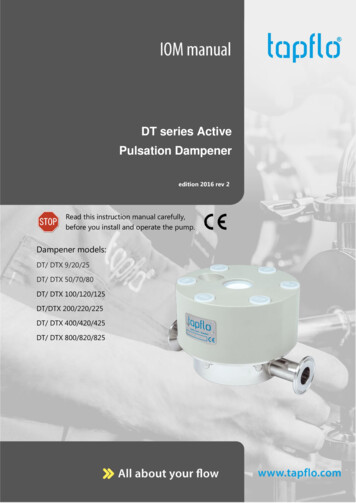
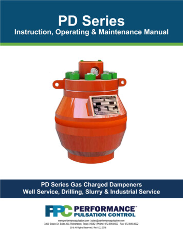
Pg 3INSTALLATIONMATERIALS NEEDED: API Seal Ring Grease Lubricant for Seal Ring Torque Wrench - Suitable for standard pipinginstallationINTRODUCTION:Mount the dampener as close as possible to the pumpfor maximum effectiveness, installing the dampenerwithin a length not to exceed 10 times the connectingpipe diameter. Installing the unit in a vertical orientationsuch that the fluid flows toward the bottom opening ofthe dampener to provide the greatest performance isrecommended.WARNINGDo not pre-charge the dampener until it has beensecurely mounted in place. Use only nitrogen gaswhen pre-charging!INSTALLATION INSTRUCTIONS1. Thoroughly clean the mounting flange faces andcheck that the API ring grooves have uniformsealing surfaces.2. Ensure the new API ring is clean and lightly coatedwith lubricant before installing in the mountingflange ring groove.3. Place the API ring into the groove on the mountingsurface of the pipe system.4. Ensure the cover plate on the dampener is firmlyattached.NOTE: Cover plate is installed, properly torqued,and sealed in the factory prior to shipment.WARNINGEnsure cover plate is firmly attached. Do not liftanything other than the dampener with the twolifting lugs or material failure may occur.6. Insert the flange mounting studs into the 8threaded holes in the bottom of the PD unit.NOTE: All studs should be seated to ensure thatthey are properly inserted. There should be lessthan 0.25' (6 mm) variation in installed height.7. Lower the dampener onto the mating flangeand API ring.8. Once seated, ensure the gap between themounting flange and dampener bottomconnection is equal around the circumference.9. Install the nuts onto the mounting studs andtighten using an alternating crisscross pattern tothe proper torque as listed below.NOTE: Torque values are for PerformancePulsation Control's Xylan coated studs and nuts.If using a lubricant, consult lubricant supplier orcontact PPC for new torque ecial Note: For PD units equipped with a 1-1/4”7NC socket head cap screw, the torque for thatfastener is 1175ft. lbs.5. Lift the dampener, turn it over, or lay it on its side togain access to the bottom threaded mounting holes.www.performancepulsation.com sales@performancepulsation.com3309 Essex Dr., Suite 200, Richardson, Texas 75082 Phone: 972.699.8600 Fax: 972.699.8602
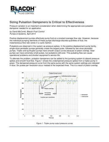
PRE-CHARGE THE DAMPENER WITH NITROGENMATERIALS NEEDED: Pure Nitrogen Gas – At greater pressure thandesired pre-charge pressure Regulator – Must accommodate desired precharge pressure Charging Hose Kit General Hand ToolsPg 4Pre-charging the diaphragm is accomplished byusing commercially available nitrogen cylinders. Thenumber of nitrogen cylinders required to pre-chargethe diaphragm will depend on dampener capacityand pre-charge pressure. The chart that follows isbased on the use of STD 224 cubic feet, 2200 PSIdry nitrogen cylinders.UnitWARNINGAlways pre-charge with NITROGEN! Verify thatNitrogen bottles contain pure nitrogen gas. Therehave been documented reports of both end usersand service providers using bottles containing allor up to 30% oxygen to charge their diaphragms/bladders. Those incidents led to catastrophicdampener explosions. This type of incidentrepresents a potential loss of life.The dampener must be isolated from the system (0PSIG) and fluid drained before pre-charging.INTRODUCTION:PPC recommends using a reputable nitrogengas supplier that can provide written bottle fillingprocedures and verification for nitrogen gas purity.PPC further recommends that each bottle be clearlymarked with an appropriate Compressed NitrogenGas Association shoulder label. All nitrogen gasbottles should come with a 580 - type valve unlessyou are using a bottle with a greater than 3000 psigpressure rating, which should have a 680 - typevalve installed.One of the most important factors in proper pulsationdampener performance is establishing the correctpre-charge pressure. Normally, the pre-chargepressure is based on charging the dampener up to75% of the minimum system operating pressure, toa maximum of 2500 psig (172.4 bar). As a generalrule, the pre-charge ratio (pre-charge pressure /operating pressure) should fall between 25% and75% at system operating conditions. Operating thedampener with a pre-charge ratio outside of thisrange will have potentially negative effects on thediaphragm service life.Cylinders RequiredPre-charge No. CylindersPressureRequired0 - 14001PD05 SeriesPD10 SeriesPD20 Series1400 - 16001600 - 22000 - 900900 - 15001500 - 25000 - 770770 - 13001300 - 250023123123CHARGING INSTRUCTIONS:1. Remove the valve cover by locating andremoving the two ½” bolts located on the valvecover.2. Ensure that all cover plate nuts are secured andevenly tightened according to the torque 33Special Note: For PD units equipped with a 1-1/4”7NC socket head cap screw, the torque for thatfastener is 1175ft. lbs.www.performancepulsation.com sales@performancepulsation.com3309 Essex Dr., Suite 200, Richardson, Texas 75082 Phone: 972.699.8600 Fax: 972.699.8602
CONT., PRE-CHARGE THE DAMPENER WITH NITROGEN3. Turn the charging valve clockwise until it stops toensure full closure; do not over-tighten.4. Remove the protective cap from charging valve.5. Install the regulator onto nitrogen source.6. Connect the charging hose assembly to thecharging valve and the regulator on the nitrogencylinder.7. Set the regulator to 0-psi.8. Open the charging valve by turning the 5/8” safetynut three full turns counter-clockwise.9. Check the pre-charge pressure in dampener withcharging kit gauge.NOTE: Charging hose gauge and dampener gaugeshould read the same pressure.10. Slowly open the nitrogen cylinder valve. With theregulator set to 0-psi there should be little or noflow in the charging hose line.11. Slowly adjust the regulator to allow nitrogen to flowuntil the recommended pre-charge pressure showson the regulator gauge.12. Allow the pressure in the dampener to build to theproper pre-charge pressure.Pg 5NOTE: When the pre-charge is complete, theregulator pressure, the charging hose pressure,and dampener pressure gauge should read thesame. Dampener gauge must read the same asother gauges. If not, replace dampener gauge.15. Slowly bleed the pressure from the charging hoseby slightly loosening the cylinder connection nutuntil the charging hose pressure gauge readszero. This should be done with caution. Releaseall pressure in the line before fully removing theconnection.16. Apply soapy water or similar leak detection fluidaround the fittings, connections, studs, and flangemating areas. Bubbles forming in the applied waterindicates a leak. If a leak is detected, re-tightenthe connections and check again. Reinstallation ofthe gauge or charging valve in the dampener maybe required to stop a leak.17. Remove the charging hose assembly and reinstallthe charging valve protective cap.18. Confirm the pre-charge pressure on the dampenerpressure gauge.19. Reinstall the valve cover and securely tightenthe ½” bolts to 56 ft-lbs of torque. Your pulsationdampener is now ready for operation.13. Close the charging valve by turning the safety nutfully clockwise until it stops and is snug.NOTE: Failure to properly close the charging valvewill result in nitrogen leaking out of the diaphragmand result in poor performance and earlydiaphragm failure.14. Close the nitrogen cylinder valve and reduce thepressure regulator to 0-psi to ensure no additionalgas comes out of the cylinder tank.NOTE: Additional cylinders may be required tobring the dampener to proper pressure. If additionalcylinders are required, repeat steps #5 through #14until the desired pressure is obtained.www.performancepulsation.com sales@performancepulsation.com3309 Essex Dr., Suite 200, Richardson, Texas 75082 Phone: 972.699.8600 Fax: 972.699.8602
DIAPHRAGM REPLACEMENTGENERAL INSPECTIONGENERAL INSPECTION1. Regularly observe the dampener pressure gaugeand ensure it is properly functioning. During pumpoperations it should display a similar pressureas the pump’s discharge pressure gauge. If itreads differently or no pressure at all, then thedampener gauge needs to be replaced.2. Inspect the pre-charge pressure on the dampenermonthly, or anytime the system is showing excessvibrations.NOTE: Pre-charge pressure should be checkedonly when the system pressure is at 0-psi.Pg 6MATERIALS NEEDED: Socket Wrench TFE Tape Emery Cloth General Hand ToolsDIAPHRAGM REPLACEMENTWARNING3. During pre-charge inspection, check the unitfor loose nuts, random debris, possible leaks,damage, corrosion, and overall general condition.Verify that your Nitrogen bottles contain purenitrogen (N2) gas. There have been documentedreports of both end users and service providersusing bottles containing all or up to 30% oxygen tocharge their diaphragms/bladders. These incidentsled to catastrophic dampener explosions. This typeof incident represents a potential loss of life!4. Tighten any loose fasteners, clear debris, andcorrect leaks. Note the cause of and seek tocorrect any corrosion or other damage. If damageis severe, contact PPC for a safety evaluation.1. Isolate the pulsation dampener from the pumpingsystem. Ensure that the system pressure reads0-psi.2. Remove the valve cover to gain access to thecharging valve. Keep hardware for reuse. Removethe protective cap from the charging valve. Turnthe 5/8” safety nut fully counter- clockwise toensure there is no pre-charge pressure left onthe system. Confirm the pressure is 0-psi on thepressure gauge.3. Attach properly rated lifting shackles and liftingdevice to the lift lugs on cover plate.4. Loosen the cover plate nuts using a crisscrosspattern and back the nuts away from the coversurface. Do not completely remove the nuts at thistime.WARNINGDo not remove the nuts completely until the coverplate has been lifted and it has been proven thereis no longer a pre-charge on the system. Reuse ofremoved diaphragm is not recommended.www.performancepulsation.com sales@performancepulsation.com3309 Essex Dr., Suite 200, Richardson, Texas 75082 Phone: 972.699.8600 Fax: 972.699.8602
Pg 7DIAPHRAGM REPLACEMENT5. Using a hoist, slowly and partially lift the coverplate with the provided lifting lug shackles untilthe rubber diaphragm seal has been broken andreleases any possible remaining nitrogen gas.6. Remove the cover plate nuts and remove thecover plate.15. Insert the folded diaphragm length-wise into thedampener and open it up inside the body of thevessel.7. Reach into the bottom of the bladder and removethe existing stabilizer bolt, lock washer, stabilizerplate, and stabilizer.17. Install the diaphragm stabilizer, stabilizer plate,lock washer and bolt. Tighten the bolt securelyusing a socket wrench.8. Install a lifting eye into the 1”-8NC hole at thebottom of the diaphragm and remove the existingdiaphragm.CAUTION9. Inspect the interior of the vessel for burrs, debrisor excess pitting. Mild scale or pitting may beremoved with the application of a light emerycloth. If excessive pitting, corrosion or wear isfound, contact a Performance Pulsation Controlrepresentative. If corrosion or wear is found duringinspection, all other pulsation dampeners shouldalso be inspected. Flush the shell before the newdiaphragm is reinstalled.10. Inspect the dampener bore and diaphragm sealingareas for burrs, nicks, or discontinuities that couldprevent sealing. Repair as necessary using an emery cloth.11. Inspect new diaphragm (refer to parts for properdiaphragm material) for any damage. Ensurethe new diaphragm is intact and free of anydiscontinuities.12. Coat the bore area and the diaphragm with a lightcoat of grease to aid in installation.13. Pull up on the neck of the diaphragm while pushingthe steel insert at the bottom down, elongating thediaphragm.14. Roll the sides of the diaphragm to form a footballshape, using a strap to hold it in this position.16. Adjust the neck of the diaphragm to fit uniformlyover the gasket surface of the dampener bore.Installation of the cover plate is the reverse ofremoval. Exercise care when lowering the coverplate to ensure that the diaphragm is not crushedor folded over on the diaphragm sealing surface.18. Hand-tighten the nuts onto each stud. Then tightenin a standard crisscross pattern until tightened tothe required torque cial Note: For PD units equipped with a 1-1/4”-7NCsocket head cap screw, the torque for that fastener is1175ft. lbs.19. Pre-charge the dampener in accordance withthe charging instructions found previously in thismanual and check for leaks.www.performancepulsation.com sales@performancepulsation.com3309 Essex Dr., Suite 200, Richardson, Texas 75082 Phone: 972.699.8600 Fax: 972.699.8602
REPLACING PRESSURE GAUGE & CHARGING VALVEPg 88. If replacing the charging valve, loosen the safetynut and remove the existing valve.MATERIALS NEEDED: General Hand Tools TFE TapeINTRODUCTIONPrior to performing any service on the pulsationdampener, determine if the dampener pressure isproperly functioning. A faulty gauge must be replaced.Failure to verify gauge is properly functioning can leadto poor performance, premature diaphragm failure,and possibly damage or injury.Gauge and charging valve are provided with a repair kitorder. See Appendix for repair kit info.When replacinggauge, ensure TFE tape is applied in the correctdirection of each part’s male thread to protect threadsand to ensure complete sealing. Proper direction issuch that the TFE tape doesn’t unwind when threadingthese parts into the cover plate.9. Prepare the new valve by wrapping the threadswith TFE tape. Wrap the tape in such a way anddirection to ensure that the TFE will not unwindwhen being installed.10. Install the new valve and ensure the safety nuthas been tightened properly.11. Pre-charge the dampener in accordance withthe charging instructions found previously in thismanual and check for leaks.1. Isolate the pulsation dampener from the pumpingsystem. Ensure that the system pressure reads0-psi.2. Bleed off the nitrogen pressure within the dampenerto 0-psi.3. Prepare the new gauge by wrapping the threadswith TFE tape. Wrap the tape in such a way anddirection to ensure that the TFE will not unwindwhen being installed.4. Remove the existing gauge.5. Thread the new gauge into the pulsation cover andtighten properly.6. Attach the warranty tag.7. If the charging valve is not being replaced, precharge the dampener in accordance with thecharging instructions found previously in thismanual and check for leaks.www.performancepulsation.com sales@performancepulsation.com3309 Essex Dr., Suite 200, Richardson, Texas 75082 Phone: 972.699.8600 Fax: 972.699.8602
Appendix
Pg 10PD MODEL DESCRIPTIONSAll Gas Charged Pulsation Control Equipment is designed to Section VIII Division I of the ASME Pressure Vessel Code.Specific certifications are available and are shown below.Model5 gallon 18.9 litersDescriptionPD05 MODELSOther certifications such as ABS, DNV, NR13available PED with CE stamp & GOSTavailable at an extra charge.Assembly Part NumberNBRHNBR(Nitrile Bladder)(Hydrogenated Nitrile Bladder)Continuous 0 F-212 F (-18 C-100 C)Intermittent 250 F (121 C)Continuous 0 F-250 F (-18 C-121 C)Intermittent 300 F (149 C)PD05-50005 Gallon 5000 psi - ASMEPD0550-01011-ASMEPD0550-07011-ASMEPD05-75005 Gallon 7500 psi - ASMEPD0575-01011-ASMEPD0575-07011-ASMEPD05-100005 Gallon 10000 psi - ASMEPD0510-01011-ASMEPD0510-07011-ASMEPD05-150005 Gallon 15000 psi - ASMEPD0515-01011-ASMEPD0515-07011-ASME5000 psi 344.7 bar7500 psi 517.1 bar10000 psi 689.5 bar15000 psi 1034.2 barPD10 MODELSModel10 gallon 38 litersDescriptionOther certifications such as ABS, DNV, NR13available PED with CE stamp & GOSTavailable at an extra charge.NBRAssembly Part NumberHNBRURETHANEContinuous 0 F-212 F(-18 C-100 C)Intermittent 250 F (121 C)Continuous 0 F-250 F(-18 C-121 C)Intermittent 300 F (149 C)PD10-500010 Gallon 5000 psi - ASMEPD1050-01011PD10-750010 Gallon 7500 psi - ABS-CDSPD01075-01011-ABS PD1075-07011-ABS5000 psi 345 bar7500 psi 659.5 barPD1050-07011Continuous 0 F-180 F(-18 C-82 C)Intermittent 220 F (104 C)PD1050-09011PD1075-09011-ABSPD20 MODELSModel20 gallon 76 litersDescriptionOther certifications such as ABS, DNV, NR13available PED with CE stamp & GOSTavailable at an extra charge.Assembly Part NumberNBRHNBRURETHANEContinuous 0 F-212 F(-18 C-100 C)Intermittent 250 F (121 C)Continuous 0 F-250 F(-18 C-121 C)Intermittent 300 F (149 C)Continuous 0 F-180 F(-18 C-82 C)Intermittent 220 F (104 C)PD20-144020 Gallon 1440 psi - 500020 Gallon 5000 psi - 0 Gallon 7500 psi - 11-ABS1400 psi 99 bar5000 psi 345 bar7500 psi 517 barwww.performancepulsation.com sales@performancepulsation.com3309 Essex Dr., Suite 200, Richardson, Texas 75082 Phone: 972.699.8600 Fax: 972.699.8602
Pg 1118.69”23.0”12.25”600 lbs474.7 mm584.2 mm311.2 mm272 kgAB20-3/8”24-1/8”517.525 mm612.775 mmCWeight18-1/4”705 lbs463.55 mm320 9 lbs536.575 mm673.100 mm495.300 mm4170 20 lbs704 mm743 mm552 mm644 kgAB24”612.8 mm28-9/16”23”1917 lbs725.4 mm584.2 mm870 kgWeight24-1/8”28-7/8”23-1/8”1917 lbs612.8 mm733.5 mm587.4 mm870 kgPD20-1440ABCWeight21-1/2”28-7/8”24-1/4”682 lbs.546 mm733 mm616 mm309 kg.ABCWeight27-3/8”33-5/8”27-1/8”1851 lbs.695.4mm854.1 mm689 mm840 kg.AB30-1/2”35-7/8”774.7 mm911.2 mmCWeight29-1/8”2759 lbs.739.8 mm1252 WeightPD20-5000PD MEASUREMENTS & PART NUMBERSCWeightABCwww.performancepulsation.com sales@performancepulsation.com3309 Essex Dr., Suite 200, Richardson, Texas 75082 Phone: 972.699.8600 Fax: 972.699.8602
Pg 12PD05 PARTS n.com sales@performancepulsation.com3309 Essex Dr., Suite 200, Richardson, Texas 75082 Phone: 972.699.8600 Fax: 972.699.8602
Pg 13PD05 CONNECTION SIZING & PART NUMBERSPD05 CONNECTION tion3-1/8” API 5k2-9/16” API 10k2-9/16” API 10k2-9/16” API 15kRing GasketR35BX153BX153BX153PD05-5000PD05 PART NUMBERSPD05-7500PD05-100001VALVE COVER BOLTPD05-VCBPD05-VCBPD05-VCBPD05150-VCB2VALVE COVERPD05-VCPD05-VCPD05-VCPD05150-VC3PRESSURE GAUGEPD0550-PGPD05-PGPD05100-PGPD05150-PG4LOADING G TAGPDWTAG1PDWTAG1PDWTAG1PDWTAG16COVER PLATEPD0550-CPPD0575-CPPD05100-CPPD05150-CP7COVER PLATE STUD(8 VER PLATE NUT(8 NNECTION STUD(8 Req.- shipped ST10CONNECTION NUT(8 Req.- shipped 1DIAPHRAGMPD05-01 NBRPD05-07 HNBRPD05-01 NBRPD05-07 HNBRPD05-01 NBRPD05-07 HNBRPD05-01 NBRPD05-07 HNBR#DESCRIPTIONwww.performancepulsation.com sales@performancepulsation.com3309 Essex Dr., Suite 200, Richardson, Texas 75082 Phone: 972.699.8600 Fax: 972.699.8602PD05-15000
Pg 14PD 10 & 20 PARTS ncepulsation.com sales@performancepulsation.com3309 Essex Dr., Suite 200, Richardson, Texas 75082 Phone: 972.699.8600 Fax: 972.699.8602
Pg 15PD 10 & 20 SIZING & PART NUMBERSPD10 CONNECTION SIZINGPD10-5000PD10-7500Connection4 1/6" API 5K4 1/16" API 10KRing GasketR39BX155PD20 CONNECTION SIZINGPD20-1440PD20-5000PD20-7500Connection4" ASME Class6004 1/16" API 5K4 1/16" API 10KRing GasketSpiral WoundGasketR39BX155ITEMDESCRIPTIONPD 10 PART NUMBERSPD10-5000PD10-7500PD20 PART NUMBERSPD20-1440PD20-5000PD20-75001VALVE COVER BOLTPD10-VCBPD10-VCBPD20-VCBPD20-VCBPD20-VCB2VALVE COVERPD10-VCPD10-VCPD20-VCPD20-VCPD20-VC3PRESSURE 4aLOADING VPD2075-LV4bLOADING VALVE(CGA680)VLV CGA680SHERWOODVLV CGA680SHERWOOD4cLOADING VALVE(CGA677)5WARNING TAGPDWTAG1PDWTAG1PDWTAG1PDWTAG1PDWTAG16COVER PLATEwith lift P7COVER PLATE STUD(12 75-CPS8COVER PLATE NUT(12 75-CPN9ADAPTER PS10ADAPTER P11ADAPTER PLATECAPSCREW (8 D2075-BPCS12CONNECTION STUD(8 D2075-BPST13CONNECTION NUT(8 Req.-ship 075-BPN14DIAPHRAGMNBR P/N: PD10-01HNBR P/N: PD10-07URETHANE P/N: PD10-09NBR P/N: PD10-01HNBR P/N: PD10-07URETHANE P/N:PD10-09NBR P/N: PD20-01HNBR P/N: PD20-07URETHANE P/N: PD20-09NBR P/N: PD20-01HNBR P/N: PD20-07URETHANE P/N: PD20-09NBR P/N: PD20-01HNBR P/N: PD20-07URETHANE P/N: PD20-0915NBR PD20-ST-0116STABILIZER PLATEPD10-ST-PLTPD10-ST-PLT PD20-ST-PLTPD20-ST-PLTPD20-ST-PLTVLV CGA677SHERWOODwww.performancepulsation.com sales@performancepulsation.com3309 Essex Dr., Suite 200, Richardson, Texas 75082 Phone: 972.699.8600 Fax: 972.699.8602
Pg 16PD05 DIAPHRAGM & REPAIR KITSPD05-5000PD05 PART NUMBERSPD05-7500PD05-1000011DIAPHRAGMPD05-01 NBRPD05-07 HNBRPD05-01 NBRPD05-07 HNBRPD05-01 NBRPD05-07 HNBRPD05-01 NBRPD05-07 HNBR12NBR #DESCRIPTIONPD05-1500013STABILIZER 4STABILIZER 15STABILIZER ABILIZER BOLT 1513 STABILIZER PLATESTABILIZER LOCKWASHER 1412 NBR STABILIZER11 DIAPHRAGMDESCRIPTIONPD05-5000Kit Includes #11-15:Diaphragm, NBR Stabilizer, StabilizerPlate, Stabilizer Lockwasher,Stabilizer BoltPD05-01-DKPD05-07-DK3PRESSURE GAUGE4DESCRIPTIONKit Includes #3,4,5 & 9:Pressure Gauge, Loading Valve,Warning Tag, Connection StudCharging valvePD05 DIAPHRAGM KIT PART -07-DK5 WARNING TAGPD05-01-DKPD05-07-DKPD0515-01- DKPD0515-07-DK9 CONNECTION STUDSPD05-5000REPAIR KIT ation.com sales@performancepulsation.com3309 Essex Dr., Suite 200, Richardson, Texas 75082 Phone: 972.699.8600 Fax: 972.699.8602
PD10 & 20 DIAPHRAGM & REPAIR KITS#DESCRIPTIONPD10-5000Pg 17PART NUMBERSPD10-7500PD20-1440 PD205000PD20-750014DIAPHRAGMPD10-01 NBRPD10-01 NBRPD10-07 HNBRPD10-07 HNBRPD10-09 URETHANE PD10-09 URETHANEPD20-01 NBRPD20-07 HNBRPD20-01 NBRPD20-07 HNBRPD20-01 NBRPD20-07 HNBR15NBR PD20-ST-0116STABILIZER D20-ST-PLT17STABILIZER LOCKWASHER 18STABILIZER 20-ST-BLTSTABILIZER BOLT 1816 STABILIZER PLATESTABILIZER LOCKWASHER 1715 NBR STABILIZER14 DIAPHRAGMDESCRIPTIONKit Includes #14-18:Diaphragm, NBR Stabilizer, StabilizerPlate, Stabilizer Lockwasher,Stabilizer BoltPD10-5000DIAPHRAGM KIT PART SURE GAUGEDESCRIPTIONKit Includes #3,4,5 & 12:Pressure Gauge, Loading Valve,Warning Tag, Connection Stud4b LOADING VALVE5 WARNING TAG9 CONNECTION STUDSPD10-5000REPAIR KIT NUMBERSPD10-7500 201440-01-RPD201440-RKwww.performancepulsation.com sales@performancepulsation.com3309 Essex Dr., Suite 200, Richardson, Texas 75082 Phone: 972.699.8600 Fax: 972.699.8602PD2050-01-RPD2050-07-RK
One of the most important factors in proper pulsation dampener performance is establishing the correct pre-charge pressure. Normally, the pre-charge pressure is based on charging the dampener up to 75% of the minimum system operating pressure, to a maximum of 2500 psig (172.4 bar). As a