Transcription
SmartWave BoxUser ManualSmartWave BoxUser ManualVersionDateStatus1.007-07-2009Final draftDocument dataProject OwnerProject ManagerProject CodeDocument TitleFile NameArchive NameKey WordsStatus: Final draftCOLLIS 2006 133 (SmartWave Box)SmartWave Box. User ManualSmartWave user manual CE FCC 1.0.dociVersion: 1.0
SmartWave BoxUser ManualTABLE OF CONTENTS1Introduction . 11.11.21.3Scope of document . 1Intended audience . 1Terminology . 12Product Description . 22.1Shipping group . 23System Requirement . 33.13.2Hardware requirements . 3Software requirements . 34Installation. 45Functional Description . 55.15.25.35.45.5Housing . 5LEDs . 5Connectors . 5Terminal / Card side. 6Modes of operation . 65.5.1 Analyzer mode . 65.5.2 Interceptor mode . 75.5.3 Card reader mode . 75.5.4 Card emulator mode . 75.5.5 Passive spy mode . 86Communicating with the SmartWave Box . 96.16.2Host interface protocol . 9Tag types . 107Appendix . 127.17.2Technical Information . 12CE/FCC Statement . 128Support . 13References . 14Status: Final draftiiVersion: 1.0
SmartWave BoxUser Manual1INTRODUCTIONThe SmartWave Box, a hardware device, is the perfect solution for testing contactless cards. Itcan read and simulate contactless smart cards; and also can analyze or spy the communicationbetween a contactless card and terminal.With its various modes of operation, the SmartWave Box is the most versatile tool availabletoday for contactless testing.1.1 Scope of documentThis the user manual describes how to setup and use the SmartWave Box.1.2 Intended audienceThis document is intended for the user of the SmartWave Box. Audiences are assumed to havea fair understanding of the standards related to smart cards and CL cards and related tests.1.3 TerminologyTo avoid confusion the term ‘internal terminal’ is used to refer to the internal active antenna ofthe terminal side of the SmartWave Box, the internal terminal communicates with the Cardunder-test (CUT). The external passive antenna is referred as the ‘(CL) probe’ andcommunicates with the Terminal-under-test (TUT).Status: Final draft1/12Version: 1.0
SmartWave BoxUser Manual2PRODUCT DESCRIPTION2.1 Shipping groupSmartWave BoxSmartWave ProbeFirewire cableUSB cableAC/DC power adapterSuckersStatus: Final draftOne (1) unitOne (1) unitOne (1) unitOne (1) unitOne (1) unitTwo (2) units2/12Version: 1.0
SmartWave BoxUser Manual3SYSTEM REQUIREMENT3.1 Hardware requirements A free USB port in your PC, support up to USB v2.0.No special requirement for memory size, please check the software application usermanual for corresponding information.3.2 Software requirements Collis test tools may need to be installed in order to use the full functionality of theSmartWave Box.Please contact Collis for software applications information.Status: Final draft3/12Version: 1.0
SmartWave BoxUser Manual4INSTALLATIONPlease use the installation procedure below to setup the SmartWave Box: STEP1Carefully unpack the contents of the shipping group. STEP2Use Fireware cable to connect the SmartWave box with the SmartWave probe. STEP3Connect the SmartWave Box to PC with provided USB cable. STEP4Connect power adapter to the SmartWave Box.Now the box is powered up. The power LED on the box will be turned on. And a beepsound will be generated by the box after initialization. STEP5Install the driver for the SmartWave box by following the driver installation wizard onyour system.Note: The SmartWave Box driver will be installed automatically when installing relatedCollis Test Tools.Then the SmartWave box is ready to use, you may need to install other software from Collis towork together with the SmartWave box. Please check the application user manual for furtherinformation.Status: Final draft4/12Version: 1.0
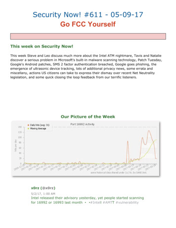
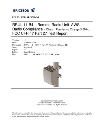
SmartWave BoxUser Manual5FUNCTIONAL DESCRIPTION5.1 HousingThe SmartWave Box has about the same size as the SmartLink Box. The antenna of the internalterminal is placed underneath the top cover and its position is clearly marked. On the back ofthe SmartWave Box a power connector, a USB connector and the CL probe connector areplaced. On the front of the box are LEDs which shows CL card, terminal status andcommunication. The front also carries test connectors to view information on an oscilloscope.Fig. 1 The SmartWave Box5.2 LEDsThe SmartWave Box has the following LEDs:PowerRed LEDIntern Tx/RxTri-color LED, green Data Rx, red Data TxProbe Tx/RxTri-color LED, green Data Rx, red Data TxInternal terminal RFTri-color LED, green RF only, amber RF and modulationCL probe RFTri-color LED, green RF only, amber RF and modulationThe communication signaling of the tri-color LEDs is stretched, i.e. short frames are show asbeing longer.5.3 ConnectorsThe SmartWave Box is fitted with the following coaxial connectors for connection with anoscilloscope:Internal terminal RFInternal raw data (Rx)Internal Tx dataExternal terminal RFExternal raw data (Rx)Status: Final draftBuffered antenna RF signal of the internal terminalRaw Rx dataTransmit dataBuffered antenna RF signal of the internal terminalRaw Rx data5/12Version: 1.0
Collis Test Tools. Then the SmartWave box is ready to use, you may need to install other software from Collis


![[ANS AQT80] - FCC ID](/img/3/user-manual-pdf-2735955.jpg)
![Ticket: # 3011470 - Re: [FCC Complaints] Re: Billing](/img/9/fcc-complaints-from-alabama-residents-2.jpg)