Transcription
Test ManualforBunk Bed Entrapment Hazards16 C.F.R. Part 1213, Part 1513, and Section (§) 1500.18Revised May 2002U.S. Consumer Product Safety CommissionWashington, D.C.http://www.cpsc.gov
TABLE OF CONTENTS1. Scope.12. Background .13. Definitions of Bunk Bed Components.14. Equipment Needed.25. Summary of Requirements for Bunk Beds .2a. Entrapment Requirements.2b. Marking and Labeling Requirements.3c. Instruction Requirements .36. Preliminary Set-up for Compliance Testing .37. Bunk Bed Test Procedures.3a. Guardrails.3b. Upper Bunk End Structure.9c. Lower Bunk End Structure.9d. Neck Entrapment .11e. Labeling .13f. Instructions .15Appendix A - Bunk Bed Test Report Form .16i
1.ScopeThis test manual is intended as a guide for U. S. Consumer Product Safety Commission(CPSC) staff to use for compliance testing of bunk beds. Manufacturers and distributorsmay also use this as a guide for performing their own tests. This test manual is not amandatory standard. The mandatory standards for bunk beds are set forth in theapplicable regulations in the Code of Federal Regulations (C.F.R.), at Title 16 C.F.R.Parts 1213 and 1513, and § 1500.18 (a). These standards are intended to assure thatopenings in a bunk bed are not of a size and shape that can entrap a child’s head andneck.2.BackgroundOn December 22, 1999, the CPSC published new rules for bunk beds codified at16 C.F.R. Parts 1213 and 1513, and § 1500.18 (a). Part 1213, “Safety Standard forEntrapment Hazards in Bunk Beds,” pertains to bunk beds intended for use by adults.Part 1513, “Requirements for Bunk Beds,” pertains to bunk beds intended for use bychildren. Section 1500.18 provides that a bunk bed that does not comply with Part 1513is a banned children’s article.The rules set forth requirements for bunk beds to reduce or eliminate the risk thatchildren will become trapped in openings or guardrails or other specific structures in thebed. This test manual includes the following information for the testing of bunk beds:a. testing methods for testing bunk beds to assess compliance with the requirements ofthe standard;b. specifies the tools needed for testing, such as a wedge block probe, guardrailtemplate, spherical probe, and neck-entrapment probe; andc. provides a report form (Appendix A) to record the test results.An ASTM standard, ASTM F-1427-96, “Standard Consumer Safety Specification forBunk Beds,” contains additional requirements that address other bunk bed hazards, suchas structural integrity.3.Definitions of Bunk Bed Componentsa. Bunk bed: a bed in which the underside of any foundation is over 30 inchesfrom the floor.b. Bed end structure: an upright unit at the head and foot of the bed to whichthe side rails attach.c. Foundation: the base or support on which a mattress rests.d. Guardrail: a rail or guard on a side of the upper bunk to prevent a sleepingoccupant from falling or rolling out.e. Side Rail: a rail attached to a bed end structure to which the foundation supportsystem is fastened.1
4.Equipment Neededa. Tools specified for assembly of the bunk bed by the manufacturer’s instructions;b. Tools and equipment in the Investigators Bunk Bed Test Kit, ircle guardrail template.Wedge block. See Figure 3.9-inch diameter rigid spherical probe. See Figure 4.Neck entrapment probe. See Figure 5.Force gage: range 0 to approx. 50 lbf ( 1 lbf)0.22-inch finger probe (unarticulated)10 to 12-ft. tape measureStop watch or a watch with a “seconds” hand45-degree triangle and a small level, or an inclinometerColored wax pencils (blue, red, white, and black)c. One camera (35mm or digital)d. Blank copy of the Bunk Bed Test Report form (Appendix A) to fill out.NOTE: The test kit is available for use by CPSC Laboratory or Field Operations staffonly.5.Summary of Requirements for Bunk Beds16 C.F.R. Parts 1213 and 1513 contain three basic sets of requirements that a bunk bedmust meet. These are summarized as follows:a. Entrapment Requirements: Entrapment requirements are established forguardrails and the end structures of bunk beds. (16 C.F.R. § 1213.3 and 1513.3) Each bunk bed must have at least two guardrails, one on each side of the bed, foreach bed with the underside of its foundation more than 30 inches from the floor.The top of the guardrails must be at least 5 inches above the surface of thethickest mattress the manufacturer recommends.The guardrail intended for the wall side must be continuous between the endstructures.The non-wall side guardrail can have an opening up to 15 inches wide betweeneach end of the guardrail and an end structure.The upper edge of each of the upper end structures must be at least 5 inchesabove the top surface of the mattress for at least half the distance between the twoposts or corners at the head and foot of the upper bunk.Testing for entrapment requires that the test operator check three areas: theguardrails, and the end structures of both the upper and lower bunks.2
In each area, one or more of the three probes - the wedge block probe, thespherical probe, and the neck-entrapment probe – are used to check for potentialentrapment hazards.b. Marking and Labeling Requirements: A bunk bed must have specified labels on thebed frame that identify the manufacturer or importer, model information, as well aswarn the user about safety issues. (16 C.F.R. § 1213.5 and § 1513.5)c. Instruction Requirements: The standard requires that assembly instructionsaccompany each bunk bed set. They must specify the mattress size. They mustinclude a warning to consumers against certain practices and uses that could beunsafe. (16 C.F.R. § 1213.6 and 1513.6)6.Preliminary Set-Up for Bunk Bed TestingThis section describes the steps necessary to prepare a bunk bed for testing.7.a.Before testing the bed, make sure it is assembled according to the manufacturer’sinstructions and that all the test equipment is available.b.Before conducting any of the tests, fill out the Bunk Bed Identification andDimensions section using a copy of the Bunk Bed Test Report Form contained inAppendix A.c.Photograph the assembled bunk bed in its entirety. During testing, photographparts of the bunk bed that are found to be non-complying.Bunk Bed Test ProceduresThe bunk bed is evaluated using the following procedure, which reflects all of thestandard’s requirements for guardrails, end structures, labeling and instructions. Theprocedure is presented in the same sequence as stated in the regulations. The testoperator may choose an alternate sequence to minimize installing and removing themattress. A videotape that demonstrates the test procedure is available. The testoperator records test results on a copy of the Bunk Bed Test Report Form (located inAppendix A) for submittal to the CPSC Office of Compliance.a.Guardrails: Check to see if the guardrails meet the general requirements at16 C.F.R. § 1213.3 (a) or § 1513.3 (a).i.Measurements can be taken with the tape measure, quarter-circle templateand finger probe available in the test kit.ii.Does each bed with the underside of its foundation greater than 30 inchesoff the floor have at least two guardrails, one on each side of the bed?3
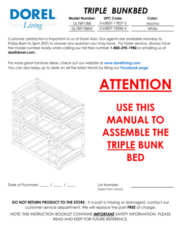
iii.One guardrail must be continuous between each of the bed’s end structures,and be at least 5 inches above the maximum mattress height recommendedby the manufacturer for the entire length. The continuous guardrail mayend at the head and/or foot of the bed in a quarter-circle bend that is equal toor above the quarter-circle shown in Figure 1. Use the quarter-circletemplate supplied in the test kit. Adjust the template so that the top of thetemplate is 5 inches above the top of the maximum thickness mattress andfoundation recommended by the manufacturer. Compare the area of theguardrail to the quarter-circle template. All parts of the guardrail must be atleast as high as, or higher than the quarter-circle template when viewedfrom the side.1) The “continuous” requirement allows a small gap between the guardrailand the end structure that shall not exceed 0.22 inches. The purpose of thisrequirement is to prevent a child from getting his or her finger trapped. Usethe finger probe in the test kit to make this assessment. Is the gap betweenthe end of the guardrail and the end structure below the level of themaximum thickness mattress less than or equal to 0.22 inches at each end?(Answer “Yes” if the gap is smaller than the finger probe and prevents theprobe from sliding down the gap to the foundation level.) If the top edge ofa guardrail is straight across and physically attached to the end structure,(i.e. no gap between the top surface/edge of the guardrail), the “continuous”requirement is met. See Figure 1.2) Is the continuous guardrail at least as high, or higher than the quartercircle template in the zone that is within 5.22 inches of the end structure?See Figure 1.3) Between the two 5.22-inch wide zones at the head and foot of the bed,the guardrail should stand at least 5 inches above the maximumrecommended mattress thickness for the entire length of the guardrail. Withthe thickest mattress the manufacturer recommends, measure from the topof the thickest mattress to the top of the guardrail of the upper bunk on thebed. If the thickest mattress is not supplied, mark the height of the thickestmattress on the bed frame (with a contrasting color using a wax pencilsupplied in the CPSC test kit), and measure from the marked point. Doesthe upper edge of the continuous guardrail stand 5 inches or more above thethickest mattress recommended by the manufacturer over its entireremaining length (above the 5.22-inch zones at the head end structure)?See Figure 1.4
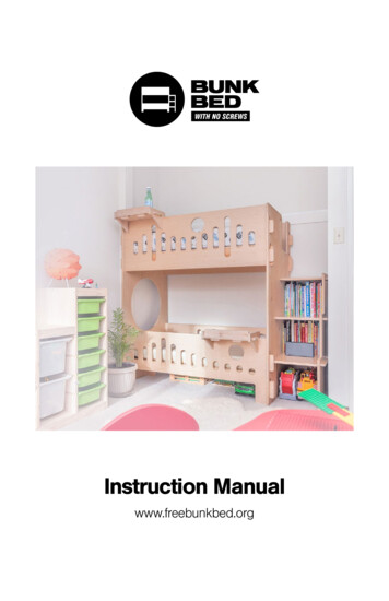
Figure 1 – Quarter-circle Continuous Guardrailiv.v.The other guardrail (non-wall side) must reach to within 15 inches of thenearest bed end structure. See Figure 2. Look at both ends of the guardrail.An opening in the middle is not allowed.1)Is the opening 15 inches or less between the guardrail and the bed endstructure at the height 5 inches above the thickest mattress?2)With the thickest mattress the manufacturer recommends, measurefrom the top surface of the mattress to the top of the guardrail of theupper bunk on the bed. If the thickest mattress is not supplied, markthe thickest mattress dimension on the bed frame (with a contrastingcolor of a wax pencil supplied in test kit), and measure from themarked point. The other (non-wall side) guardrail should stand atleast 5 inches or more above the mattress height at distances 15 inchesor more from the head of the bed’s end structure. Is the non-wall sideguardrail 5 inches or more above the maximum thickness mattress atall distances greater than 15 inches from either end structure?Check to see if the guardrails are securely attached. Are the guardrailsattached so that they can only be removed by either:1)intentionally releasing a fastening device; or2)applying forces sequentially in two different directions (e.g., up andover or vice-versa).5
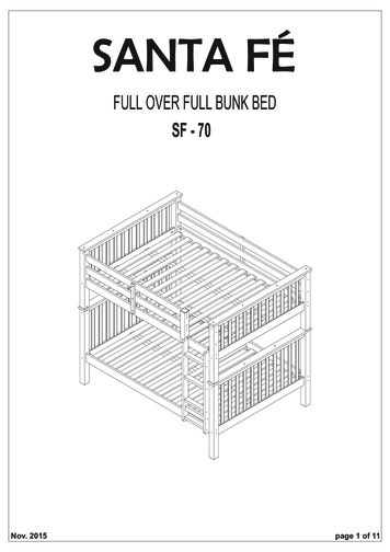
Figure 2 - Guardrail with Maximum 15-inch Gapvi.vii.Check to see if the bunk bed is designed to have a ladder or has a ladderattached to one side of the bed. If yes:1)Is the continuous guardrail located on the other side of the bed?2)Some bunk beds may have two continuous guardrails and a ladder, ormay have a ladder attached to the end structure.Check for upper bunk guardrail-foundation entrapment:1)If there is a mattress and/or foundation, remove it from theupper bunk bed.2)Look for openings in the area below the lower edge of the highestportion of the guardrail, and the underside of the upper bunk’sfoundation.3)Place the wedge block shown in Figure 3 (simulating a child’s torso)against each opening, tapered side first, and oriented so it is mostlikely to pass through the opening.4)Attach the force gage supplied with the test kit to the hook of thewedge block.6
5)Gradually pull in the direction perpendicular to the plane of the largeend of the wedge block. CAUTION should be exercised whilepulling on the wedge block to avoid injury if it pulls through.6)Pull for one minute with a force of 33-lbf.7)Repeat the test for each opening. Does each opening prevent thewedge block from passing through it?8)Describe the shape and location of openings that allow the wedgeblock to pass through. Document with photographs.7
Figure 3 - Wedge Block Probe8
b.Upper Bunk End Structure: Check to see if the upper bunk bed end structuresmeet the requirements of 16 C.F.R. § 1213.3 (b) and § 1213.4, or § 1513.3 (b)and § 1513.4.i. Check to see if the end structures are tall enough. With the thickest mattressand, if applicable, foundation the manufacturer recommends, measure from themattress surface to the top of the bed end structures. If the thickest mattress isnot supplied, mark the thickest mattress dimension on the bed frame (with acontrasting color of a wax pencil supplied in test kit), and measure from themarked point. The bed end structures should stand at least 5 inches above themattress height for at least 50 percent of the distance between the two posts ateach end of the bed. Measure at both the foot and the head of the upper bunk.ii. Check if there are potentially hazardous openings in upper bunkend structures:1)If there is a mattress and/or foundation on the upper bunk,remove it from the bed.2)Look for openings in the end structures above the foundation levelof the upper bunk.3)Place the wedge block (Figure 3) tapered side first, orientedso it is most likely to pass through, in all possible openings.Do all openings in the upper bunk bed end structures preventthe wedge block from passing through freely?Note: The 33-lbf application does not apply to § 1213.4 (b)or § 1513.4 (b) tests for end structures.c.Lower Bunk End Structure: Check to see if the bed end structures meet therequirements of 16 C.F.R. § 1213.3 (b) and § 1213.4 (c), or § 1513.3 (b) and§ 1513.4 (c).i.Check for potentially hazardous openings in the lower bunk end structures:1)Remove any mattress from the lower bunk bed.2)Look for openings in the area of the lower bunk end structure, locatedbetween the underside of the foundation of the upper bunk bed andthe upper side of the foundation of the lower bunk bed.3)Place the wedge block (tapered side first) oriented so it is most likelyto pass through in all possible openings. If each opening prevents thewedge block from passing through, stop here.9
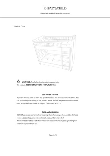
4)If the wedge block passes through, see if a 9-inch diameter rigidsphere freely passes through. See Figure 4. (The spherical probe,simulating a child’s head, is supplied with the test kit). Is the openinglarge enough to freely pass the 9-inch rigid sphere? If the answer is“Yes,” proceed to the neck entrapment test. If the answer is “No,”describe the shape and location of the opening that does not complywith this requirement. Document with photographs and attach theseto the report form with proper references and annotation.Figure 4 – 9-inch diameter Spherical Probe with Handleii.Repeat above test procedure with the specified maximum thickness mattress(recommended by the manufacturer) and foundation installed. Are therepotentially hazardous openings in the lower bunk bed end structures with themattress installed? (If the mattress is not available, mark the height of mattresson end structure with a wax pencil).1)Look for openings in the lower bunk end structures.2)Against each opening of the end structure, place the wedge block taperedside first, oriented so it is most likely to pass through.3)If the wedge block passes through, see if the 9-inch diameter spherefreely passes through. Is the opening large enough to freely pass the9-inch rigid sphere? If the answer is “Yes,” proceed to the neckentrapment test. If the answer is “No,” describe the shape and location ofthe opening that does not comply with this requirement. Document withphotographs and attach these to the report form with proper referencesand annotation.NOTE: The 33-lbf application does not apply to § 1213.4 (c) or § 1513.4 (c) testsfor end structures.10
d.Neck Entrapment: Observe if the geometry of the lower bunk bed end structureopenings may trap a child’s neck. Each end structure opening that passes thewedge block and the 9-inch sphere, must now be tested for neck entrapment(16 C.F.R. § 1213.4 (c)(3)(i) and (ii) or § 1513.4 (c)(3)(i) and (ii)). Use the neckentrapment probe shown in Figure 5. Note that the A-section and B-section of theprobe may be separated from each other during the test to accommodate differentgeometries. The A-section represents a child’s head, the B-section represents achild’s neck.i.Insert the A-section (separated from the B-section of the probe, if necessary)into each opening as follows.ii.Align the plane of the probe so it is parallel to the plane of the opening. SeeFigure 6.iii.Hold the front of the probe centered on and perpendicular to the centerlineof the opening.iv.Move the probe in towards the “narrowing space” keeping it centered andperpendicular until it contacts the boundaries of the opening, as shown inFigure 6.(0.75 inch [19 mm] thick)Figure 5 – Neck Entrapment Probe11
Figure 6 - Test Probe Simultaneously Touching BothSides Boundaries of OpeningDo the sides of the A-section of the probe simultaneously touch the boundary, asshown in Figure 6? If only the corners of the front end (1.88” dimension) of theA-section of the probe touch the boundaries but none of the side portions of theprobe touch the boundaries, then the boundary section does not pose a potentialfor neck entrapment. For example, most rectangular and square openings(90-degree corners) will meet the requirements of this section.If the sides of the A-section of the probe simultaneously touch the boundary, then:1)Mark both points on the boundary where the A-section touches it.2)Remove the A-section of the probe, if necessary, and place the B-sectioninto the opening. The A-section and B-section of the probe may beseparated from each other during the test to accommodate differentgeometries.3)As shown in Figure 7, align the B-section of the probe perpendicular to theplane of the opening.4)Hold the neck portion of the B-section of the probe midway between thetwo marks that were made with the A-section end and perpendicular to thecenterline of the opening as in Figure 7.5a)Move the neck section of the probe into the narrowing space beyond the twomarks.12
Figure
Bunk Beds,” contains additional requirements that address other bunk bed hazards, such as structural integrity. 3. Definitions of Bunk Bed Components a. Bunk bed: a bed in which the underside of any foundation is over 30 inches from the floor. b. Bed end structure: an upright unit at the