Transcription
AD-AOBI 791HARRYDIAMONDLABS ADELPHI MOF/0 13/11FOR LEAK DETECTIONIN LIQUID -(TC(U)ANALYSESOF ULTRASONICFLOWMETERSDEC 79 S E GFHMAN,A B HOLMESUNCLASSIFIEDHDL-TR-19077A-LAENDML.
L2 53uuu -,.ILA3I-II.I25 1111.4 II11.6MICROCOPY RESOLUTION TESTCHARTNANUONALBUR[AU) OF SIANDAVDS 1963 A
-IRV-KD012 911t
-AI
aUNCLASSIFIEDSECURITY CLASSIFICATION 0F THIS PAGE (When DateButw)REPORT DOCUMENTATION PAGEREAD INSTRUCTIONSCPINSCTLGUMEJ1 HDL-TR-l?47.12GOTACSINN.A,4 !1LES-/h fg---Ad1eline,20783MINI SOORO.6OGRACTNAMUANBADRESCOTRCORTRLLN asehigo,MDC 20242*UNa DCLASSIFIEDINOWNRONSCHEDULE16. DISTRIBUTION STATEMENT (of this Report)Approved for public release; distribution unlimited.17.DISTRIBUTION STATEMENT (of the abstr.ct ented lIn Block 2.itdifferent Ioa Report)IS. SUPPLEMENTARY NOTES*36AADRCMS Code:365734HDL Project No:This program was sponsored by the U.S. Geological Survey, Researchand Development Program of OCS Oil and Gas operationsIt.*KEY WORDS (Cmntiflus on evsro side If nocoseay sad iden tify by block number)Ultrasonic flowmetersLiquid measurementCrude oil measurementLeak detectionX& AWVIIACT (0.0F4orDOeof&s.N emendI dealt by block mbrA program was conducted to determine repeatability andlinearity of the ultrasonic time-delay types of flowmeters, sothat their applicability to leak detection on underwater pipelinescould be assessed. Field tests using merchantable crude oil wereconducted on two off-the-shelf, commercially available flowmetersat a refinery meter proving station. These tests showed a shortmeters. Long-termterm repeatability of 0.2 percent for SIFICATIONt OF THIS P449 (Mon Dot* Eneasi)o
UNCLASSIFIEDWECUPITY CLASIFICATION OF THIS PAG6UO3m Dae Bq rx20.Abstract (Cont'd)(7 hours) repeatability was 0.6 percent for one meter and 2.5percent for the other.For a leak detection system in which line balance iscontinually computed and line packing is compensated for, slowdrifts in line balance due to drifts of meter factors can becompensated for by periodically adjusting meter factors. Fora meter with drift characteristics similar to those measured,a computerized simulation indicates that the probability ofdetecting a leak greater than 0.6 percent of the total flow in10 minutes is greater than 99 percent. The probability of afalse alarm for the same conditions is about once per week.UNCLASSIFIED24.b,,CURITY CLASSIFICATION OF THIS PAGMtg,Date E'II.'.
1, pFOREWORDPortions of this paper were published previously in the proceedingsof the 54th International School of Hydrocarbon Measurement.The contents of this report are not to be used for advertising,publication, or promotion.Acces sionl ForDX TA BBYD s3ai an d/orSpci al
CONTENTSPage1.INTRODUCTION . * .2.ULTRASONIC FLOWMETER OPERATION . .3.MERCHANTABLE CRUDE OIL TEST FACILITY . .L.T114.MERCHANTABLE CRUDE OIL TEST RESULTS .125.METER SIMULATION .156.SIMULATION RESULTS .187.DISCUSSION OF LEAK DETECTION APPLICATIONS .218.CONCLUSIONS .23.78.DISTRIBUTION . *.25FIGURESIMAPCO and Controlotron meter tubes .a2Ultrasonic flowmeter operating principle .93Ultrasonic meter characteristics .114Merchantable crude-oil meter test loop. . ,.125Test results for MAPCO meter .136Test results for Controlotron meter .7Repeatability of 30-barrel measurements8Computer-simulated gathering line .169Simulated meter drift (MAPCO meter characteristics) .1810Simulated false-alarm rate (MAPCO meter characteristics) .1911Simulated false-alarm rate (Controlotron meter. # .characteristics) . 0.0.12131520Simulated leak detection probability as a function of leak size(MAPCO meter characteristics) .5.""*-PAMSAMz1-22
W,--TABLESPage1.Detection Level (Percentage of Flow Rate)2.Summ ary of Test Results.*.* . .6for one False23
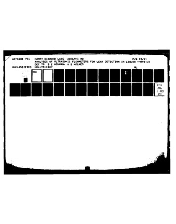
1.INTRODUCTIONThe U.S. Army's Harry Diamond Laboratories (HDL), under technologyhas been conducting a flowmeter evaluationtransfer authorization,program funded by the Conservation Division of the U.S. GeologicalThe overall objective of the program is to identify measurementsurvey.techniques that can be applied effectively and efficiently for improvingsafety and pollution control during operations on the outer continentalshelf .To further this objective, a program was initiated to determine nevflowmeter technologies that are potentially applicable to of fshore f lowmeasurement problems, particularly the problem of detecting underwaterThe hydrocarbon fluids handled by offshore pipelinespipeline leaks.typically have had the gas separated, but the liquid phase stillcontains salt water (up to 50 percent or even greater), some sand, andThe flow rate of this ray crude oilother sedimentary materials.historically has been impossible or highly impractical to measure byconventional means. The performance of positive displacement or turbinemeters that are used routinely for custody transfer of merchantablecrude oil or products would be seriously degraded by these fluids.A new meter was sought that could withstand the corrosive anderosive action of these fluids and that could meter the fluids reliablyfor leak detection, even though they may not be as accurate as custodyIn addition, to widen the potentialtransfer meters on clean crude oil.applicability of the meter to offshore problems by allowing the freepassage of pipeline pigs, a meter was sought that would not intrude intothe pipeline or require any pipeline diameter change.Meters were investigated that operated on the principles of vortexshedding, differential pressure, induced swirl, fluidic oscillators,magnetic flux, and time delay or doppler frequency shift during theThe only meter that met both thetransmission of ultrasonic sound.criteria of fluid suitability and no intrusion into the pipeline was theThe operation of this meter isultrasonic, time-delay type of meter.discussed in the next section, followed by the results of a field testof two meters of this type conducted at a merchantable crude meterproving station.Initially, six different meters from four manufacturers were to beOne manufacturer was to supply two differentincluded in this program.Another manufacturer was to supplymeters, but defaulted on delivery.prototypes of two experimental meters, but was not able to meet the testthat wereschedule due to late entry into the program.* The meterstested were the Clampatron flowmeter, manufactured by the ControlotronCorporation, and the NUSONICS flowmeter, manufactured by MAPCO, Inc.(both shown in fig. 1).7p.
CONTROLOTRONAPCO ,.Figure 1.2.MAPCO and Controlotron meter tubes.ULTRASONIC FLOWMETER OPERATIONEach testmeter was mounted on a 30-in.-long, schedule 40-A-106 pipespool, made of 6-in.-diameter carbon steel (grade B).The Controlotronmeter ultrasonic tranducers were clamped to the outside of the pipe sothat the sound passed through the wall of the pipe into the fluid beingmetered.The MAPCO meter transducers were mounted on bosses welded tothe pipe so that they were actually wetted by the fluid being metered.Both meters work on the principle of measuring timedelaydifferences between sound pulses transmitted upstream and downstream inthe flowing medium.The speed of sound in the flowing medium iseliminated as a variable because the flow rate calculations are based onthe reciprocals of the transmission times, as shown in figure 2.Although each manufacturer differs on the details in implementingthis calculation, the process generally used is to set the frequencies(fi) of two voltage-controlled oscillators (VCO's), one to be inverselyproportional to the upstream and the other to the downstream delay times(Ti) (i.e.,fi N/Ti where N is the proportionality constant).Thefrequencies can be set by filling a counter, beginning with thetransmission of a pulse and then comparing the fill time with thearrival time of the pulse at the other transducer.early, then the8* ,.if the counter fillsVCO frequency is decreased and vice versa.Each VCO
updated several hundred times per second with the arrivalfrequency isof either a valid upstream or a valid downstreamexcessively distorted pulse is received, nodifference between the two VCO frequencies (ortheir controlling voltages) is proportionalaveraged across the diameter of the pipe.signal. (If a noisy orTheupdate occurs.)the difference betweento the flow velocityPIEZOELECTIC CRYSALPIPE WALLTRA NUCER SPACINGFLOW VELOCrMDSOUND SPEED CDOWNSTREAM TRANSMISSION TIMEUPSTREAM TRANSMISSION TIMESSC V 19C-V C, TO EUMINATE SPEED OF SOUND (C)AS A VARIABLE1-,2VcuoTO SOLVE FOR SPEED OF SOUND1. 1N.2TZT,-IS21T,T,Figure 2. Ultrasonic flowmeter operating principle.The major difference betweendeciding when a sound pulse hasproblem can be understood onlyknown. From the equations shown(the average flow velocity) muchT-T2the flowmeters lies in their method ofbeen received. The magnitude of thiswhen the required timing precision isin figure 2, it can be shown that for Vless than C (the speed of sound),2-AT-ScosC21Vwhere T, and T2 are the downstream and upstream transmission times, S isthe transducer spacing, and 6 is the angle between the sound path andFor a 6-in.* pipe filled with a fluid with sound speedthe pipe axis.*in.x 25.4m m.9I.'; Ih
3000 ft/s,a velocity resolution of 0.005 ft/s (0.1 percent of 5 ft/)requires the time difference between upstream and downstream transitThis is about the timetimes to be known to 0.4 x 10- 9 s (0.4 ns).The sound frequency typicallyrequired for light to travel 5 in.transmitted through the fluid is about 1 MHz (a period of 10- 0 s), sothe received signal must be timed to within 4 x 10- 4 cycle.Circuitry that could accomplish this degree of timing precision cuittechnology.Thus, the most sensitive part of the ultrasonic flowmeteris the circuitry that detects the arrival time of the received soundpulse.Although every meter manufacturer has a different method ofdetecting the signal, both meters tested have circuitry to maintain aconstant received signal amplitude (by adjusting the transmitted signalamplitude) and to discriminate against signals that have been distortedor interfered with while transversing the pipe.Other details of thedetection circuitry vary considerably between manufacturers.However,the output of each meter is a pulse rate proportional to flow rate, soeach meter has a meter factor similar to any turbine or positivedisplacement meter.The output of the MAPCO meter was about 1300about 2000pulses/barrel;that of the Controlotron meter waspulses/barrel.-The accuracy of ultrasonic flowmeters depends on flow profile. Bothof the test meters are single-path meters (i.e., the velocity profile issampled only along a single line through the center of the pipe). As aresult, assumptions must be inade about the relationship between thevelocity averaged along a diameter and the velocity averaged over across section.These relationships are accurate for high Reynoldsnumbers, but are difficult to obtain for Reynolds numbers near thetransition region.Thus, two major factors can affect the accuracy of ultrasonicflowmeters:(1) the flow profile change as a result of flow velocityand viscosity variations and (2) electronic drift of meter zero due totiming errors. Figure 3 shows the effect of these sources of error onthe meter correction factor (i.e., a number that, when multiplied by theflow volume indicated by the meter, yields the correct volume passed bythe meter).In figure 3 are shown the variations of the meter factorresulting from two types of crude oil with viscosities differing by afactor of two, a positive and a negative zero shift of about 2 Hz (about0.001 barrel/s), and flow velocities from 500 to 4500 barrels/hr (atotal Reynolds number change from 16,500 to 280,000). The total changein the meter factor over these conditions is about 2 percent. The zeroerror dominates at low flow rates; the change in viscosity alone causesa shift of about 0.4 percent in the meter factor.010*" .1 I,-J
0.95-0 tIII--.a0.934, ,, "--,-.4008001200160020002400. 28003200400036004400FLOW RATE. BARRELS/HOURFigure 3.3.Ultrasonic meter characteristics (WTCoil, CHC Coastal Heavy crude oil). West Texas crudeMERCHANTABLE CRUDE OIL TEST FACILITYThe meters were tested on a flow loop through which various types ofcrude oil could be passed (shown in fig. 4).The crude oil was thenpassed through a mechanical displacement, bidirectional, running startstop meter prover with a 30-barrel round-trip volume.This deviceprovides a precise measurement of liquid volume between switch closuresthat are actuated near either end of a straight section of pipe by adisplacer that travels back and forth in the pipe for a round trip.This type of prover can repeatedly displace a quantity of liquid withmaximum error of 0.02 percent.The test facility was located at the input to a major refinery wherethe meter prover is used routinely for proving custody transfermeters.The use of the facility was provided at cost by the pipelinecompany.The meters were installed by the pipeline company and operated byHarry Diamond Laboratories (HDL)personnel.A representative of themeter manufacturer was present during the testing of each meter toassure that the meter had been installed and was being operatedproperly.11V. ,f,
During the tests, three types of crude oil were available: CoastalHeavy, West Texas, and Yates.All three were not available at alltimes, however; so it was possible to test each meter on only two typesof crude oil. Yates and Coastal Heavy crude oils were available for theMAPCO meter tests, and West Texas and Coastal Heavy were available forthe Controlotron meter tests.Each meter was tested at flow ratesranging from 500 to 4500 barrels/hr, which corresponds to about 4 to36 ft/s flow velocity in the 6-in. pipe.36'-6 ( " PIPE)TRASH CATCHER8" TURBINE METER/LFU)W STRAIGHTENINGti0% -VANESi4'.TO 30 BBL I\UTAONICMETERVOL-13' (6" PIPE)ROUND TRIPPISTON PROVERFigure 4.4./6" TURBINE METER11" (6" PIPE)Merchantable crude-oil meter test loop m).(in. x 25.4 am; ft x 0.3048MERCHANTABLE CRUDE OIL TEST RESULTSThe results of the proving runs for the meters are shown in figures5 and 6. Each point on the figures represents the average of at leastfour round-trip proving runs taken in succession at a constant flowrate. The total counts indicated by each meter for successive 30-barrelround trips repeated to within 0.2 percent.(The meter proverreproducibly measures volume to within 0.02-percent accuracy over a widerange of flow rates and crude oil viscosities.)The meter correctionfactor plotted in the figures was arrived at by dividing a constant bythe total counts indicated by the meter for a round-trip proving run.The constant was 40,149 for the MAPCO meter and 62,600 for theControlotron meter.Thus, for any flow volume indicated by the meter,the true volume is given by the indicated count multiplied by theappropriate correction factor and the true prover volume (3 1.0174barrels at 60 F---15 C-- and 40 psi) divided by the above constant.Normalization of the results in this manner enabled easy computation ofthe percentage of variation of the meter factor and easy comparison ofthe results for the two meters.12I.4 r
080."ZMAPCO METE--g m --1-- COSTAL NMW-010 1 A1E -AFTERU94SIMSI 62W63W624's4WFLOW RATE SARREUI'NODRFigure 5.--------------------1.2 Test results for M4APCO meter. -1.- 1.011a0.w32CONTROLOTRIO! 2400AO3W6226266464466FLOW RATE. BARREWJ/OURFigure 6.Test results for Controlotron meter (ICCoastal Heavy crude oil).West Texas crudeoil, CHE,4L1*r13BA
The results for the MAPCO meter are presented in figure 5.Themeter was proved with Yates crude oil in the morning followed by CoastalHeavy in the early afternoon.Later in the afternoon, the meter wasagain proved with Yates crude oil at several flow rates to check therepeatability of the meter factor after 6 to 8 hr.Each point on the figure indicates the average of four prover roundtrips so that each point took about 10 to 20 min to obtain. The NAPCOmeter repeated its output count to within 0.2 percent for this timeinterval.The results for the morning Yates prover run required 2 to3 hr to obtain; the data of figure 5 show the meter repeatability to beabout 0.4 percent over this period.For the 6 to 8 hr between themorning and afternoon Yates runs, the meter repeatability was about0.6 percent.This scatter in data almost completely obscures the shiftin the meter factor due to the change in crude oil. Also, the trend ofthe data toward higher meter factors at the lower flow rate indicates apositive zero flow offset for the meter, but no significant change inzero was noted during the tests.The results for the Controlotron meter are presented in figure 6.This meter was proved with a West Texas crude oil in the morningfollowed by Coastal Heavy oil in the early afternoon.The meter wasagain proved later in the afternoon with the West Texas crude oil.For the four prover round trips taken for each point, theControlotron meter was also repeatable to within 0.2 percent. There isconsiderably more scatter in the data for longer times between points,however.During the morning run with West Texas crude oil, therepeatability of points was about 0.6 percent for times of 2 to 3 hrbetween points.Between the morning and afternoon runs with West Texascrude oil, the meter factor shifted 2.5 to 3 percent, obscuring theshift due to changing crude oils. Also, there was a zero shift betweenthe crude oil runs, indicated by the increase in the meter factor forthe Coastal Heavy crude oil seen at lower flowrates.*Repeatabilitydata for both meters are summarized in figure 7. However, very few dataare associated with the long-term repeatability points, so that extendedtesting may change these points significantly.The data shown in figures 5 and 6 indicate linearities for theflowmeters to be about 1.0 percent for the MAPCO meter and about2.5 percent for the Controlotron meter for flow rates ranging from 500to 4500 barrels/hr.However, a negative zero shift of the MAPCO meter(instead of the apparent positive shift) could increase the nonlinearityto 1.5 to 2 percent for the same range of flow rates.*After these tests, Controlotron Corporation acknowledged (by letter)this drift problem. They stated, however, that they had determined thecause of the drift and had introduced corrections into their newflowmeter line.14*/'.
COU1TROLRN2%MAPCOIII123IIIII45171TIME BETWEEN MEASUREMENTS (il)Figure 7.5.Repeatability of 30-barrel measurements.METER SIMULATONThe data gathered during the merchantable crude oil tests of the twometers provide a limited statistical basis for an estimate of potentialmeter performance in leak detection systems. Thus, in lieu of expensiveand time-consuming long-term testing, meter operation in a simple leakdetection configuration was simulated by computer.The simulation is outlined in figure 8.It consists of a simplegathering system in which the flows from two feeder pipeline* arecombined to flow through a main pipeline. The flow into the feeder lineis assumed to be cycled on and off as shown in figure 8.This type ofcyclic operation simulates conditions typically found in off-shoreoperations. In many such operations, flow from a well is accumulated ina reservoir until it is full.A pump is then tur
APCO ,. CONTROLOTRON Figure 1. MAPCO and Controlotron meter tubes. 2. ULTRASONIC FLOWMETER OPERATION Each test meter was mounted on a 30-in.-long, schedule 40-A-106 pipe spool, made of 6-in.-diameter carbon steel (grade B). The Controlotron meter ultraso


![Chess Transforming Care Tues PM Diamond B.ppt [Read-Only]](/img/11/transforming-care.jpg)