Transcription
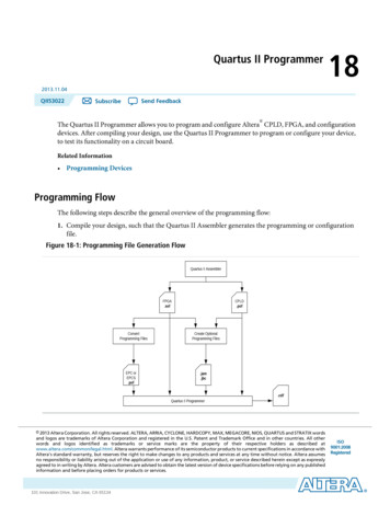
Quartus II Programmer182013.11.04QII53022Send FeedbackSubscribe The Quartus II Programmer allows you to program and configure Altera CPLD, FPGA, and configurationdevices. After compiling your design, use the Quartus II Programmer to program or configure your device,to test its functionality on a circuit board.Related Information Programming DevicesProgramming FlowThe following steps describe the general overview of the programming flow:1. Compile your design, such that the Quartus II Assembler generates the programming or configurationfile.Figure 18-1: Programming File Generation FlowQuartus II AssemblerFPGA.sofConvertProgramming FilesEPC orEPCS.pofCPLD.pofCreate OptionalProgramming Files.jam.jbc.cdfQuartus II Programmer 2013 Altera Corporation. All rights reserved. ALTERA, ARRIA, CYCLONE, HARDCOPY, MAX, MEGACORE, NIOS, QUARTUS and STRATIX wordsand logos are trademarks of Altera Corporation and registered in the U.S. Patent and Trademark Office and in other countries. All otherwords and logos identified as trademarks or service marks are the property of their respective holders as described atwww.altera.com/common/legal.html. Altera warrants performance of its semiconductor products to current specifications in accordance withAltera's standard warranty, but reserves the right to make changes to any products and services at any time without notice. Altera assumesno responsibility or liability arising out of the application or use of any information, product, or service described herein except as expresslyagreed to in writing by Altera. Altera customers are advised to obtain the latest version of device specifications before relying on any publishedinformation and before placing orders for products or services.www.altera.com101 Innovation Drive, San Jose, CA 95134ISO9001:2008Registered
18-2QII530222013.11.04Programming FlowNote: For more information about Chain Description Files (.cdf), refer to About Programming inQuartus II Help.2. Convert the programming or configuration file to target your configuration device and, optionally, createsecondary programming files.The following table lists the programming and configuration file formats supported by Altera FPGAs,CPLDs, and configuration devices.Table 18-1: Programming and Configuration File FormatFile FormatFPGACPLDConfigurationDeviceSerial Configuration DeviceSRAM Object File (.sof)Yes———Programmer Object File (.pof)—YesYesYesJEDEC JESD71 STAPL Format File(.jam)YesYesYes—Jam Byte Code File (.jbc)YesYesYes—3. Program and configure the FPGA, CPLD, or configuration device using the programming or configurationfile with the Quartus II Programmer.Figure 18-2: Programming FlowStartOpen Quartus IIProgrammerHardware setupSelect programming/configuration modeSpecify programming/configuration fileNeed to bypassanother devicein the chain?NoYesAdd device to Quartus IIProgrammerSelect programming/configuration optionsStart operationFinishAltera CorporationQuartus II ProgrammerSend Feedback
QII530222013.11.04Optional Programming or Configuration Files18-3Optional Programming or Configuration FilesThe Quartus II software can generate optional programming or configuration files in various formats thatyou can use with programming tools other than the Quartus II Programmer. When you compile a designin the Quartus II software, the Assembler automatically generates either a .sof or .pof. The Assembler alsoallows you to convert FPGA configuration files to programming files for configuration devices.Related Information About Optional Programming Files AN 425: Using Command-Line Jam STAPL Solution for Device ProgrammingDescribes how to use the .jam and .jbc programming files with the Jam STAPL Player, Jam STAPL ByteCode Player, and the quartus jli command-line executable.Secondary Programming FilesThe Quartus II software generates programming files in various formats for use with different programmingtools.The following table lists the file types generated by the Quartus II software and supported by the Quartus IIProgrammer.Table 18-2: File Types Generated by the Quartus II Software and Supported by the Quartus II ProgrammerFile TypeGenerated by theQuartus II SoftwareSupported by the Quartus esJTAG Indirect Configuration File (.jic)YesYesSerial Vector Format File (.svf)Yes—In System Configuration File (.isc)Yes—Hexadecimal (Intel-Format) Output File (.hexout)Yes—Raw Binary File (.rbf)Yes—Raw Binary File for Partial Reconfiguration (.rbf)Yes—Tabular Text File (.ttf)Yes—Raw Programming Data File (.rpd)Yes—Related Information Generating Secondary Programming FilesQuartus II ProgrammerSend FeedbackAltera Corporation
18-4Quartus II Programmer GUIQII530222013.11.04Quartus II Programmer GUIThe Quartus II Programmer GUI is a window in which you can add your programming and configurationfiles, specify programming options and hardware, and start the programming or configuration of the device.To open the Programmer window, on the Tools menu, click Programmer. As you proceed through theprogramming flow, the Quartus II Message window reports the status of each operation.Related Information Programmer WindowDescribes the Programmer window. Programmer Page (Options Dialog Box)Describes the options in the Tools menu.Editing the Device Details of an Unknown DeviceIf the Quartus II Programmer automatically detects devices with shared JTAG IDs, the Programmer promptsyou to specify the correct device in the JTAG chain.If the Programmer does not prompt you to specify the correct device in the JTAG chain, then you must adda user defined device in the Quartus II software for each unknown device in the JTAG chain and specify theinstruction register length for each device.To edit the device details of an unknown device, follow these steps:1.2.3.4.5.6.Double-click on the unknown device listed under the device column.Click Edit.Change the device Name.Enter the Instruction register Length.Click OK.Save the .cdf.Setting Up Your HardwareThe Quartus II Programmer provides the flexibility to choose a download cable or programming hardware.Before you can program or configure your device, you must have the correct hardware setup.Related Information Setting Up Programming HardwareDescribes the steps to set up your hardware. Setting up Programming Hardware in Quartus II SoftwareDescribes the programming hardware driver installation.Setting the JTAG HardwareThe JTAG server allows the Quartus II Programmer to access the JTAG hardware. You can also access theJTAG download cable or programming hardware connected to a remote computer through the JTAG serverof that computer. With the JTAG server, you can control the programming or configuration of devices fromAltera CorporationQuartus II ProgrammerSend Feedback
QII530222013.11.04Using the JTAG Chain Debugger Tool18-5a single computer through other computers at remote locations. The JTAG server uses the TCP/IPcommunications protocol.Related Information Using the JTAG ServerLists how to use the JTAG ServerUsing the JTAG Chain Debugger ToolThe JTAG Chain Debugger tool allows you to test the JTAG chain integrity and detect intermittent failuresof the JTAG chain. In addition, the tool allows you to shift in JTAG instructions and data through the JTAGinterface and step through the test access port (TAP) controller state machine for debugging purposes. Youaccess the tool from the Tools menu on the main menu of the Quartus II software.Related Information Using the JTAG Chain DebuggerStand-Alone Quartus II ProgrammerAltera offers the free stand-alone Quartus II Programmer, which has the same full functionality as the QuartusII Programmer in the Quartus II software. The stand-alone Quartus II Programmer is useful whenprogramming your devices with another workstation, so you do not need two full licenses. You can downloadthe stand-alone Quartus II Programmer from the Download Center on the Altera website.Related Information Download CenterYou can download the stand-alone Quartus II Programmer from this page.Programming and Configuration ModesThe following table lists the programming and configuration modes supported by Altera devices.Table 18-3: Programming and Configuration ModesConfiguration Mode Supported by theQuartus II ProgrammerFPGACPLDConfigurationDeviceSerial Configuration DeviceJTAGYesYesYes—Passive serial (PS)Yes———Active serial (AS)———YesConfiguration via Protocol (CvP)Yes———In-socket modes (ISM)—Yes (exceptfor MAX IICPLDs)YesYesQuartus II ProgrammerSend FeedbackAltera Corporation
18-6QII530222013.11.04Design Security KeysRelated Information About Programming Configuration via Protocol (CvP) Implementation in Altera FPGAs User GuideDescribes the CvP configuration mode. Programming AdaptersContains a list of programming adapters available for Altera devices.Design Security KeysThe Quartus II Programmer supports the generation of encryption key programming files and encryptedconfiguration files for Altera FPGAs that support the design security feature. You can also use the QuartusII Programmer to program the encryption key into the FPGA.Related Information AN 341: Using the Design Security Feature in Stratix II and Stratix II GX DevicesDescribes how to use the feature in Stratix II and Stratix II GX devices. AN 512: Using the Design Security Feature in Stratix III DevicesDescribes how to use the feature in Stratix III devices.Convert Programming Files Dialog BoxThe Convert Programming Files dialog box in the Programmer allows you to convert programming filesfrom one file format to another. For example, to store the FPGA data in configuration devices, you canconvert the .sof data to another format, such as .pof, .hexout, .rbf, .rpd, or .jic, and then program theconfiguration device.You can also configure multiple devices with an external host, such as a microprocessor or CPLD. Forexample, you can combine multiple .sof files into one .pof.To access the Convert Programming Files dialog box, on the main menu of the Quartus II software, clickFile, and then click Convert Programming Files.Related Information Convert Programming Files Dialog BoxDebugging Your ConfigurationUse the Advanced option in the Convert Programming Files dialog box to debug your configuration. Youmust choose the advanced settings that apply to your Altera device. You can direct the Quartus II softwareto enable or disable an advanced option by turning the option on or off in the Advanced Options dialogbox.When you change settings in the Advanced Options dialog box, the change affects .pof, .jic, .rpd, and .rbffiles.Altera CorporationQuartus II ProgrammerSend Feedback
QII530222013.11.04Debugging Your Configuration18-7The following table lists the Advanced Options settings in more detail.Table 18-4: Advanced Options SettingsOption SettingDisable EPCS ID checkDescriptionFPGA skips the EPCS silicon ID verification.Default setting is unavailable (EPCS ID check isenabled).Applies to the single- and multi-device AS configuration modes on all FPGA devices.Disable AS mode CONF DONE error checkFPGA skips the CONF DONE error check.Default setting is unavailable (AS mode CONF DONEerror check is enabled).Applies to single- and multi-device (AS) configurationmodes on all FPGA devices.The CONF DONE error check is disabled by defaultfor Stratix V, Arria V, and Cyclone V devices for ASPS multi device configuration mode.Program Length Count adjustmentSpecifies the offset you can apply to the computedPLC of the entire bitstream.Default setting is 0. The value must be an integer.Applies to single- and multi-device (AS) configurationmodes on all FPGA devices.Post-chain bitstream pad bytesSpecifies the number of pad bytes appended to theend of an entire bitstream.Default value is set to 0 if the bitstream of the lastdevice is uncompressed. Set to 2 if the bitstream ofthe last device is compressed.Post-device bitstream pad bytesSpecifies the number of pad bytes appended to theend of the bitstream of a device.Default value is 0. No negative integer.Applies to all single-device configuration modes onall FPGA devices.Quartus II ProgrammerSend FeedbackAltera Corporation
18-8QII530222013.11.04Debugging Your ConfigurationOption SettingDescriptionBitslice padding valueSpecifies the padding value used to prepare bitsliceconfiguration bitstreams, such that all bitsliceconfiguration chains simultaneously receive their finalconfiguration data bit.Default value is 1. Valid setting is 0 or 1.Use only in 2, 4, and 8-bit PS configuration mode,when you use an EPC device with the decompressionfeature enabled.Applies to all FPGA devices that support enhancedconfiguration devices.The following table lists the symptoms you may encounter if a configuration fails, and describes the advancedoptions you must use to debug your configuration.Failure Symptoms(2)(1)(3)Disable EPCSID CheckDisable AS PLC SettingsPost-ChainPost-Device Bitslice Padding ValueMode CONFBitstream Pad Bitstream PadDONE ErrorBytesBytesCheckYes(2)—Yes (1)Yes (2)—YesYes (1)Yes (2)—Yes (3)Yes (1)Yes (2)—Configurationfailure occursafter aconfigurationcycle.—YesDecompression feature isenabled.—YesYesEncryptionfeature isenabled.—YesCONF DONEstays low aftera configuration cycle.—YesYesYes(1)Use only for single-device chainUse only for multi-device chainStart with positive offset to the PLC settingsAltera CorporationQuartus II ProgrammerSend Feedback
QII530222013.11.04Failure Symptoms(4)18-9Debugging Your ConfigurationDisable EPCSID CheckDisable AS PLC SettingsPost-ChainPost-Device Bitslice Padding ValueMode CONFBitstream Pad Bitstream PadDONE ErrorBytesBytesCheckCONF DONEgoes highmomentarilyafter aconfigurationcycle.—YesFPGA doesnot enter usermode eventhoughCONF DONEgoes high.——Configurationfailure occursat thebeginning of aconfigurationcycle.YesNewlyintroducedEPCS, such asEPCS128.Failure in .pofgeneration forEPC deviceusing QuartusII ConvertProgrammingFile Utilitywhen thedecompression feature isenabled.Yes(4)————Yes (1)Yes �—YesStart with negative offset to the PLC settingsQuartus II ProgrammerSend FeedbackAltera Corporation
18-10QII530222013.11.04Converting Programming Files for Partial ReconfigurationConverting Programming Files for Partial ReconfigurationThe Convert Programming File dialog box supports the following programming file generation and optionfor Partial Reconfiguration: Partial-Masked SRAM Object File (.pmsf) output file generation, with .msf and .sof as input files. .rbf for Partial Reconfiguration output file generation, with a .pmsf as the input file.Note: The .rbf for Partial Reconfiguration file is only for Partial Reconfiguration. Providing the Enable decompression during Partial Reconfiguration option to enable the option bitfor bitstream decompression during Partial Reconfiguration, when converting a full design .sof to anysupported file type.Related Information Design Planning for Partial ReconfigurationGenerating .pmsf using a .msf and a .sofTo generate the .pmsf in the Convert Programming Files dialog box, follow these steps:1. In the Convert Programming Files dialog box, under the Programming file type field, select PartialMasked SRAM Object File (.pmsf).2. In the File name field, specify the necessary output file name.3. In the Input files to convert field, add necessary input files to convert. You can add only a .msf and .sof.4. Click Generate.Generating .rbf for Partial Reconfiguration Using a .pmsfAfter you have successfully generated the .pmsf, you can convert the .pmsf to a .rbf for Partial Reconfigurationin the Convert Programming Files dialog box.To generate the .rbf for Partial Reconfiguration, follow these steps:1. In the Convert Programming Files dialog box, in the Programming file type field, select Raw BinaryFile for Partial Reconfiguration (.rbf).2. In the File name field, specify the output file name.3. In the Input files to convert field, add input files to convert. You can add only a .pmsf.4. After adding the .pmsf, select the .pmsf and click Properties. The PMSF File Properties dialog boxappears.5. Make your selection either by turning on or turning off the following options: Compression option—This option enables compression on Partial Reconfiguration bitstream. If youturn on this option, then you must turn on the Enable decompression during Partial Reconfigurationoption. Enable SCRUB mode option—The default of this option is based on AND/OR mode. This option isvalid only when Partial Reconfiguration masks in your design are not overlapped vertically. Otherwise,you cannot generate the .rbf for Partial Reconfiguration. Write memory contents option—This option is a workaround for initialized RAM/ROM in a PartialReconfiguration region.Altera CorporationQuartus II ProgrammerSend Feedback
QII530222013.11.04Enable Decompression during Partial Reconfiguration Option18-11For more information about these option, refer to the Design Planning for Partial Reconfiguration.6. Click OK.7. Click Generate.Enable Decompression during Partial Reconfiguration OptionYou can turn on the Enable decompression during Partial Reconfiguration option in the SOF FileProperties: Bitstream Encryption dialog box, which can be accessed from the Convert Programming Filedialog box. This option is available when converting a .sof to any supported programming file types listedin Table 18-2.This option is hidden for other targeted devices that do not support Partial Reconfiguration. To view thisoption in the SOF File Properties: Bitstream Encryption dialog box, the .sof must be targeted on an Alteradevice that supports Partial Reconfiguration.If you turn on the Compression option when generating the .rbf for Partial Reconfiguration, then you mustturn on the Enable decompression during Partial Reconfiguration option.Flash LoadersParallel and serial configuration devices do not support the JTAG interface. However, you can use a flashloader to program configuration devices in-system via the JTAG interface. You can use an FPGA as a bridgebetween the JTAG interface and the configuration device. The Quartus II software supports parallel andserial flash loaders.Related Information About Flash LoadersJTAG Debug Mode for Partial ReconfigurationThe JTAG debug mode allows you to configure Partial Reconfiguration bitstream through the JTAG interface.Use this feature to debug Partial Reconfiguration bitstream and eventually helping you in your PartialReconfiguration design prototyping. This feature is available for internal and external host.During JTAG debug operation, the JTAG command sent from the Quartus II Programmer ignores andoverrides most of the Partial Reconfiguration megafunction interface signals (clk, pr start, double pr,data[], data valid, and data read).Note: The TCK is the main clock source for Partial Reconfiguration megafunction during this operation.You can view the status of Partial Reconfiguration operation in the messages box and the Progress bar inthe Quartus II Programmer. The PR DONE, PR ERROR, and CRC ERROR signals will be monitored duringPartial Reconfiguration operation and reported in the Messages box at the end of the operation.The Quartus II Programmer can detect the number of PR DONE instruction(s) in plain or compressedPartial Reconfiguration bitstream and, therefore, can handle single or double Partial Reconfiguration cycleaccordingly. However, only single Partial Reconfiguration cycle is supported for encrypted PartialReconfiguration bitstream in JTAG debug mode (provided that the specified device is configured with theencrypted base bitstream which contains the Partial Reconfiguration megafunction in the design).Quartus II ProgrammerSend FeedbackAltera Corporation
18-12QII530222013.11.04Configuring Partial Reconfiguration Bitstream in JTAG Debug ModeNote: Configuring an incompatible PR bitstream to the specified device may corrupt your design, includingthe routing path and the Partial Reconfiguration megafunction plac
The Quartus II Programmer supports the generation of encryption key programming files and encrypted configuration files for Altera FPGAs that support the design securi