Transcription
Translation of the original instructionsASM 340Leak detectorMaintenance instructionsEN
Table of contentsTable of contents123About this manual . . . . . . . . . . . . . . . . . . . . . . . . . . . . . . . . . . . . . . . . . . . . . . . 41.1Validity. . . . . . . . . . . . . . . . . . . . . . . . . . . . . . . . . . . . . . . . . . . . . . . . . . . . .1.1.1 Applicable documents . . . . . . . . . . . . . . . . . . . . . . . . . . . . . . . . . . .1.2 Conventions . . . . . . . . . . . . . . . . . . . . . . . . . . . . . . . . . . . . . . . . . . . . . . . .1.2.1 Safety instructions. . . . . . . . . . . . . . . . . . . . . . . . . . . . . . . . . . . . . .1.2.2 Pictographs . . . . . . . . . . . . . . . . . . . . . . . . . . . . . . . . . . . . . . . . . . .1.2.3 Instructions/Abbreviations used . . . . . . . . . . . . . . . . . . . . . . . . . . .1.2.4 Labels . . . . . . . . . . . . . . . . . . . . . . . . . . . . . . . . . . . . . . . . . . . . . . .Safety and maintenance information. . . . . . . . . . . . . . . . . . . . . . . . . . . . . . . .445566672.1Safety precautions . . . . . . . . . . . . . . . . . . . . . . . . . . . . . . . . . . . . . . . . . . . 72.2Protective equipment . . . . . . . . . . . . . . . . . . . . . . . . . . . . . . . . . . . . . . . . . 82.3Maintenance preparation . . . . . . . . . . . . . . . . . . . . . . . . . . . . . . . . . . . . . . 82.4Tools and spare parts . . . . . . . . . . . . . . . . . . . . . . . . . . . . . . . . . . . . . . . . . 9Maintenance intervals and responsibilities . . . . . . . . . . . . . . . . . . . . . . . . . 103.14Calibration . . . . . . . . . . . . . . . . . . . . . . . . . . . . . . . . . . . . . . . . . . . . . . . . . . . . 124.1Purpose. . . . . . . . . . . . . . . . . . . . . . . . . . . . . . . . . . . . . . . . . . . . . . . . . . . 124.2Calibration with the internal calibrated leak . . . . . . . . . . . . . . . . . . . . . . .4.2.1 Internal calibrated leak . . . . . . . . . . . . . . . . . . . . . . . . . . . . . . . . .4.2.2 Procedure . . . . . . . . . . . . . . . . . . . . . . . . . . . . . . . . . . . . . . . . . . .Calibration with an external calibrated leak . . . . . . . . . . . . . . . . . . . . . . .4.3.1 External calibrated leak. . . . . . . . . . . . . . . . . . . . . . . . . . . . . . . . .4.3.2 Adaptor for external calibrated leaks. . . . . . . . . . . . . . . . . . . . . . .4.3.3 Calibration procedure with external leak in Hard Vacuum test . . .4.3.4 Calibration procedure with external leak in sniffing test . . . . . . . .Calibration on concentration (sniffing test mode only) . . . . . . . . . . . . . . .1212121313131414154.5Calibration of a leak detector connected to a pumping unit . . . . . . . . . . .4.5.1 Purpose. . . . . . . . . . . . . . . . . . . . . . . . . . . . . . . . . . . . . . . . . . . . .4.5.2 Target value. . . . . . . . . . . . . . . . . . . . . . . . . . . . . . . . . . . . . . . . . .4.5.3 Procedure . . . . . . . . . . . . . . . . . . . . . . . . . . . . . . . . . . . . . . . . . . .Maintenance / replacement. . . . . . . . . . . . . . . . . . . . . . . . . . . . . . . . . . . . . . .15151515175.1Cleaning the covers . . . . . . . . . . . . . . . . . . . . . . . . . . . . . . . . . . . . . . . . . 175.2Dismantling the covers . . . . . . . . . . . . . . . . . . . . . . . . . . . . . . . . . . . . . . .5.2.1 Dismantling the front cover . . . . . . . . . . . . . . . . . . . . . . . . . . . . . .5.2.2 Dismantling the rear cover . . . . . . . . . . . . . . . . . . . . . . . . . . . . . .Maintenance of the internal calibrated leak . . . . . . . . . . . . . . . . . . . . . . .5.3.1 Replacement . . . . . . . . . . . . . . . . . . . . . . . . . . . . . . . . . . . . . . . . .5.3.2 Recalibration . . . . . . . . . . . . . . . . . . . . . . . . . . . . . . . . . . . . . . . . .5.3.3 Setting . . . . . . . . . . . . . . . . . . . . . . . . . . . . . . . . . . . . . . . . . . . . . .Analyzer cell maintenance . . . . . . . . . . . . . . . . . . . . . . . . . . . . . . . . . . . .5.4.1 Dismantling . . . . . . . . . . . . . . . . . . . . . . . . . . . . . . . . . . . . . . . . . .5.4.2 Seals replacement . . . . . . . . . . . . . . . . . . . . . . . . . . . . . . . . . . . .5.4.3 Filament replacement . . . . . . . . . . . . . . . . . . . . . . . . . . . . . . . . . .Primary pump maintenance (Wet Model) . . . . . . . . . . . . . . . . . . . . . . . . .5.5.1 Localization . . . . . . . . . . . . . . . . . . . . . . . . . . . . . . . . . . . . . . . . . .5.5.2 Oil level check . . . . . . . . . . . . . . . . . . . . . . . . . . . . . . . . . . . . . . . .5.5.3 Oil quality inspection . . . . . . . . . . . . . . . . . . . . . . . . . . . . . . . . . . .5.5.4 Draining the pump. . . . . . . . . . . . . . . . . . . . . . . . . . . . . . . . . . . . .5.5.5 Flushing the pump. . . . . . . . . . . . . . . . . . . . . . . . . . . . . . . . . . . . .5.5.6 Filling the pump. . . . . . . . . . . . . . . . . . . . . . . . . . . . . . . . . . . . . . .5.5.7 Primary pump replacement . . . . . . . . . . . . . . . . . . . . . . . . . . . . . .5.5.8 Replacement of the internal oil mist eliminator . . . . . . . . . . . . . . .5.5.9 Installation of an external mist eliminator . . . . . . . . . . . . . . . . . . .Maintenance of the turbomolecular pump. . . . . . . . . . . . . . . . . . . . . . . . .5.6.1 Localization . . . . . . . . . . . . . . . . . . . . . . . . . . . . . . . . . . . . . . . . . .5.6.2 Access to the fluid reservoir . . . . . . . . . . . . . . . . . . . . . . . . . . . . .4.34.455.35.45.55.62Maintenance time monitoring . . . . . . . . . . . . . . . . . . . . . . . . . . . . . . . . . . 11171718181819192020212123232323232425262727292929
Table of contents5.6.3 Replacing the operating fluid reservoir . . . . . . . . . . . . . . . . . . . . .Pirani gauge maintenance . . . . . . . . . . . . . . . . . . . . . . . . . . . . . . . . . . . .5.7.1 Replacement . . . . . . . . . . . . . . . . . . . . . . . . . . . . . . . . . . . . . . . . .5.8 Maintenance fans . . . . . . . . . . . . . . . . . . . . . . . . . . . . . . . . . . . . . . . . . . .5.8.1 Localization . . . . . . . . . . . . . . . . . . . . . . . . . . . . . . . . . . . . . . . . . .5.8.2 Replacement of the air inlet fan . . . . . . . . . . . . . . . . . . . . . . . . . .5.8.3 Replacement of the turbomolecular pump fan . . . . . . . . . . . . . . .5.8.4 Replacement of the exhaust fan . . . . . . . . . . . . . . . . . . . . . . . . . .5.9 Air filters maintenance . . . . . . . . . . . . . . . . . . . . . . . . . . . . . . . . . . . . . . .5.9.1 Air filters location. . . . . . . . . . . . . . . . . . . . . . . . . . . . . . . . . . . . . .5.9.2 Replacement of air filters no. 1 and no. 2 . . . . . . . . . . . . . . . . . . .5.9.3 Replacement of the vacuum block air filter . . . . . . . . . . . . . . . . . .5.10 Connection the primary pump (Integrable Model). . . . . . . . . . . . . . . . . . .5.10.1 Characteristics of the primary pump . . . . . . . . . . . . . . . . . . . . . . .5.10.2 Connection of the primary pump . . . . . . . . . . . . . . . . . . . . . . . . . .5.10.3 Connection of the primary pump under the frame. . . . . . . . . . . . .Decommissioning . . . . . . . . . . . . . . . . . . . . . . . . . . . . . . . . . . . . . . . . . . . . . g down for longer periods . . . . . . . . . . . . . . . . . . . . . . . . . . . . . . . 386.2Disposal . . . . . . . . . . . . . . . . . . . . . . . . . . . . . . . . . . . . . . . . . . . . . . . . . . 38Malfunctions . . . . . . . . . . . . . . . . . . . . . . . . . . . . . . . . . . . . . . . . . . . . . . . . . . 397.18What happens in case of a defect. . . . . . . . . . . . . . . . . . . . . . . . . . . . . . .7.1.1 Warning fault display . . . . . . . . . . . . . . . . . . . . . . . . . . . . . . . . . . .7.1.2 Warning / fault window . . . . . . . . . . . . . . . . . . . . . . . . . . . . . . . . .7.1.3 List of warnings / faults . . . . . . . . . . . . . . . . . . . . . . . . . . . . . . . . .7.2 Troubleshooting guide . . . . . . . . . . . . . . . . . . . . . . . . . . . . . . . . . . . . . . .7.2.1 Installation of the application. . . . . . . . . . . . . . . . . . . . . . . . . . . . .7.2.2 Consultation of the application . . . . . . . . . . . . . . . . . . . . . . . . . . .Service . . . . . . . . . . . . . . . . . . . . . . . . . . . . . . . . . . . . . . . . . . . . . . . . . . . . . . .9Spare parts . . . . . . . . . . . . . . . . . . . . . . . . . . . . . . . . . . . . . . . . . . . . . . . . . . . . 449.13939394041414143Ordering information . . . . . . . . . . . . . . . . . . . . . . . . . . . . . . . . . . . . . . . . . 443
About this manual1About this manual1.1ValidityThis maintenance manual is intended for the customers of the Pfeiffer Vacuum Company. It describes the product maintenance operations which can be performed by the useron the product concerned. This documentation must be used with the operatingmanual of the product of the same name.The current maintenance manuals are also available on the Internet at www.pfeiffer-vacuum.com.This manual covers products with the following part numbers:1.1.1Part M9AASM 340 Wet (all models)ASM 340 Dry (all models)ASM 340 Integrable (all models)Applicable documentsThe document to be used in reference to this maintenance manual is:4ASM 340Operating InstructionsASM 340 Operating Instructions*also available at www.pfeiffer-vacuum.comP/n 121762 *
About this manual1.2Conventions1.2.1Safety instructionsOperating manual safety instructions Pfeiffer Vacuum are based on the UL, CSA, ANSIZ-535, SEMI S2, ISO 3864 and DIN 4844 certification standards. This document describes the following information and danger levels:DANGERImminent dangerIndicates an imminent hazardous situation that will result in death or serious injury.WARNINGPossibly imminent dangerIndicates an imminent hazardous situation that can result in death or serious injury.CAUTIONPossibly imminent dangerIndicates an imminent hazardous situation that can result in minor or moderate injury.NOTICECommand or noteCommand to perform an action or information about properties, the disregarding ofwhich may result in damage to the product.5
About this manual1.2.2PictographsProhibition of an action or activity in connection with a source of danger,the disregarding of which may result in serious accidentsWarning of a displayed source of danger in connection with operation ofthe unit or equipmentCommand to perform an action or task associated with a source of danger, the disregarding of which may result in serious accidentsImportant information about the product or this document1.2.31.2.4Instructions/Abbreviations used orWork instruction: you must perform an operation here.[XXXX]You must press the XXXX key on the control panel.I/OInputs/Outputs4HeHelium 43HeHelium 3H2HydrogenLabelsIndicates an electrical shock hazard in case of contact: disconnect the electrical power supply before removing the coverand working on the product.Indicates that the operator must: handle the product using the devices shown on this label, comply with the rules for moving the equipment, taking weight anddimensions into account.Locate a grounding point on the product.Product subject to the treatment of waste electronic and electricalequipment in accordance with directive 2002/95/EC.Other labels: see Operating Instructions.6
Safety and maintenance information2Safety and maintenance information2.1Safety precautionsDuty to informEvery person who is involved in maintenance and servicing work on the pump must readand follow the safety-relevant parts of all associated documents.NOTICEExclusion of liabilityPfeiffer Vacuum accepts no responsibility concerning equipment damage, disruptedservice or physical injury resulting from maintenance carried out by technicians whohave not been trained in safety rules (EMC, electrical hazards, chemical pollution). Liability and warranty claims shall be inadmissible in this case.WARNINGRisk of electric shockVoltage and current can cause electric shock. Only skilled, authorised people may carryout maintenance work. Insulate and lock the power supply circuit by positionning the circuit breaker on O Disconnect the power cable from all power sources before any work on the productand/or removing the covers.WARNINGOther located hazardous energiesElectrical circuit and other pressurized circuits as nitrogen are potential hazards: Always lock out these energy sources before working on the product.NOTICEWork/Handling the detectorThe operator must not work on the product to move it or carry out maintenance until ithas come to a complete shutdown! When the circuit breaker is set at O, you must: Unplug the power cable. Wait for the control panel screen to turn off completely before working on the productand/or removing the covers. Wait 5 minutes after switch-off before working on the product. When you order spare parts, you must mention everything featured on the productnameplate. Comply with all safety and risk prevention instructions in accordance with local safetystandards. Regularly check compliance with all precautionary measures. Do not switch on the product if the covers are not in place. To return the product to one of our Pfeiffer Vacuum service centers, read the aftersales Service procedure and complete the declaration of contamination available onour website. Use the original packaging to return the product to a Pfeiffer Vacuum service center:the manufacturer shall not be held liable for any damage resulting from transport inunsuitable packaging.7
Safety and maintenance information2.2Protective equipmentIn some situations, personal protective equipment must be worn when handling the detector and its components. Customers must provide operators with the necessary equipment. This equipment must be checked regularly and used in accordance with the supplier's recommendations.DANGERHealth hazard in case of contact with the operating fluidContact with or inhaling products such as oil from the pump can cause irritation. Wear appropriate protective equipment when carrying out maintenance or adding/draining oil.WARNINGkgRisk of injury through falling objectsWhen transporting parts/items by hand, there is a danger through loads slipping and falling down. Carry small and mid-size parts/items two-handed. Carry parts/items 20 kg with a suitable lifting device. Wear safety shoes with steel toe cap according to directive EN 347.WARNINGRisk of injury through hot surfacesThe products are designed so as not to present a thermal risk for the operator's safety.However, specific operating conditions may exist that require extra caution from usersdue to the high temperatures (surfaces 70 C for parts inside the covers): Leave the part to cool before working on the product. If necessary wear protective gloves according to directive EN 420.CAUTIONRisk of pinchingWhen handling the storage tank cover, there is a risk of fingers becoming pinched.2.3Maintenance preparationNOTICEWork/Handling the detectorThe operator must not work on the product to move it or carry out maintenance until ithas come to a complete shutdown! When the circuit breaker is set at O, you must: Unplug the power cable. Wait for the control panel screen to turn off completely before working on the productand/or removing the covers. Disconnect the detector from the part/installation to be tested: install the blanked-offflange on the detector's inlet (accessory supplied with the product or available uponrequest (see Accessories chapter of the Operating instructions). Handle the detector so it can be moved in the maintenance area (see Handling chapter of the Operating instructions). clean, dust-free and ventilated room, appropriate protective equipment.8
Safety and maintenance information2.4Tools and spare partsThe tools necessary for the maintenance of the detector are available in the maintenancekit supplied with the product. Depending on the maintenance operation, other tools maybe needed, at the customer’s expense.Necessary spare partsReplacement of defective components with parts that are not genuine, jeopardizes theinitial safety conditions of the equipment. Use only spare parts available by asking Pfeiffer Vacuum Service. Ordering information is available in chapter Spare parts. To correctly identify the product when communicating with Pfeiffer Vacuum, alwayshave the information from the product rating plate available.9
Maintenance intervals and responsibilities3Maintenance intervals and responsibilitiesLevel 1 and 2 maintenance operations of the service frequency table are described inthis manual.Level 3 overhaul operations require the intervention of a technician from the Pfeiffer Vacuum Service network.ComponentNumber of hours in useOperationRoutine main- 8,600tenance (3)17,200Level 4)Site (5)OthersPrimary pump RVP 1015 (Model Wet)Oil level and appearance checkxOil changeIIOS4,300 hours (1)IIOSIn case of failureIIIOSIIIOSIn case of failureIIIOSx4,300 hours (1)IIOSxxPump replacement2 AMD1 Primary pumps (Dry Model)Replacement of the diaphragms and valvesxPump replacementPrimary pump (Integrable Model)Refer to the maintenance intervals of the primary pumpconnected to the detectorOil mist eliminator (Wet Model)Oil mist eliminator replacementSplitflow 50 turbomolecular pumpOperating fluid reservoir replacementor 4 yearsIIOSBearings replacementor 4 yearsIIIOSReplacement of the TC 110 frequency converterIn case of failureIIIOSPump replacementIn case of failureIIIOSFilament replacementIn case of failureIOSReplacing the extraction electrodeIn case of failureIIIOSEvery 500,000 testsIIIOSxIOSxIIOSEvery 4,300 hours(recommended)IOSIn case of failureIIOSAnalyzer cellValvesReplacement of all valvesAir filterCleaning or replacement of the air inlet filterAir inlet filterCleaning or replacement of the air inlet filterPirani gaugeSettingxReplacementSmart sniffer probeCapillary filter replacementx(2)IOSSintered filter replacementx(2)IOSx(2)IOSIn case of failureIIOSIOSEvery 2 yearsIIWSEvery 4 years(recommended)IIIOS/WSStandard sniffer probeSintered filter replacementFansFan replacementCleaning or replacement of the fan air filterxCalibrated leakRecalibrationLeak detectorService(1) In case of severe application (with significant flow or contamination)(4) Level:I OperatorII Technical or trained operatorIII Service center10x(2) 160 h In case of severe application (withsignificant flow or contamination)(5) Site:OS On siteWS In Pfeiffer Vacuum service center.(3) Routine maintenance: according to usageconditions
Maintenance intervals and responsibilities3.1Maintenance time monitoringThe cycle counters of the primary pump (Wet and Dry Models)and turbomolecular pumpalert the operator that a maintenance operation must be performed (see MaintenanceMenu of the Operating Instructions).11
Calibration4Calibration4.1PurposeCalibration helps ensure that the leak detector is correctly adjusted to detect the tracergas selected and display the correct leak rate. A calibrated leak is used to calibrate theleak detector.Depending on the test method, different types of calibration can be performed.Test methodHard VacuumSniffingWith the internal calibrated leakyesyes (*)With an external calibrated leakyesyesWith the ambient air (ambient air not contaminated by the noyestracer gas)(*) in this case, the flow of the sniffer probe is not included in the leak detector calibration process.4.2Calibration with the internal calibrated leak4.2.1Internal calibrated leakThe internal calibrated leak is specifically designed for the leak detector. It is composedof: a Helium 4 reservoir (no internal calibration with the other tracer gases),a temperature sensor (to take into account the effect of temperature on the leak rate),an integrated diaphragm (to calibrate the leak rate),an identification label (identical to the identification label of an external calibratedleak).The calibrated leak is supplied with a calibration certificate.4.2.2ProcedureWhen switching the leak detector on, calibration with the internal calibrated leak is automatically initiated if the calibration parameter is set on ’Start-up’ and if the type of calibrated leak is set on ’Internal’.The calibration can begin when the detector is:- in test mode for the hard vacuum test- in test mode or Stand-by for the sniffer test. Check the leak settings (corrected leak rate to take temperature and time into accountif necessary) (see Spectro Menu of the Operating Instructions). Press [Auto cal] key to launch a calibration.In the case of intensive use of the detector, a spare internal calibrated leak is recommended. If this is not possible, the detector can still be used and calibrated using an external calibrated leak.12
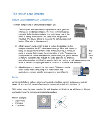
CalibrationNOTICEDetector calibrationWhen switched on, the detector suggests that the operator carry out an auto-calibration(if calibration parameter operator). For the optimal use of the detector, this auto-calibration must be performed. In all situations, a manual or automatic calibration mustbe performed: at least once a dayto optimise the measurement reliability for high sensitivity testsif it is uncertain whether the detector is working properlyduring intense and continuous operation: start an internal calibration at the beginningof each work session (e.g. work in teams, every 8 hours).4.3Calibration with an external calibrated leak4.3.1External calibrated leakThe operator must use a calibrated leak containing the tracer gas selected (4He, 3He orH2). There are several types of external calibrated leaks, with or without reservoir, withor without valve, covering several leak ranges. Use calibrated leaks from the ranges indicated below.GasMinimum ValueMaximum Value4He 1.10-9 mbar·l/s 1·10-10 Pa·m3/s 3·10-7 mbar·l/s 3·10-8 Pa·m3/s 5·10-6 mbar·l/s 5·10-7 ·m3/sThe choice of external calibrated leak depends on the needs of the application:use a calibrated leak from the same leak rate range as the leak to be measured.The manufacturer does not provide calibrated leaks in 3He and H2.4.3.2Adaptor for external calibrated leaksA DN 16 ISO-KF or DN 25 ISO-KF adaptor helps calibrate the detector with an externalcalibrated leak in sniffing test mode (with Standard probe only).Adaptor part numbers (see 9)1432Fig. 1:Adaptor installation Attach the adaptor (1) to the external calibrated leak (2) used for the calibration withcentering ring and a clamp.13
Calibration Start a calibration: press the [Auto cal] function key. Fit the sniffer probe (3) in the calibration opening. Tighten the fixing screw (4). Follow the calibration process indicated on the controlpanel. Loosen the fixing screw (4). Remove the sniffer probe from the calibration opening. Continue the calibration process indicated on the control panel. Wait 10 s (at least) before reading the leak rate.Notes The displayed leak rate takes 4He into account (if 4He used as tracer gas).Example:– calibration with a leak of 2·10-5 mbar·l/s– the displayed leak rate is: 2·10-5 5·10-6 2.5·10-5 mbar·l/s4.3.3Calibration procedure with external leak in Hard Vacuum test Allocate a function key to [Auto.Cal] (see Configuration Menu in the Operating Instructions). Configure the following settings: test method hard Vacuum (see Test Menu) type of calibrated leak external (see Spectro Menu) calibration operator (see Advanced Menu) Check the settings and value of the external calibrated leak used (see SpectroMenu). Correct the temperature, month and year if necessary. Select the tracer gas of the external calibrated leak. Place the external calibrated leak on the detector inlet port. Verify that the detector is on Stand-by mode. Press the [Auto.Cal] function key to start the calibration. Follow the instructions provided by the leak detector: press [Next] to move to the nextstage.At the end of the calibration, the detector returns to Stand-by mode.Recommended procedure when the measuring range differs from the value of theinternal calibrated leak.4.3.4Calibration procedure with external leak in sniffing test Allocate a function key to [Auto.Cal] (see Configuration Menu in the Operating Instructions). Configure the following settings: test method sniffing (see Test Menu) type of calibrated leak external (see Spectro Menu) calibration operator (see Advanced Menu) Check the settings and value of the external calibrated leak used (see SpectroMenu). Correct the temperature, month and year if necessary. Select the tracer gas of the external calibrated leak. Connect the sniffer probe to the detector. Verify that the detector is on Stand-by mode. Press the [Auto.Cal] function key to start the calibration. Follow the instructions provided by the leak detector: press [Next] to move to the nextstage.At the end of the calibration, the detector returns to Stand-by mode.14
Calibration4.4Calibration on concentration (sniffing test mode only)NOTICEBefore launching this function, make sure that the leak detector is in an environment free of tracer gas pollution.Concentration container at atmospheric pressure with a gas mixture of a known 4Heconcentration.Procedure Allocate a function key to [Auto.Cal] (see Configuration Menu in the Operating Instructions). Configure the following settings: test method sniffing (see Test Menu) type of calibrated leak concentration (see Spectro Menu) calibration operator (see Advanced Menu) tracer gas 4He (see Spectro Menu) Connect the sniffer probe to the detector. Verify that the detector is on Stand-by mode. Press the [Auto.Cal] function key to start the calibration. Follow the instructions provided by the leak detector: press [Next] to move to the nextstage.At the end of the calibration, the detector returns to Stand-by mode.4.5Calibration of a leak detector connected to a pumping unit4.5.1PurposeWhen the leak detector is connected to an installation equipped with its own pumpingunit, only part of the leak will be analyzed by the leak detector. Calibration helps obtaina direct reading of the leak rate by taking into account the loss of tracer gas of the leakpumped by the pumping unit.Calibration is performed via the Correction function.4.5.2Target value3 possible target values:Target value Hard VacuumSniffingExternal calibrated leak value (1) Tracer gas concentration of a container filled with a known gas mixture including the tracer gasAmbient air (be careful with the tracer gas concentra tion: no tracer gas pollution)(1) When an external calibrated leak is used, it is recommended to take into account the calibration dateand temperature effect for calculating the target value from the calibrated leak value featured on itsidentification label. Corrected leak rate target value measured leak value x correction factor. Background corrected leak rate background measured leak rate x correction factor.4.5.3ProcedureCalibration must only be performed when the leak detector is already calibrated on theinternal calibrated leak.NoteThe correction must be made using the same test method as that used by the operator. If the operator works using both test methods (Hard Vacuum and sniffing),he/she must make a correction for each method.15
Calibration Allocate a [Correction] function key (see Configuration Menu in the Operating Instructions). Select the 'Hard Vacuum' or 'sniffing' test mode. If ’Sniffing test’, connect the sniffer probe to the detector: connect it to an externalcalibrated leak or place it in a container with a known concentration. Pressto start a test. Press the [Correction] function key. if the value of the correction factor to be applied is known:– Press [Value] and configure the correction factor to be applied. The correction factor is the coefficient to be applied to the measured leak rate.– Press [Return] to exit the function. if the value of the target leak rate is known (value of the internal/external calibratedleak or concentration):– Press [AutoCal] [Target] and configure the target leak rate.– Press [Run] to make the correction.– Press [Return] to exit the function. Press [Reset] to reset the correction factor to 1.The ’COR’ indicator light (see Standard screen of the Operating Instructions, ref. 9) isilluminated on the control panel as soon as the value of the correction factor is not 1.The digital display takes into account the correction factor applied.The bargraph display does not take into account the correction factor applied.16
Maintenance / replacement5Maintenance / replacement5.1Cleaning the covers Clean the covers using a lint-free cloth and a product which does not damage printedsurfaces and self-adhesive labels.5.2Dismantling the coversTools5.2.1 5 mm Allen key supplied in the maintenance kitDismantling the front cover Shut down the detector (Position the circuit breakeron O, control panel switchedoff and mains power cable disconnected). Install the blanked-off flange on the detector's inlet port. Remove the black flange around the inlet port. Lift the lid of the storage tank: loosen and remove the 2 upper fixing screws. Loosen and remove the 2 side fixing screws.Fig. 2:Location of the front cover dismantling screw Remove the front cover and extricate it from the detector (1.5 mm max) (see 5.2.1). On the supervisor board, disconnect the connector from the control panel to fully release the cover.Fig. 3:Disassembly of the front cover17
Maintenance / replacement5.2.2Dismantling the rear cover Remove the front cover (see 5.2.1). Disconnect the primary external pump if it is connected to the back of the detector. Donot leave the clamp on the pipe connection (5). Loosen and remove the 5 fixing screws (1), (2) and their washers
4He Helium 4 3He Helium 3 H2 Hydrogen Indicates an electrical shock hazard in case of contact: disconnect the electrical power supply before removing the cover and working on the product. Indicates that the operator must: handle the product using the devices shown on this label, comply with the rules for moving the equipment, taking weight and