Transcription
Hi everyone, my name is Michał Iwanicki. I’m an engine programmer at Naughty Dogand this talk is entitled: “Lighting technology of The Last of Us”, but I should havecalled it “old lightmaps – new tricks”1
The Last Of Us is an action-adventure, survival-horror game, with a heavy emphasison story and characters. It takes place in the near future, where mankind has beendecimated by a mind-controlling fungus. If you haven’t seen the game yet, here’s ashort trailer 2
Since the game takes place in a post-apocalyptic world, there’s almost no electricity,so no artificial light sources. The majority of the lighting comes from the sun and thesky, so most of the environments are lit just by bounce lighting.There was a very strong art direction: we wanted to show the beauty of this lighting,its softness, how it interacts with different surfaces, the soft shadows it creates. Wewanted to show specular highlights of the indirect illumination and show all thosesubtle details modeled with normal maps.3
Just to give you an overview of what we were after, here’s some concept art 4
5
As you can see, all the lighting is very soft, but you still get a very clear read of all thesurface details.6
From the very beginning, we knew that to achieve this level of quality, relying purelyon runtime lighting would not be enough. We knew that we had to compute ourlighting offline, so we decided to use lightmaps.The problem with lightmaps is that even though the game industry has been usingthem for years now (since Quake 1?), they still suffer from really fundamental issues 7
Like the seams: the discontinuities in the lighting.It can happen that parts of the mesh that are contiguous in 3D space are mapped intodisjoint regions in UV space, and the interpolated lighting values along split edgesdon’t quite match, which causes visible seams.While methods to deal with this do exist, they either generate additional cost atruntime or impose restrictions on shape and/or placement of charts in uv space,leading to inefficiencies in the uv space usage, which we wanted to avoid.Seamless atlasing methods can be used but with the size of our levels, they were toocostly to integrate into our pipeline.8
We found a pretty simple, yet effective solution: if the interpolated values on bothsides of split edges don’t match, let’s just make them match, by slightly modifying theintensities of the surrounding texels.9
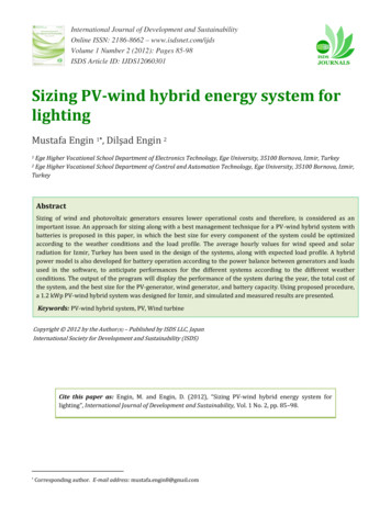
Let’s take a look at the example: a mesh in 3D space is atlased into 2 disjoint regionsin UV space. Along the split edge we create a number of “stitching points” (we createthree points per texel, since the bilinear interpolation follows a quadratic curve).Let’s examine one of those stitching points. The value in the stitching point for thechart on the left, Ci0, is the interpolated value of four surrounding texels, marked inblue.Same with the value on the other side of the edge: Ci1.We want Ci0 and Ci1 to be equal.We can define the error for this stitching point as a squared difference betweenthem.And then we define the error function for the whole lightmap, which is the sum ofthe errors for individual stitching points.10
Once we have the error function we simply minimize it using least squares, treatingtexel values as variables. The optimization modifies the texel values slightly andmakes sure that the total error is minimized. To make sure that the values don’tdeviate from the originally calculated ones, we add additional constraints thatpenalize deviation from the calculated values, with a user-controllable strength.It works surprisingly well: it doesn’t require any changes to the UV layout and doesn’tgenerate any additional cost at runtime; it can be easily applied to already existingmaps.This isn’t limited to lightmaps: the method can be used on other types of maps aswell.11
There are some caveats however. First of all: block compression, which tends to breakthe stitching a bit. In most cases it still looks ok, but when it doesn’t we have anoption to re-stitch the compressed texture, this time modifying blocks’ anchor pointsinstead of individual pixels.The second thing is the linear solver: just don’t write your own, it’s just a bad idea.There are some pretty good ones available, and if you don’t like the hassle ofintegrating big libraries, there’s Eigen which is all template based and comes as acollection of header files.12
This is one, small off-topic slide, but I just couldn’t resist: just add least-squaresminimization to your bag of tricks. It’s really useful but often overlooked by the gamedevelopers community. Once you use it, you suddenly see tons of other applications.On of them is the pipeline for 3D LUTs used for color corrections in games:The workflow usually looks like this:- Take screenshot- Embed identity volume texture in the image- Massage in Photoshop- Extract LUT- Then in game, you render your scene, take the extracted LUT, apply it and you getthe same result as in PhotoshopWell, the problem is that it’s not the same. Due to quantization of variouscomponents, you can get pretty serious discolorations.What we do: we minimize the difference between the image from Photoshop and theimage in game. The error function is defined as a squared difference between thosetwo images, and we modify the volume texture so that it’s minimized.It works much better than just using the straight volume texture.13
But going back to lighting We wanted to avoid the flat look of our surfaces in the absence of direct lighting, sowe knew that we needed some sort of directional information in the lightmaps.We evaluated different options, like the HL2 basis and spherical harmonic lightmaps,but we settled on a very simple representation: a pair of ambient and directionallights stored for every lightmap texel.14
Why? It has some really nice properties:1. It’s very easy to understand by the artists, which is extremely useful, since they likeinvestigating the outputs from the bake process2. It can be hand tweaked to some extent3. And we have the direction of the dominant light, which we can also use to getsome additional effects.15
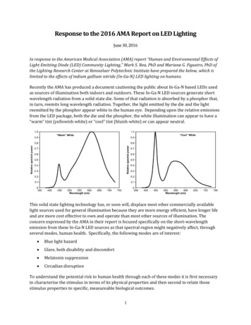
For each texel of our lightmap, the baking tool generates some distribution ofincoming lighting, and we divide is into two components:- Ambient term: which is just a single color, intensity of the uniform lighting arrivingfrom all directions- Directional term: which is a direction vector and a color – intensity of lightingarriving from that directionWe generate this representation from an SH lightmap generated by our globalillumination bake tool.We do it in a way that minimizes the difference in the final lighting produced by thosetwo representations.16
With this representation, we can use normal maps to provide high frequency details.The intensity of the diffuse lighting is simply: ambient term directional color * (n.l)For glossy surfaces we also use that direction to add a specular highlight.17
And this is all great, but then we add characters 18
19
EEEE, wrong!The character looks as if he was a sticker slapped on top of the screen.20
We want this! Where character properly interacts with the lighting, is nicelygrounded, casts a believable shadow. He actually looks like it’s part of theenvironment, not something added later on.21
The origianal inspiration came from SH exponentiation papers. They approximateoccluders with sets of spheres and combine visibility functions described as SHvectors, by multiplying them together in a fancy way.The problem is that to get long shadows, you need a high SH order. 2nd order SHworks fine for AO – Stephen Hill did something similar in Splinter Cell Conviction – butfor shadows it’s just not enough.22
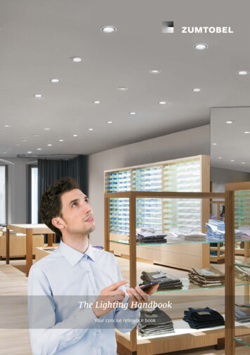
BUT! Our representation of lighting comes to the rescue. It has a very simplestructure: it’s just an ambient component and a directional component. We don’tneed to worry about the whole visibility function, we just need to occlude those twoparts appropriately.Just like the papers mentioned, we approximate the occluders with spheres. Then, forevery point we shade, for each of those occluding spheres:- For the ambient component, we compute the occlusion of the as a cosineweighted percentage of hemisphere occluded by the sphere- For the directional component we trace a cone from a point being shaded, in thedirection of the dominant lighting and check for the intersections with theoccluder sphere23
Here’s the breakdown of how it works:We have some lighting at a point in space and a occluder and how the occlusionvalues are calculated for both components24
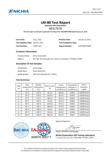
This is how it works in practice – first without, then with the occlusion calculations.25
Now some technical details:For the ambient component, there’s a closed form solution for the occlusion value:it’s just the cosine lobe integrated over the solid angle subtended by the spheredivided the cosine lobe integrated over the entire hemisphere.There is a formula to calculate the occlusion of the directional component as well,but it’s rather cumbersome. We’ve found that it’s much easier to just precompute itusing Monte Carlo methods and store it in a texture. For a given cone angle, theocclusion value is a function of the angle subtended by the occluder (theta) and theangle between the cone axis and the vector pointing towards the occluder center(phi). We can store this function in a 2D texture, and for different cone angles we canstack several of them in a 3D texture.26
The angle of the cone we use for tracing is chosen arbitrarily. It controls thepenumbra size, and we exposed it to our artists. They can change it on per-level basis,but there’s nothing to prevent using different angles for every pixel on the screen.27
We accumulate the results of both intersection tests for individual spheres, bymultiplying results. This is not 100% accurate and in theory can cause doubleocclusion, but it’s not visible in practice (I don’t see it even though I know what tolook for).28
Here are some more low-level detail details:We do all the intersection tests on the SPU. We start by rendering the dominantdirection into a offscreen buffer. It is passed to the SPUs together with thedescriptions of the occluders.SPUs divide the image into tiles and check which occluders influence each tile. Eachoccluder has a “sphere of influence” – so it casts shadows only inside that sphere –and we check if those spheres of influence intersect our tiles. It’s pretty similar tohow you do culling of lights for tiled deferred lighting. One problem is that the tilesare pretty small compared to the size of the spheres, and if you cull using typicalfrustum-sphere intersection test you get a lot of false positives. We eliminate them bycalculating the view space bounding box of the pixels within a tile and testing this boxagainst the sphere of influence, which is a much tighter test.Once we have the list of occluders influencing the tile, we compute the occlusion forambient and directional components, accumulate the results for individual spheresand write out the results to a texture.This texture is used by the GPU in the main rendering pass to attenuate the lightingfetched from the lightmap.29
For 4-5 characters on screen it takes around 6-7ms, but it’s split onto 6 SPUs, so theresults are ready in less than 2ms, and the GPU is doing some other stuff in themeantime anyway, so it doesn’t wait for the SPUs.30
A few more tricks to get better performance:We introduced the ellipsoid as an occluder too – it’s just a sphere scaled along oneaxis. When we test for the intersections, we transform the cone to the space of theellipsoid and scale it down along the main axis, so the ellipsoid becomes a sphere.The direction of the cone is scaled as well, but we don’t change the cone angle. Weshould squash it along the scaling axis, but it would cause it to become non-radiallysymmetric, which would make the intersection test more complicated. We leave it asis and perform the intersection as before.This is not accurate, but looks good and saves us a lot of performance, since we cangreatly reduce the number of spheres we use.31
The whole effect is rendered in ¼ resolution, but due to the low-frequency nature ofthose shadows, it works really well.Most objects use the result texture as is, just upscaling. We added bilateral upsampleas an option for some of the objects, but it’s used very sparingly, since it’s a bit toocostly for us.32
For the objects that would require too many spheres to approximate, we also supportprecomputing occlusion information and storing it in a 3D texture. We store anaverage, unoccluded direction and the spread of the occluded direction. With thissetup, the intersection test becomes a cone-cone intersection (which in fact is thesame as cone-sphere, so we use the same lookup texture for this).The occlusion fromthose objects is composited on top of the regular ones.33
To conclude: precomputed lighting is definitely not dead yet. With some relativelysimple tricks you can make it look much better.Don’t forget about least-squares minimization, and don’t write your own linear solverfor it!34
Here are some references35
Thanks for your attention. If you have any questions now I’ll be more than happy toanswer them!36
37
38
39
40
The Last Of Us is an action-adventure, survival-horror game, with a heavy emphasis on story and characters. It takes place in the near future, where mankind has been decimated by a mind-controlling fungus. If you haven’t seen the game yet, here’s a short trailer 2 . Since the game takes place in a post-apocalyptic world, there’s almost no electricity, so no artificial light sources .