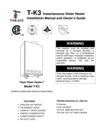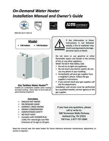
Transcription
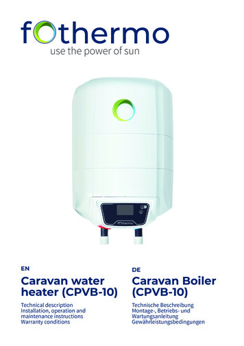
ENCaravan waterheater (CPVB-10)Technical descriptionInstallation, operation andmaintenance instructionsWarranty conditionsDECaravan Boiler(CPVB-10)Technische BeschreibungMontage-, Betriebs- undWartungsanleitungGewährleistungsbedingungen
Table of Contents /InhaltsverzeichnisSpecifications / SpezifikationenEN – USER MANUALAssemblyWater connectionDrainageCurrent sourceSettings – User interfaceFurther informationGeneral WarningsSafety InstructionsFurther important NotesTechnical DataAssemblyConnection to the water supplyElectrical ConnectionMaintenanceMalfunctionEnvironmental ProtectionWarrantyDE – gStromquelleEinstellungen – BenutzeroberflächeWeitere InformationenAllgemeine WarnhinweiseSicherheitshinweiseWeitere wichtige HinweiseTechnische DatenMontageAnschluss an die WasserleitungElektrischer AnschlussWartung und 16171719202020212121222324252525IMPORTANT!fothermo System AGBeim Mühlbach 389171 IllerkirchbergGermanyPlease read these operating instructions carefullybefore installing and commissioning the hot watertank!Phone: 49 (0)1520 439 058 9Email: contact@fothermo.comRegistergericht Ulm: HRB 739609VAT: DE329022123Bitte lesen Sie diese Bedienungsanleitung vorMontage und Inbetriebnahme des Warmwasserspeichers sorgfältig durch!WICHTIG!2
EN / DESpecifications / SpezifikationenSpecifications / SpezifikationenUnit / EinheitValue / WertWater Heater / BoilerProduct name / ProduktmodellCPVB-10Volume / Volumenl9.5A Energy efficiency class / EnergieeffizienzklasseRated pressure / NenndruckMPa0.7X1IP Class / IP-SchutzklasseGross weight ( 3 %) / Gewicht ( 3 %)kg8Max. water temperature / Max. Wassertemperatur C65Boiler dimensions (length, width, height) /Boilermaße (Länge, Breite, Höhe)cm40 x 30 x 33min. installation dimensions (length, width, height)/min. Einbaumaße (Länge, Breite, Höhe)cm53,5 x 30 x 33Integrated MPP Tracker / Integrierter MPP TrackerIntegrated reverse polarity protection /Integrierter VerpolungsschutzDigital display / Digitales DisplayBoiler made of steel with enamel coating /Boiler aus Stahl mit EmaillebeschichtungWater connection / WasseranschlussG½ (M)Combined check and pressure relief valve /Kombiniertes Rückschlag- und ÜberdruckventilInput / AnschlussMax. Voltage (UOC) / Max. SpannungVDC42.4Max. current consumption / Max. StromaufnahmeA15.5Energiebedarf (Heizvorgang von 15 C auf 65 C) /Energy requirement (heating process from 15 C to 65 C)Wh580Max. heating power / Max. HeizleistungW550Recommended photovoltaic power /Empfohlene PhotovoltaikleistungWᵖ150 – 300Max. connected photovoltaic power /Max. anschließbare PhotovoltaikleistungWᵖ15003
USER MANUAL – ENAssemblyThe caravan boiler must be mounted on a solid base plate with fourscrews. Use suitable screws or other mounting systems for your baseplate. Optionally, the boiler can also be mounted vertically on a stablewall.1.2.3.4.How was it measured?Horizontal and vertical installation of thephotovoltaic boiler is possible.The boiler was heated up to 65 C. It was drainedat about 5 litres per minute. From a water temperature at the shower head of 35 C until the waterwas 35 C again, the volume was measured.Advantages of vertical installation Relatively low heat losses 8 litres of hot waterAdvantages of horizontal installation Slightly more heat loss 9.5 litres of hot water4
ENWater connectionFor safety reasons, the non-return/overpressure valve supplied mustbe connected to the cold water inlet of the boiler.The supplied drain plug must be connected to enable draining. Thiscan be done using the T-piece provided, as shown in Figure 1.We recommend integrating the caravan boiler into a water system asshown in figure 2.312412Figure 1Figure 251 Valve T-piece to be able to drain the boiler2 Non-return / pressure relief valve3 Water tank e.g. 40 litres4 12 V pump (lying in the water if necessary).Recommended pressure min. 0,75 bar5 Dusche / Waschbecken5
ENDrainageThe water in the boiler must not freeze. Frozenwater in the boiler can cause damage or a defectin the appliance. If necessary, the contents of theboiler can be drained via the non-return/overpressure valve and the drain plug. Proceed as follows: Open the drain plug using the vent key provided. Tilt the small lever of the check/relief valve 90 . The water should now drain away. Drainage iscomplete when no more water comes out ofthe valves. Ensure that any water that leaks from thenon-return/overpressure valve and the drainplug can drain away safely. This is important toprevent possible water damage. Small amounts of water remain in the boilereven after emptying. This is fine and does notcause any damage. Disconnect the water heater from any liveelectrical wiring. Shut off the cold water supply.The draining water can be hot - risk of scalding!These steps do not ensure complete emptying of the water tank.Current sourceConnect the power supply only when the water heater is filled.Usable Energy SourcesSourceVoltageTypePV module0 VOC – 42.4 VOC–Battery12 V, 24 VLead acid, LiFePO4External energy management12 V – 42.4 V–When connecting several photovoltaic modules,these must only be connected in parallel.6
ENHeating times depending on the input power and sourceSourcePV modulePowerTemperature increase / hour100 W9 C / h300 W27 C / h550 W47 C / h12 V (ca. 90 W)max. 8 C / h24 V (ca. 350 W)max. 32 C / hBattery7
ENSettings – User interfaceBriefly pressing thebutton takes you to the next optionpage (see figure 1).A long press turns the boiler on or off.Figure 1To change possible settings on an option page, such asthe minimum temperature or the operating mode, brieflypress thebutton (see figure 2).Figure 2Option pages at a glanceNrInformation / Input option1Shows the water temperature in C.2POWER IN: Shows the instantaneous power consumption of the boiler.VOLTAGE: Shows the current supply voltage of the boiler.3USED PV ENERGY: Displays the total PV energy consumed by the boiler.4CHANGE MIN. TEMPERATURE: With thebutton you can change the minimum temperature.This option interface is not available in all operating modes (see operating modes).5CHANGE SYSTEM MODE: You can use the6Shows the boiler type and the version numbers of the electronics and software.button to change the operating mode.8
ENSelect operating modeModesEnergy sourceDescription1: PV HomePV module/External energymanagementThe boiler is heated with photovoltaic electricity. This modeshould be selected if there is an external energy management(e.g. solar charge controller with deep discharge protection)which releases the power for the boiler.2: 12 V Battery12 V BatteryAs soon as the battery reaches a voltage of 13.5 V during thecharging process, the excess energy is used to heat up theboiler.3: 12 V BatteryReheat12 V BatteryIn addition to the excess control as in mode 2, the water is alsoheated to this temperature again as soon as the set minimumtemperature is undershot. (But only until the maximum batteryvoltage of 12.4 V is reached.)4: 24 V Battery24 V BatteryAs soon as the battery reaches a voltage of 27.0 V during thecharging process, the excess energy is used to heat up theboiler.5: 24 V BatteryReheat24 V BatteryIn addition to the excess control as in mode 5, the water is alsoheated up to this temperature again as soon as the set minimum temperature is undershot. (But only until the maximumbattery voltage of 24.8 V is reached.)Further informationGeneral WarningsSafety InstructionsBe sure to carefully read the instructions and warnings in this manual before installing and operatingthe water heater. The information contained in thismanual is intended to familiarize you with the waterheater, the rules of its correct and safe operation,and the minimum requirements for its maintenanceand servicing. Furthermore, you are obliged to makethis manual available to the qualified personnel whowill install and potentially repair the appliance. Theinstallation of the water heater and the verificationof its functionality is not within the distributor'swarranty obligation nor the manufacturer.These instructions should always be kept near theappliance for future reference. Compliance with therules here described is part of the measures for thesafe use of the product and is considered part of thewarranty conditions.WARNING! There is a risk of burns or scalding when9using the appliance!WARNING! This device can be used by childrenfrom the age of eight and also by people with a lackof experience and knowledge or reduced physical,sensory or mental abilities, if they are supervised orhave been instructed in the safe use of the deviceand understand the resulting dangers. Childrenmust not play with the device. Cleaning and usermaintenance shall not be made by children withoutsupervision.IMPORTANT! Only qualified personnel may installthe water heater and connect it to the water pipefollowing the specifications given in this manual andthe relevant local regulations. The protective devicesprovided or recommended by the manufacturer, aswell as all other assemblies, are UNCONDITIONALLYto be installed!
ENIMPORTANT! Be sure to fill the water heater withwater before connecting it to the electrical supply! Failure to comply with the electrical connection conditions affects the safety of the appliance,whereby the water heater must not be operated.IMPORTANT! Observe the maximum permissiblepressure (see chapter: Technical data).Further important notes The device is under pressure. Expansion watermay drip out of the pressure relief valve duringheating.vice water, in particular: chloride content up to 250mg/l; electrical conductivity more than 100 µS/cm,pH value 6.5 - 8 for hot water tanks with enamelledwater tank. The thermal insulation consists of CFCfree polyurethane foam.The maximum electrical output of the hot water storage tank is 550 W. The actual output of the heatingelements depends on both the connected photovoltaic output and the intensity of the sun's radiation.The water is heated to a maximum of 65 C to ensureprotection against scalding. Detailed informationcan be found on the data sheet or the nameplate.The hot water storage tanks are equipped with acombined non-return and pressure relief valve,which prevents the water from being over-pressurized while the device is in operation. The watertanks are made of steel with a high-strength enamelcoating and additional cathodic protection with amagnesium anode. Operate the pressure relief valve regularly toprevent it from getting stuck, e.g. B. to preventlimescale deposits. Install a type-tested pressure relief valve in thecold water supply line. Note that dependingon the pressure of the supply line, a pressurereducer may also be required.Assembly Attach a drain line to the opening of the reliefvalve, with an even slope to the drain.Always install the water heater lying down, in a dryenvironment. The device is intended for fixed floorassembly as well as for the wall. Make sure that theassembly surface is sufficiently stable to withstandforces that act on the boiler or its mounting systemwhen driving. When choosing a suitable substratefor the hot water storage tank, the following mustbe taken into account: Dimension the drain line so that the water candrain unhindered when the overpressure valveis fully open. The opening of the pressure relief valve mustnot be blocked. This device contains rechargeable batterieswhich are not replaceable. However, their defect does not limit the basic functionality. Type and material The device may be operated up to an altitude of4000 m above sea level. Type of fastening Dimensions of the device, The device owner is responsible for preventingpossible damage due to lightning strikes andfor proper installation of the PV modules withlightning protection. Location of fasteners for floor mounting Arrangement of water and electricity lines Degree of protection against water splashesTechnical dataThis water heater can provide hot water from themains water supply or other pressure-operatedwater supply for several consumers at the sametime. The water used for heating must meet therequirements of the normative documents for ser-10The installation site must comply with the requirements of the water and electrical installation.Sufficient space for the water connections must beprovided during installation.The boiler is bolted to the floor or the wall using theattached mounting rails. Four screws are used forthis. The type, length and diameter of the screws
ENmust be selected according to the nature of the floor.Only with the right screws is it possible to safelyinstall the boiler.of the steps to be performed is:Connection to the water supply Wait until the air has escaped from the systemand a strong jet of water flows out of the tapping point. Run water for about 30 seconds.When connecting the device to the water pipe, please note the arrows and the information rings aroundthe cold and hot water pipes (supply and returnpipe). The cold water pipe has a blue ring and ismarked with an arrow pointing to the pipe. An arrowaway from the pipe and a red ring indicate the hotwater pipe. The hot water tank is equipped with acombined non-return and pressure relief valve. Thisis included in the product packaging and MUST beinstalled on the cold water line. During this installation, the arrow on the body of the valve indicatingthe direction of water flow through the valve mustbe followed.The pipe connections have G½ external threads.Schematic representations regarding the connectionof the hot water tank are shown in Figures 1 and 2.The hot water tank works with the pressure of thewater pipe. The water pressure in the water supplysystem should be higher than 0.1 MPa (1 bar) andlower than 0.5 MPa (5 bar). If the water pipe pressureis higher than 0.5 MPa, a pressure reducing valvemust be installed.If additional accessories that are not included inthe scope of delivery must be used in accordancewith local regulations, these must be installed inaccordance with the specifications. In case the watersupply pipes are made of copper or other metal,which is different from the metal of the water tank,as well as when brass fasteners are used, non-metalfittings should be mounted on the inlet and returnsides of the water heater (dielectric fittings ).WARNING! It is forbidden to install any shut-off ornon-return fittings between the combined valve andthe hot water tank, as well as blocking the side opening of the combined valve and/or locking its lever!A drainage system to evacuate the contents of theboiler or possible dripping water from the sideopening of the combined valve must be provided.The drain line must be designed with a constantgradient. It must always remain open. After the hotwater tank has been connected to the water pipe,the water tank must be filled with water. The order11 Fully open the hot water tap at the furthestpoint of use. Close the hot water tap at the extraction point. Lift the small pressure relief valve lever (Table1, item 5) for 10 seconds. A strong jet of watermust flow out of the lateral opening of thevalve. Release valve lifting.WARNING! If no water flows out of the valve ope-ning or only a thin stream flows, then this indicatesa malfunction. There may be contamination in thewater line. The error must be rectified before commissioning.WARNING! The combined non-return and pres-sure relief valve is one of the protective devices thatensure the safety of the hot water tank. It is strictlyFORBIDDEN to use the water heater with a damagedor removed/not installed combined non-return andpressure relief valve (safety valve)!IMPORTANT! In Denmark, Sweden, Norway andFinland, the hot water tank may only be connectedto the public water network using a suitable pressurereducing valve. Local regulations must be observed.Electrical ConnectionWARNING! Any electrical connection may only beperformed when the water heater is filled with water.IMPORTANT! The water heater is powered by di-rect current. The water heater is protected againstelectric shock "class ІII" and may only be suppliedwith safety extra-low voltage (SELV). Only powersources recommended by the manufacturer maybe connected. A faulty and/or unsuitable powersupply involves a high risk and is likely to cause anaccident. The connection cables of the device mustbe replaced if they are damaged.IMPORTANT! Photovoltaic modules may ONLYbe connected in parallel. When connecting more
ENthan one photovoltaic module, always use a suitable connector for parallel connection. For moreinformation, refer to the illustration "Parallel PVConnector". Connecting photovoltaic modules inseries will damage the water heater.42.4 V. Photovoltaic modules must be properly connected to the connection cable.Dimensioning of the required photovoltaic power: The higher the expected number of hours ofsunshine per day of use, the lower the requiredPV power.ParallelPV-Connector The warmer the water supplied from the pipe,the smaller the required PV power. The higher the amount of hot water requiredper day, the greater the required PV power.The following table serves as a guideline for dimensioning the photovoltaic power needed dependingon the climatic conditions:Connection of PV-modules in parallel configurationonly! Serial connection will damage the unit!Climatic conditionsThe electrical connection to the hot water boiler ismade via the connection cable. After completingthe electrical connection, be sure to check the functionality of the device. The wires of the connectioncable are numbered and should be connected to thepower source as follows: Wire numbered “1” to the positive pole of thesourceCPVB-10Sun-poor countriese.g. Northern and Central Europe300 WᵖSunny countriese.g. Southern Europe and Africa150 WᵖThe values shown are guide values. Depending on thelocal conditions and the respective usage conditions,the sensible design of the photovoltaic output candeviate from the values described. Wire numbered “2” to the negative pole of thesourceConnection of the PV modulesIMPORTANT! The installation and electrical par-allel connection of PV modules may only be carriedout by a qualified person and may not endangerthird parties. When installing the photovoltaic modules, the locally prevailing rules and laws must becomplied with.IMPORTANT! Always lay cables in such a way thatnobody can trip over them or get caught on them.There is a risk of injury. The cables must be fixed insuch a way that there is no strain on the connectors.Furthermore, it must be ruled out that the cables andconnectors rub against surfaces and edges (e.g. inthe wind) or are permanently in the water.IMPORTANT! All photovoltaic modules may be opera-ted with a maximum open circuit voltage (VOC) of12Extension of the photovoltaic lineIf the photovoltaic cable is extended, the MC4 contact plugs must be properly fastened to ensure functionality and safety. Basically, the PV cable should bekept as short as possible. A length recommendationdepending on the connected PV generator nominalpower can be found in the table below.Recommendation of the cable dimensioningcrosssectionLength(back andforth)2,5 mm²4 mm²6 mm² 6m 10 m 10 m
ENOTHER IMPORTANT NOTESWater leakage: The non-return and pressure re-lief valve can drip during normal operation of thewater heater due to the expansion of water duringheating. Make sure that escaping water can alwaysdrain away. The dripping of water is not a defect. Thelateral valve opening must not be closed in any way.Noise development: Noise may develop insidethe device while water is being heated. This is dueto calcareous deposits on the heating element.Increased limescale formation can be seen fromwater temperatures of over 60 C. This can lead toimpairment and damage to the heating elementsand the hot water tank.Legionella formation: Due to the small volumeof the hot water storage tank, the risk of legionellaformation in the system can be almost completelyruled out. In order to take precautionary measures,however, the following measures are recommended: Supply of fresh water or regular water withdrawal. The water is heated at regular intervals to atleast 60 C. If the device has not been used for more than amonth, a water change is recommended.facturer and dealer. Regular cleaning of the watertank from accumulated limestone is recommendedfor safe operation. This cleaning should be done atleast once every two years. When operating withcalcareous water more often. The deposits on theenamel coating must not be scraped off, just wipedwith a dry cotton cloth. Regular cleaning and removal of limescale is particularly important for thesafe operation of the device. It is advisable to checkthe anode of the enamelled water tank at the sametime. These services are not part of the warrantyand must be carried out by competent persons. Theregulations for checking the anode protection andreplacing the anode and removing the collectedscale must be observed both during and after thewarranty period of the device.Pressure relief valveTo ensure trouble-free and safe operation of thehot water storage tank, the combined valve mustbe checked regularly for any reduced permeability.To do this, lift the small lever until a strong jet ofwater comes out of the side valve opening and waitabout 30 seconds. This check must be carried outafter the water tank has been filled with water, at2-week intervals and after a failure and restorationof the water supply. If no water flows out of the valveopening or only a thin stream flows, then this indicates a malfunction.There may be contamination in the water line. Theerror must be rectified before commissioning.MaintenanceCleaningCorrosion protectionAdditional corrosion protection is built into everywater heater with an enamelled water tank. Thiscorrosion protection consists of a magnesium anode(sacrificial anode).The anode is a consumable item (i.e. wear andtear during normal device operation). The averagelifespan is 3 years. This lifetime depends in particular on the operating mode of the device andon the properties of the warming water. At regularintervals, a specialist from the after-sales serviceauthorized by the manufacturer or seller shouldcheck the condition of the anode and replace it ifnecessary. Compliance with the deadline and timelyreplacement of the anode are important conditionsfor efficient anti-corrosion protection of the watertank. The inspection and renewal of the anode arenot part of the warranty obligations of the manu-13The outer shell and the plastic parts of the hot water tank can only be cleaned with a slightly dampcotton cloth, without aggressive and/or scouringagents. It is forbidden to clean the device with asteam device. The hot water storage tank can onlybe put back into operation after the moisture hasbeen completely removed.MalfunctionIf a fault occurs while using the hot water tank,please disconnect all live lines from the device andcontact the manufacturer or your dealer.Environmental ProtectionThis device is marked according to the Waste Electrical and Electronic Equipment (WEEE) Directive.
ENBy ensuring that the device is taken to an appropriate disposal center at the end of its life, you arehelping to protect the environment and preventnegative effects on the environment and humanhealth. The symbol on the hot water tank indicates that the device must not be disposed of withnormal household waste at the end of its service life.It must be taken to a disposal center with specialfacilities for electrical or electronic equipment. Theend user must observe the local disposal regulationsfor disposal.For more information about treatment, recoveryand the recycling process, please contact your cityoffice, your local waste disposal center or the retailer where you purchased the product. WeitereInformationen über die Behandlung, Verwertungund über das Recyclingverfahren erhalten Sie beiIhrer Stadtverwaltung, bei Ihrem zuständigen Entsorgungszentrum oder bei dem Fachhändler, beidem Sie das Produkt gekauft haben.WarrantyThe warranty for the device is only valid under thefollowing conditions: The device is installed in accordance with theinstallation and operating instructions. The device is only used for its intended purposeand in accordance with the installation andoperating instructions.The warranty includes the elimination of all manufacturing defects that may occur during the warrantyperiod. Only professionals authorized by the sellermay carry out the repairs. The warranty does notcover damage from: Improper transport Improper storage Improper use Unsuitable water parameters Improper electrical voltage which deviates fromthe rated voltage Freezing of water14 Exceptional risks, accidents, or other forcesmajeure Non-observance of the assembly and operatinginstructions and In all cases when an unauthorized personattempts to repair the appliance.In the aforementioned cases, the damage will berepaired against payment. The warranty of the device does not apply to parts and components of thedevice that are worn out during its normal use, norto parts that are dismantled during normal use, tolights and signal lamps etc., to discoloration of external surfaces, to changes in the Shape, dimensionsand arrangement of parts and components thathave been subjected to an impact inconsistent withthe normal conditions of use of the device. Loss ofperformance, material and immaterial damage resulting from the temporary unusability of the deviceduring repair and maintenance work are not coveredby the warranty of the device.COMPLIANCE WITH THE REQUIREMENTS SPECIFIEDIN THE MANUAL ARE REQUIRED FOR THE SAFE OPERATION OF THE PURCHASED PRODUCT AND AREPART OF THE TERMS OF THE WARRANTY. ANY CHANGES OR MODIFICATIONS TO THE CONSTRUCTION OFTHE PRODUCT BY THE OWNER OR ITS AUTHORIZEDREPRESENTATIVES ARE STRICTLY PROHIBITED. IFSUCH ACTION OR ATTEMPT IS DETECTED, THE WARRANTY OBLIGATIONS OF THE MANUFACTURER ORDEALER WILL BE VOID. THE MANUFACTURER RESERVES THE RIGHT TO MAKE STRUCTURAL CHANGESWITHOUT NOTICE, PROVIDED THAT THE SAFETY OFTHE PRODUCT IS NOT COMPROMISED.
BEDIENUNGSANLEITUNG – DEMontageDer Caravan Boiler muss mit vier Schrauben auf einer festen Bodenplatte montiert werden. Nutzen Sie dafür für ihre Bodenplatte geeignete Schrauben oder andere Halterungssysteme. Optional kann derBoiler auch senkrecht an einer stabilen Wand montiert werden.1.2.3.4.Wie wurde gemessen?Waagrechte und senkrechte Montage desphotovoltaischen Boilers ist möglich.Der Boiler wurde bis auf 65 C aufgeheizt. Mitetwa 5 Liter pro Minute wurde dieser abgelassen.Ab einer Wassertemperatur am Duschkopf von35 C bis das Wasser wieder 35 C hat, wurde dasVolumen gemessen.Vorteile der senkrechten Montage Relativ geringe Wärmeverluste 8 Liter heißes WasserVorteil der waagrechten Montage Etwas mehr Wärmeverluste 9,5 Liter heißes Wasser15
DEWasseranschlussAus Sicherheitsgründen muss am Kaltwassereingang der Boilers dasmitgelieferte Rückschlag-/Überdruckventil angeschlossen werden.Um eine Entleerung zu ermöglichen, ist der mitgelieferte Entleerungsstopfen anzuschließen. Dies kann mithilfe des beiliegenden T-Stücks,wie in Abbildung 1 erfolgen.Die Einbindung des Caravan Boilers in ein Wassersystem empfehlenwir wie in Abbildung 2.312412Abbildung 1Abbildung 21 Ventil T-Stück um Boiler entleeren zu können2 Rückschlag- / Überdruckventil3 Wassertank z.B. 40 Liter4 12 V Pumpe (ggf. im Wasser liegend)5empfohlener Druck min. 0,75 bar5 Dusche / Waschbecken16
DEEntleerungDas Wasser im Boiler darf nicht einfrieren. Gefrorenes Wasser im Boiler kann zu Schäden oder einemDefekt des Gerätes führen. Bei Bedarf kann der Inhaltdes Boilers über das Rückschlag-/Überdruckventilund den Entleerungsstopfen abgelassen werden.Gehen Sie dabei wie folgt vor: Stellen Sie sicher, dass aus dem Rückschlag-/Überdruckventil und dem Entleerungsstopfenaustretendes Wasser sicher ablaufen kann.Dies ist wichtig zur Vorbeugung von möglichenWasserschäden. Unterbrechen Sie die Kaltwasserzufuhr. Öffnen Sie mithilfe des beiliegenden Entlüftungsschlüssels den Entleerungsstopfen. Kippen Sie den kleinen Hebel des Rückschlag-/Überdruckventils um 90 . Nun sollte das Wasser abfließen. Die Entleerungist beendet wenn keine Wasser mehr aus denVentilen austritt. Kleine Mengen Wasser verbleiben auch nachEntleerung im Boiler. Dies ist in Ordnung undverursacht keine Schäden. Trennen Sie den Warmwasserspeicher vonjeglichen Spannungsführenden elektrischenLeitungen.Das abfließende Wasser kann heiß sein – Verbrühungs gefahr! Diese Schritte sichern keine vollständigeEntleerung des Wasserbehälters.StromquelleStromversorgung nur bei gefülltem Boiler anschließen.Nutzbare EnergiequellenQuelleSpannungTypPV-Modul0 VOC – 42.4 VOC–Akku12 V, 24 VBlei-Säure, LiFePO4Externes Energie Management12 V – 42.4 V–Beim Anschluss mehrerer Photovoltaikmodule dürfendiese nur parallel verschaltet werden.17
DEHeizzeiten in Abhängigkeit der Eingangsleistung und -quelleQuellePV-ModulLeistungTemperaturerhöhung / Stunde100 W9 C / h300 W27 C / h550 W47 C / h12 V (ca. 90 W)max. 8 C / h24 V (ca. 350 W)max. 32 C / hAkku18
DEEinstellungen – BenutzeroberflächeDurch kurzes drücken der-Taste gelangen Sie auf dienächste Menü-Seite (siehe Abbildung 1).Durch langes Drücken schalten Sie den Boiler aus bzw.ein.Abbildung 1Um mögliche Einstellungen, wie die Mindesttemperaturoder den Betriebsmodus, auf einer Menü-Seite zu ändern,drücken Sie kurz die-Taste (siehe Abbildung 2).Abbildung 2Menü-Seiten im ÜberblickNr.Info – Eingabemöglichkeit1Zeigt die Wassertemperatur in C an.2POWER IN: Zeigt die momentane Leistungsaufnahme des Boilers an.VOLTAGE: Zeigt die momentane Versorgungsspannung des Boilers an.3USED PV ENERGY: Zeigt die vom Boiler insgesamt aufgenommene PV-Energie an.4CHANGE MIN. TEMPERATURE: Mit der- Taste können Sie hier die Mindesttemper
series will damage the water heater. Connection of PV-modules in parallel configuration only! Serial connection will damage the unit! The electrical connection to the hot water boiler is made via the connection cable. After completing the electrical connection, be sure to check the func - tionality of the device. The wires of the connection