Transcription
An American National StandardDesignation: E23 – 07a 1Standard Test Methods forNotched Bar Impact Testing of Metallic Materials1This standard is issued under the fixed designation E23; the number immediately following the designation indicates the year of originaladoption or, in the case of revision, the year of last revision. A number in parentheses indicates the year of last reapproval. A superscriptepsilon ( ) indicates an editorial change since the last revision or reapproval.This standard has been approved for use by agencies of the Department of Defense. 1 NOTE—Editorial changes made throughout in September 2007.1. Scope1.1 These test methods describe notched-bar impact testingof metallic materials by the Charpy (simple-beam) test and theIzod (cantilever-beam) test. They give the requirements for:test specimens, test procedures, test reports, test machines (seeAnnex A1) verifying Charpy impact machines (see Annex A2),optional test specimen configurations (see Annex A3), precracking Charpy V-notch specimens (see Annex A4), designation of test specimen orientation (see Annex A5), and determining the percent of shear fracture on the surface of brokenimpact specimens (see Annex A6). In addition, information isprovided on the significance of notched-bar impact testing (seeAppendix X1), methods of measuring the center of strike (seeAppendix X2).1.2 These test methods do not address the problems associated with impact testing at temperatures below –196 C (–320 F, 77 K).1.3 The values stated in SI units are to be regarded as thestandard. Inch-pound units are provided for information only.1.4 This standard does not purport to address all of thesafety concerns, if any, associated with its use. It is theresponsibility of the user of this standard to establish appropriate safety and health practices and determine the applicability of regulatory limitations prior to use. Specific precautionary statements are given in Section 5.2. Referenced Documents2.1 ASTM Standards:2B925 Practices for Production and Preparation of PowderMetallurgy (PM) Test SpecimensE177 Practice for Use of the Terms Precision and Bias inASTM Test Methods1These test methods are under the jurisdiction of ASTM Committee E28 onMechanical Testing and are the direct responsibility of Subcommittee E28.07 onImpact Testing.Current edition approved June 1, 2007. Published July 2007. Originally approvedin 1933. Last previous edition approved 2007 as E23 – 07. DOI: 10.1520/E002307AE01.2For referenced ASTM standards, visit the ASTM website, www.astm.org, orcontact ASTM Customer Service at service@astm.org. For Annual Book of ASTMStandards volume information, refer to the standard’s Document Summary page onthe ASTM website.E399 Test Method for Linear-Elastic Plane-Strain FractureToughness K Ic of Metallic MaterialsE604 Test Method for Dynamic Tear Testing of MetallicMaterialsE691 Practice for Conducting an Interlaboratory Study toDetermine the Precision of a Test MethodE1313 Guide for Recommended Formats for Data RecordsUsed in Computerization of Mechanical Test Data forMetals (Discontinued 2000)33. Summary of Test Method3.1 The essential features of an impact test are: a suitablespecimen (specimens of several different types are recognized),a set of anvils, and specimen supports on which the testspecimen is placed to receive the blow of the moving mass, amoving mass that has sufficient energy to break the specimenplaced in its path, and a device for measuring the energyabsorbed by the broken specimen.4. Significance and Use4.1 These test methods of impact testing relate specificallyto the behavior of metal when subjected to a single applicationof a force resulting in multi-axial stresses associated with anotch, coupled with high rates of loading and in some caseswith high or low temperatures. For some materials andtemperatures the results of impact tests on notched specimens,when correlated with service experience, have been found topredict the likelihood of brittle fracture accurately. Furtherinformation on significance appears in Appendix X1.5. Precautions in Operation of Machine5.1 Safety precautions should be taken to protect personnelfrom the swinging pendulum, flying broken specimens, andhazards associated with specimen warming and cooling media.6. Apparatus6.1 General Requirements:6.1.1 The testing machine shall be a pendulum type of rigidconstruction.3Withdrawn. The last approved version of this historical standard is referencedon www.astm.org.Copyright. (C) ASTM International. 100 Barr Harbour Dr., P.O. box C-700 West Conshohocken Pennsylvania 19428-2959, United StatesCopyright by ASTM Int'l (all rights reserved); Thu Jun 2 12:30:03 EDT 20111Downloaded/printed byUniversidade de Sao Paulo pursuant to License Agreement. No further reproductions authorized.
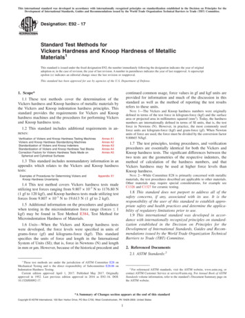
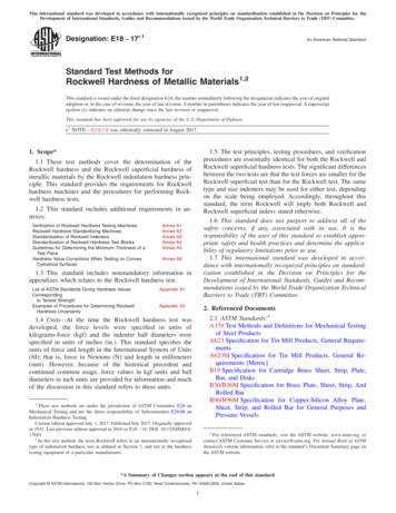
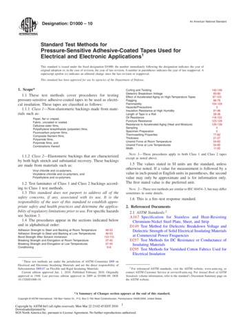
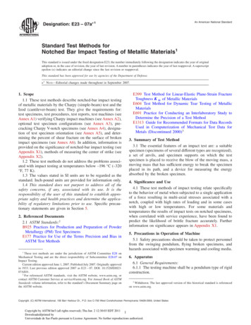
E23 – 07a 16.1.2 The testing machine shall be designed and built toconform with the requirements given in Annex A1.6.2 Inspection and Verification6.2.1 Inspection procedures to verify impact machines directly are provided in A2.2 and A2.3. The items listed in A2.2must be inspected annually.6.2.2 The procedures to verify Charpy V-notch machinesindirectly, using verification specimens, are given in A2.4.Charpy impact machines must be verified directly and indirectly annually.7. Test Specimens7.1 Configuration and Orientation:7.1.1 Specimens shall be taken from the material as specified by the applicable specification. Specimen orientationshould be designated according to the terminology given inAnnex A5.7.1.2 The type of specimen chosen depends largely upon thecharacteristics of the material to be tested. A given specimenNotch length to edgeAdjacent sides shall be atCross-section dimensionsLength of specimen (L)Centering of notch (L/2)Angel of notchRadius of notchLigament Length:Type A specimenType B and C specimenFinish requirementsmay not be equally satisfactory for soft nonferrous metals andhardened steels; therefore, many types of specimens arerecognized. In general, sharper and deeper notches are requiredto distinguish differences in very ductile materials or whenusing low testing velocities.7.1.3 The specimens shown in Figs. 1 and 2 are those mostwidely used and most generally satisfactory. They are particularly suitable for ferrous metals, excepting cast iron.47.1.4 The specimen commonly found suitable for die-castalloys is shown in Fig. 3.7.1.5 The specimens commonly found suitable for PowderMetallurgy (P/M) materials are shown in Figs. 4 and 5. P/Mimpact test specimens shall be produced following the procedure in Practice B925. The impact test results of these materialsare affected by specimen orientation. Therefore,4Report of Subcommittee XV on Impact Testing of Committee A-3 on Cast Iron,Proceedings, ASTM, Vol 33 Part 1, 1933.90 62 90 6 10 min6 0.075 mm 0, 2.5 mm6 1 mm61 60.025 mm60.025 mm60.025 mm60.075 mm2 µm on notched surface and opposite face; 4 µm on other two surfacesFIG. 1 Charpy (Simple-Beam) Impact Test Specimens, Types A, B, and CCopyright by ASTM Int'l (all rights reserved); Thu Jun 2 12:30:03 EDT 20112Downloaded/printed byUniversidade de Sao Paulo pursuant to License Agreement. No further reproductions authorized.
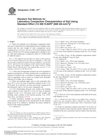
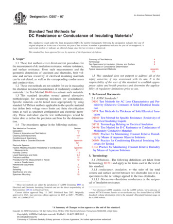
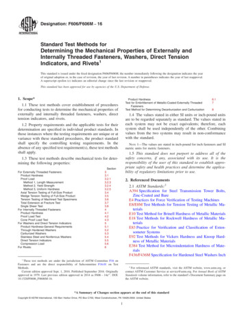
E23 – 07a 1NOTE 1—Permissible variations shall be as follows:Notch length to edgeCross-section dimensionsLength of specimenAngle of notchRadius of notchLigament LengthAdjacent sides shall be atFinish requirements90 62 60.025 mm 0, 2.5 mm61 60.025 mm60.025 mm90 6 10 min2 µm on notched surface and opposite face; 4 µm on other two surfacesFIG. 2 Izod (Cantilever-Beam) Impact Test Specimen, Type DNOTE 1—Two Izod specimens may be cut from this bar.NOTE 2—Blow shall be struck on narrowest face.FIG. 3 Izod Impact Test Bar for Die Castings AlloysCopyright by ASTM Int'l (all rights reserved); Thu Jun 2 12:30:03 EDT 20113Downloaded/printed byUniversidade de Sao Paulo pursuant to License Agreement. No further reproductions authorized.
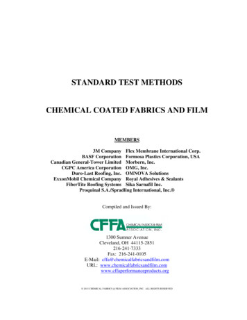
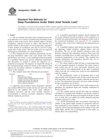
E23 – 07a 1DimensionsL- Overall LengthW-WidthT-Thicknessmmin.55.0 6 1.010.00 6 0.1310.00 6 0.132.16 6 0.040.394 6 0.0050.394 6 0.005NOTE 1—Adjacent sides shall be 90 6 10 min.FIG. 4 Unnotched Charpy (Simple Beam) Impact Test Specimen for P/M Structural MaterialsDimensionsL- Overall LengthW-WidthT-Thicknessmmin.75.0 6 1.5†10.00 6 0.1310.00 6 0.132.95 6 0.060.394 6 0.0050.394 6 0.005NOTE 1—Adjacent sides shall be 90 6 10 min.† Editorially corrected in August 2007.FIG. 5 Izod (Cantilever-Beam) Impact Test Specimen for P/M Structural Materialsunless otherwise specified, the position of the specimen inthe machine shall be such that the pendulum will strike asurface that is parallel to the compacting direction. For P/Mmaterials the impact test results are reported as unnotchedabsorbed impact energy.7.1.6 Sub-size and supplementary specimen recommendations are given in Annex A3.7.2 Specimen Machining:7.2.1 When heat-treated materials are being evaluated, thespecimen shall be finish machined, including notching, afterthe final heat treatment, unless it can be demonstrated that theimpact properties of specimens machined before heat treatmentare identical to those machined after heat treatment.7.2.2 Notches shall be smoothly machined but polishing hasproven generally unnecessary. However, since variations innotch dimensions will seriously affect the results of the tests,adhering to the tolerances given in Fig. 1 is necessary (Appendix X1.2 illustrates the effects from varying notch dimensionson Type A specimens). In keyhole specimens, the round holeshall be carefully drilled with a slow feed rate. The slot may becut by any feasible method, but care must be exercised incutting the slot to ensure that the surface of the drilled holeopposite the slot is not damaged.7.2.3 Identification marks shall only be placed in the following locations on specimens: either of the 10-mm squareends; the side of the specimen that faces up when the specimenCopyright by ASTM Int'l (all rights reserved); Thu Jun 2 12:30:03 EDT 20114Downloaded/printed byUniversidade de Sao Paulo pursuant to License Agreement. No further reproductions authorized.
E23 – 07a 1is positioned in the anvils (see Note 1); or the side of thespecimen opposite the notch. No markings, on any side of thespecimen, shall be within 15 mm of the center line of the notch.An electrostatic pencil may be used for identification purposes,but caution must be taken to avoid excessive heat.NOTE 1—Careful consideration should be given before placing identification marks on the side of the specimen to be placed up when positionedin the anvils. If the test operator is not careful, the specimen may be placedin the machine with the identification marking resting on the specimensupports. Under these circumstances, the absorbed energy value obtainedmay be unreliable.8. Procedure8.1 Preparation of the Apparatus:8.1.1 Perform a routine procedure for checking impactmachines at the beginning of each day, each shift, or just priorto testing on a machine used intermittently. It is recommendedthat the results of these routine checks be kept in a log book forthe machine. After the testing machine has been ascertained tocomply with Annex A1 and Annex A2, carry out the routinecheck as follows:8.1.1.1 Visually examine the striker and anvils for obviousdamage and wear.8.1.1.2 Check the zero position of the machine by using thefollowing procedure: raise the pendulum to the latched position, move the pointer to near the maximum capacity of therange being used, release the pendulum, and read the indicatedvalue. The pointer should indicate zero on machines readingdirectly in energy. On machines reading in degrees, the readingshould correspond to zero on the conversion chart furnished bythe machine manufacturer.NOTE 2—On machines that do not compensate for windage and frictionlosses, the pointer will not indicate zero. In this case, the indicated values,when converted to energy, shall be corrected for frictional losses that areassumed to be proportional to the arc of swing.8.1.1.3 To ensure that friction and windage losses are withinallowable tolerances, the following procedure is recommended: raise the pendulum to the latched position, move thepointer to the negative side of zero, release the pendulum andallow it to cycle five times (a forward and a backward swingtogether count as one swing), prior to the sixth forward swing,set the pointer to between 5 and 10 % of the scale capacity ofthe dial, after the sixth forward swing (eleven half swings),record the value indicated by the pointer, convert the reading toenergy (if necessary), divide it by 11 (half swings), then divideby the maximum scale value being used and multiply it by 100to get the percent friction. The result, friction and windage loss,shall not exceed 0.4 % of scale range capacity being tested andshould not change by more than 10 % of friction measurementspreviously made on the machine. If the friction and windageloss value does exceed 0.4 % or is significantly different fromprevious measurements, check the indicating mechanism, thelatch height, and the bearings for wear and damage. However,if the machine has not been used recently, let the pendulumswing for 50 to 100 cycles, and repeat the friction test beforeundertaking repairs to the machine.8.2 Test Temperature Considerations:8.2.1 The temperature of testing affects the impact properties of most materials. For materials with a body centered cubicstructure, a transition in fracture mode occurs over a temperature range that depends on the chemical composition andmicrostructure of the material. Test temperatures may bechosen to characterize material behavior at fixed values, orover a range of temperatures to characterize the transitionregion, lower shelf, or upper shelf behavior, or all of these. Thechoice of test temperature is the responsibility of the user ofthis test method and will depend on the specific application.For tests performed at room temperature, a temperature of 206 5 C (68 6 9 F) is recommended.8.2.2 The temperat
in 1933. Last previous edition approved 2007 as E23 – 07. DOI: 10.1520/E0023-07AE01. 2 For referenced ASTM standards, visit the ASTM website, www.astm.org, or File Size: 679KBPage Count: 28