Transcription
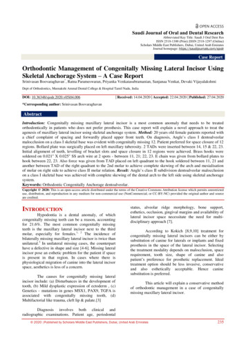
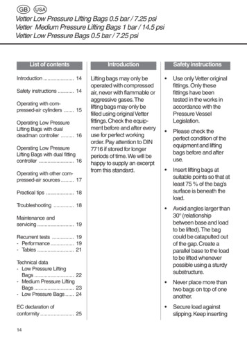
www.PDHcenter.comPDH Course C155www.PDHonline.orgExample (2.0)Using the Rankine method of analysis, calculate the factors of safety with respect tosliding, overturning and bearing capacity. Use the values presented in the followingTable and refer to Figure 5. It is inferred that all calculations relate to a unit length ofwall.Friction angle of soil backfill (φ)Soil Backfill Unit Weight (γ)32 degrees125 pcfFriction angle of the foundation soil (φ1)Rankine active pressure coefficient (Ka)33 degreesConcrete Unit Weight (γc)Dimensions of the concrete wall section 1150 pcf1-ft by 8-ftDimensions of the soil backfill section 24-ft by 8-ftDimensions of the concrete wall section 36-ft by 1-ft0.307Note:Since Pa is horizontal, there is novertical component of the force. Ifthe backfill surface were sloping thenPa would slope at an angle parallel tothe backfill slope. In this case therewould be both a vertical andhorizontal component of Pa. Thelateral thrust would be the horizontalcomponent and the verticalcomponent would be an additionalvertical force included in ΣV.Figure 5Page 18 of 20
www.PDHcenter.comPDH Course C155www.PDHonline.orgSolutionCalculate the values shown in the following Table. The dimensions for “Area” relate toeach of the three sections identified in Figure 3. The unit weight (γ) is provided for theconcrete wall and soil backfill over the base of the wall. W is the weight of each sectionand it acts at the centroid of the mass area as shown in Figure 3. The value “m” is themoment arm measured from the toe to the location of the individual W values. M is theresisting moment for each of the individual areas.W (lbs)m (ft)M (ft-lb)1x8γ 0SectionArea (sf)1ΣV 6100ΣMr 20500Pa ½ Ka γ H2 (0.5) (0.307) (125) (81) 1554.2 lbsΣMo Pa (h) (1554.2) (3) 4662.6 ft-lbsOverturning: Fso ΣMr / ΣMo 20500 / 4662.6 4.4 2 OKSliding:FSs ΣV tan(kφ1) / Pah (6100) tan (22) / 1554.2 1.58 1.5 OKWhere k 2/3Bearing Capacity:Assume that the ultimate bearing capacity of the foundation soil is 5000 psf.e (B / 2) - (ΣΜr ΣMo) / ΣV (6 / 2) – (20500 – 4662.6) / 6100 0.4 (i.e. e B / 6)qmax (ΣV / B) (1 6e / B) (6100 / 6) ( 1 2.4 / 6) (1016.6) (1.4) 1423.4 psfqmin (ΣV / B) (1 - 6e / B) (6100 / 6) ( 1 - 2.4 / 6) (1016.6) (.6) 610 psf (i.e. baseof wall is in full soil contact)FSbc qu / qmax 5000 / 1423.4 3.5 3.0 OKPage 19 of 20
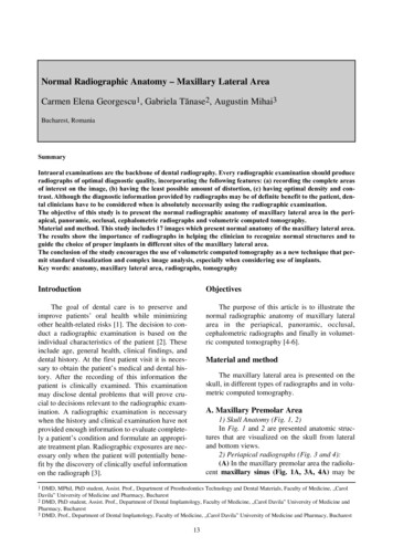
Project: Verification ExampleEngineer: Javier Encinas, PEDescrip: Wall Stability ExampleASDIP Retain 3.0.0CANTILEVER RETAINING WALL DESIGNGEOMETRYConc. Stem Height .Stem Thickness Top .Stem Thickness Bot .Footing Thickness .Toe Length .Heel Length .Soil Cover @ Toe .Backfill Height .Backfill Slope Angle .8.0012.012.012.01.004.000.008.000.0SEISMIC EARTH FORCESHor. Seismic Coeff. kh .0.00Ver. Seismic Coeff kv .0.00Seismic Active Coeff. Kae0.28Seismic Force Pae-Pa .-0.1ftininftftftftftOKdegk/ftSOIL BEARING PRESSURESAllow. Bearing Pressure .4.0 ksfMax. Pressure @ Toe .1.4 ksfMin. Pressure @ Heel .0.6 ksfTotal Footing Length .6.00 ftFooting Length / 6 .1.00 ftResultant Eccentricity e .0.40 ftResultant is Within the Middle ThirdOKPage #6/29/2014www.asdipsoft.comAPPLIED LOADSUniform Surcharge .0.0 psfStrip Pressure .0.0 psfStrip 2.0 ft deep, 4.0 ft wide @ 3.0 ft from StemStem Vertical (Dead) .0.0 k/ftStem Vertical (Live) .0.0 k/ftVertical Load Eccentricity6.0 inWind Load on Stem .0.0 psfBACKFILL PROPERTIESBackfill Density .125.0 pcfEarth Pressure Theory .Rankine ActiveInternal Friction Angle .32.0 degActive Pressure Coeff. Ka0.3138.4 psf/ftActive Pressure @ Wall .Active Force @ Wall Pa .1.6 k/ftWater Table Height .0.00 ftSHEAR KEY DESIGNShear Key Depth .0.0Shear Key Thickness .0.00.0Max. Shear Force @ Key .0.00Shear Capacity Ratio .No shear key has been specified0.00Moment Capacity Ratio .inink/ftOKOK1
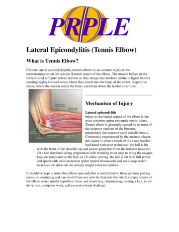
Project: Verification ExampleEngineer: Javier Encinas, PEDescrip: Wall Stability ExamplePage #6/29/2014CANTILEVER RETAINING WALL DESIGNwww.asdipsoft.comOVERTURNING CALCULATIONS (Comb. D H W)OVERTURNINGForce Arm Momentk/ftftk-ft/ftBackfill Pa .1.563.004.7Stem Top .Water Table .0.000.330.0Stem Taper .Surcharge Hor .0.004.500.0CMU Stem at Top .Strip Load Hor .0.004.000.0Footing Weight .Wind Load .0.006.500.0Shear Key .Seismic Pae-Pa .0.005.400.0Soil Cover @ Toe .Seismic Water .0.000.330.0Stem Wedge .Seismic Selfweight0.000.000.0Backfill Weight .Rh 1.56OTM 4.7Backfill Slope .Water Weight .4.7Seismic Pae-Pa .Arm of Horizontal Resultant 3.00 ft1.56Pa Vert @ Heel .20.5Arm of Vertical Resultant 3.36 ftVertical Load .6.10Surcharge Ver .Overturning Safety Factor 20.5 4.39 2Strip Load Ver .4.7OKRv RESISTINGForce Arm .00.001.500.00.004.000.00.004.000.0RM 20.56.10ASDIP Retain 3.0.0STEM DESIGN (Comb. 0.9D 1.6H 809.73.813.20.290.009.75.213.20.40 OKShear Force @ Crit. Height .1.8 k/ftOKResisting Shear ϕVc . 11.0 k/ftUse vertical bars #5 @ 12 in at backfill sideDo not cut off alternate vertical barsVert. Bars Embed. Ldh Reqd .8.3 inOKVert. Bars Splice Length Ld . 14.2 inSLIDING CALCS (Comb. D H W)Footing-Soil Friction Coeff. .0.40Friction Force at Base .2.4 k/ft3.25Passive Pressure Coeff. Kp .Depth to Neglect Passive .1.00 ftPassive Pressure @ Wall . Infinity psf/ftPassive Force @ Wall Pp .0.0 k/ft2.4 k/ftHoriz. Resisting Force .1.6 k/ftHoriz. Sliding Force .2.4Sliding Safety Factor 1.57 1.5 OK1.61234LOAD COMBINATIONS (ASCE 7)STABILITYSTRENGTHD H W1 1.4DD L H W2 1.2D 1.6(L H)D H 0.7E3 1.2D 0.8WD L H 0.7E4 1.2D L 1.6W5 1.2D L E6 0.9D 1.6H 1.6W27 0.9D 1.6H E
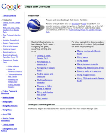
Project: Verification ExampleEngineer: Javier Encinas, PEDescrip: Wall Stability ExampleASDIP Retain 3.0.0CANTILEVER RETAINING WALL DESIGNHEEL DESIGN (Comb. 1.4D)Force Arm Momentk/ftftk-ft/ftUpward Pressure .0.01.330.0Concrete Weight .0.52.001.1Backfill Weight .3.62.007.2Backfill Slope .0.02.670.0Water Weight .0.02.000.0Surcharge Ver. .0.02.000.0Strip Load Ver. .0.02.000.04.1Mu 12.96.4 k/ftShear Force @ Crit. Sect. .11.0 k/ftResisting Shear ϕVc .Use top bars #5 @ 12 in , Transv. #4 @ 12 inResisting Moment ϕMn . 13.2 k-ft/ftDevelop. Length Ratio at End .0.300.63Develop. Length Ratio at Toe .OKOKOKOKPage #6/29/2014www.asdipsoft.comTOE DESIGN (Comb. 1.2D 1.6(L H))Force Arm Momentk/ftftk-ft/ftUpward Presssure1.90.511.0Concrete Weight .-0.20.50-0.1Soil Cover .0.00.500.01.70.9Mu 0.5 k/ftShear Force @ Crit. Sect. .9.9 k/ftResisting Shear ϕVc .Use bott. bars #5 @ 12 in , Transv. #4 @ 12 inResisting Moment ϕMn .11.8 k-ft/ftDevelop. Length Ratio at End .0.120.02Develop. Length Ratio at Stem .MATERIALSStem FootingConcrete f'c .4.04.0Rebars fy .60.060.0ksiksi3OKOKOKOK
Project: Verification ExampleEngineer: Javier Encinas, PEDescrip: Wall Stability ExampleASDIP Retain 3.0.0CANTILEVER RETAINING WALL DESIGNDESIGN CODESGeneral Analysis .Concrete Design .Masonry Design .Load Combinations .Page #6/29/2014www.asdipsoft.comIBC-12ACI 318-11MSJC-11ASCE 7-054
Project: Verification ExampleEngineer: Javier Encinas, PEDescrip: Wall Stability ExampleCANTILEVER RETAINING WALL DESIGNASDIP Retain 3.0.0Page #6/29/2014www.asdipsoft.comConc. Stem Height .ftUniform Surcharge .psfStem Thickness Top .inStrip Pressure .psfStem Thickness Bot .inFooting Thickness .ftStem Vertical (Dead) .k/ftToe Length .ftStem Vertical (Live) .k/ftHeel Length .ftVertical Load Eccentricity .inSoil Cover @ Toe .ftWind Load on Stem .psfBackfill Height .ftWind Height from Top .ftBackfill Slope Angle .degWall taperOKaTan ((12.0 - 12.0) / 12 / 8.00) 0.000 radBackfill slope0.0 * 3.14 / 180 0.000 radInternal frictionWall-soil friction32.0 * 3.14 / 180 0.559 rad0.559 / 2 0.279 radSeismic angleaTan (0 / (1 - 0)) 0.000 radFooting length1.00 12.0 / 12 4.00 6.00 ftHeight for Stability0.00 8.00 12.0 / 12 9.00 ftEarth pressure theory Rankine ActiveMoist density 125 pcfActive coefficientActive pressureSaturated density 130 pcf 0.310.31 * 125.0 38.4 psf/ft of height- For stability analysis (non-seismic)Active force0.31 * 125.0 * 9.00² / 2 1.6 k/ft1.6 * Cos (0.000) 1.6 k/ft ,1.6 * Sin (0.000) 0.0 k/ftWater forcePw (0.31 * (130.0 - 62.4 - 125.0) 62.4) * (0.00 12.0 / 12)² / 2 0.0 k/ft- For stem design (non-seismic)Active force0.31 * 125.0 * 8.00² / 2 1.2 k/ft1.2 * Cos (0.000) 1.2 k/ft ,1.2 * Sin (0.000) 0.0 k/ftWater forcePw (0.31 * (130.0 - 62.4 - 125.0) 62.4) * 0.00² / 2 0.0 k/ft1
Project: Verification ExampleEngineer: Javier Encinas, PEDescrip: Wall Stability ExamplePage #6/29/2014CANTILEVER RETAINING WALL DESIGNASDIP Retain 3.0.0Active seismic coeff.www.asdipsoft.com 0.28- For stability analysis (seismic)Seismic force0.28 * 125.0 * 9.00² / 2 * (1 - 0.0 ) 1.4 k/ft1.4 * Cos (0.279 0.000) 1.4 k/ft1.4 * Sin (0.279 0.000) 0.4 k/ftWater forcePwe 0.00 * (130.0 - 125.0) * (0.00 12.0 / 12)² / 2 0.0 k/ft- For stem design (seismic)Seismic force0.28 * 125.0 * 8.00² / 2 1.1 k/ft1.1 * Cos (0.279 0.000) 1.1 k/ft1.1 * Sin (0.279 0.000) 0.3 k/ftWater forcePwe 0.00 * (130.0 - 125.0) * 0.00² / 2 0.0 k/ftBackfill Arm 1.0 * 1.6 1.6 k/ft9.00 / 3 3.00 ftMoment 1.6 * 3.00 4.7 k-ft/ftWater table 1.0 * 0.0 0.0 k/ftArm (0.00 12.0 / 12) / 3 0.33 ftSurcharge Arm Moment 0.0 * 0.33 0.0 k-ft/ft1.0 * 0.31 * 0.0 * 9.00 0.0 k/ft9.00 / 2 4.50 ftMoment 0.0 * 4.50 0.0 k-ft/ftStrip load 0.0 k/ftArm 4.00 ftMoment 0.0 * 4.00 0.0 k-ft/ftWind load 1.0 * 0.0 * 5.00 0.0 k/ftArm 12.0 / 12 8.00 - 5.00 / 2 6.50 ftMoment 0.0 * 6.50 0.0 k-ft/ft0.0 * (1.4 - 1.4) 0.0 k/ftBackfill seismic Arm 0.6 * 9.00 5.40 ftWater seismic Arm Moment 0.0 * 5.40 0.0 k-ft/ft0.0 * 0.0 0.0 k/ft(0.00 12.0 / 12) / 3 0.33 ftWall seismic Moment 0.0 * 0.33 0.0 k-ft/ft0.0 * (0.0 0.0 0.9) * 0.00 0.0 k/ftMoment 0.0 * (0.0 * (12.0 / 12 8.00 / 2) 0.0 * (12.0 / 12 8.00 / 3) 0.9 * 12.0 / 12 / 2) * 0.00 0.0 k-ft/ftHor. resultant Rh 1.6 0.0 0.0 0.0 0.0 0.0 0.0 0.0 1.6 k/ftOverturning moment OTM 4.7 0.0 0.0 0.0 0.0 0.0 0.0 0.0 4.7 k-ft/ftArm of hor. resultant 4.7 / 1.6 3.00 ft2
Project: Verification ExampleEngineer: Javier Encinas, PEDescrip: Wall Stability ExampleCANTILEVER RETAINING WALL DESIGNASDIP Retain 3.0.0Stem weightPage #6/29/2014www.asdipsoft.com1.0 * 12.0 / 12 * 8.00 * 0.15 1.2 k/ftArm 1.00 12.0 / 12 / 2 1.50 ftStem taperMoment 1.2 * 1.50 1.8 k-ft/ft1.0 * (12.0 - 12.0) / 12 * 8.00 / 2 * 0.15 0.0 k/ftArm 1.00 12.0 / 12 - (12.0 - 12.0) / 12 * 2 / 3 2.00 ftMoment 0.0 * 2.00 0.0 k-ft/ftCMU stem at top 0.0 k/ft1.00 0.0 / 12 / 2 0.00 ftArm Moment 0.0 * 0.00 0.0 k-ft/ftFtg. weight1.0 * 6.00 * 12.0 / 12 * 0.15 0.9 k/ftArm 6.00 / 2 3.00 ftMoment 0.9 * 3.00 2.7 k-ft/ftKey weight1.0 * 0.00 / 12 * 0.0 / 12 * 0.15 0.0 k/ftArm 1.00 0.0 / 12 / 2 1.00 ftSoil cover Moment 0.0 * 1.00 0.0 k-ft/ft1.0 * 1.00 * 0.00 * 125.0 0.0 k/ftArm 1.00 / 2 0.50 ftMoment 0.0 * 0.50 0.0 k-ft/ftStem wedge 1.0 * (12.0 - 12.0) / 12 * 8.00 / 2 * 125.0 0.0 k/ftArm 1.00 12.0 / 12 - (12.0 - 12.0) / 12 / 3 2.00 ftMoment 0.0 * 2.00 0.0 k-ft/ftBackfill weight Arm 1.0 * 4.00 * 8.00 * 125.0 4.0 k/ft6.00 - 4.00 / 2 4.00 ftMoment 4.0 * 4.00 16.0 k-ft/ftBackfill slope 1.0 * (4.0 (12.0 - 12.0) / 12) * 0.00 / 2 * 125.0 0.0 k/ftArm 6.00 - (4.00 (12.0 - 12.0) / 12) / 3 4.67 ftMoment 0.0 * 4.67 0.0 k-ft/ftWater Arm 1.0 * 4.00 * 0.00 * (130.0 - 125.0) 0.0 k/ft6.00 - 4.00 / 2 4.00 ft0.0 * (0.4 - 0.4) 0.0 k/ftSeismic Pae-Pa Arm 6.00 ftBackfill Pav Arm Moment 0.0 * 4.00 0.0 k-ft/ftMoment 0.0 * 6.00 0.0 k-ft/ft1.0 * 0.4 0.0 k/ft6.00 ftMoment 0.0 * 6.00 0.0 k-ft/ftConcentrated Arm 1.0 * 0.0 0.0 * 0.0 0.0 k/ft1.00 (12.0 - 6.0) / 12 1.50 ftMoment 0.0 * 1.50 0.0 k-ft/ft3
Project: Verification ExampleEngineer: Javier Encinas, PEDescrip: Wall Stability ExampleASDIP Retain 3.0.0Page #6/29/2014CANTILEVER RETAINING WALL DESIGNSurcharge www.asdipsoft.com1.0 * (4.0 (12.0 - 12.0) / 12) * 0.0 0.0 k/ftArm 6.00 - (4.00 (12.0 - 12.0) / 12) / 2 4.00 ftMoment 0.0 * 4.00 0.0 k-ft/ftStrip 1.0 * 0.0 * 4.00 0.0 k/ftArm 6.00 - 4.00 / 2 4.00 ftVer. resultant Rv Moment 0.0 * 4.00 0.0 k-ft/ft6.1 k/ftResisting moment RM 20.5 k-ft/ftArm of ver. resultant 20.5 / 6.1 3.36 ftOverturning ratio 20.5 / 4.7 4.39Eccentricity - 6.002Bearing length - 2.00OK20.5 - 4.76.1 0.40 ftMin (6.00, 3 * (6.00 / 2 - 0.40)) 6.00 ftToe bearing 6.16.00 6 * 6.1 * 0.406.00² 1.4 ksfHeel bearing - 6.16.00-6 * 6.1 * 0.406.00² 0.6 ksf 4.0 ksfOK4
Project: Verification ExampleEngineer: Javier Encinas, PEDescrip: Wall Stability ExampleCANTILEVER RETAINING WALL DESIGNASDIP Retain 3.0.0Pass
www.PDHcenter.com PDH Course C155 www.PDHonline.org Page 18 of 20 Example (2.0) Using the Rankine method of analysis, calculate the factors of safety with respect to sliding, overturning and bearing capacity. Use the values presented in the following Table and refer to Figure 5. It is inferred that all calculations relate to a unit length of