Transcription
Windows Software for tensile testerSoftware User’s ManualFor Z3, Z5, Z10, Z20, Z50ZPM 4.7Last revision 29.01.20131/2 1
Windows Software for tensile testerContents1. Introduction . 32. Main window . 43. Test control panel . 54. Test settings panel . 65. Statistic panel. 86. Main menu .106.1 Menu “Data” .106.2 Menu “Test mode” .146.3. Menu Parameters .176.4. Menu “Options” .196.5 Menu “About” . 202/2 1
Windows Software for tensile tester1.IntroductionThis User’s Manual will familiarize you with the Software to operating the tensile testers Z3, Z5, Z10,Z20, Z50, and ZPM 4.7.Before using this software you need to install FTDI drivers for Tensile Tester (in text below –machine). You can find driver in programs folder or download it from FTDIchip websitehttp://www.ftdichip.com/Drivers/D2XX.htmIf you are not able to run this software from CD or flash drives, please copy program to HDD beforeyou use it.First run:1. Install FTDI driver (i.e. run: CDM20824 Setup.exe)2. Connect machine to USB port of your PC3. Choose number of Virtual COM port associated with your machine. You can use windows “devicemanager” or our special utility for detection www.gripsoft.de/current/machine detector.exe4. Enter the number of detected virtual com port in main menu "data"- ”comport” form(only digits, for example “2”).3/2 1
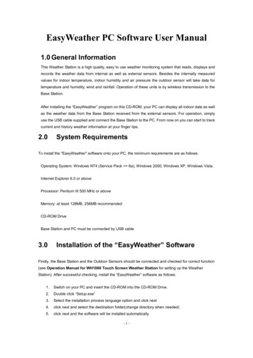
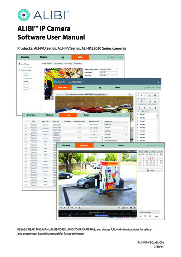
Windows Software for tensile tester2. Main windowTest control PanelMain lculationPanel usedby sometestsStatus PanelTest curveFigure 1. Main windowOn the Main Window (Figure 1) of this Software program you can see several buttons to accessvarious areas of the software, as follows:Test Control Panel is using for operating during the Test (See Chapter 3).On the Test settings Panel and the Statistic Panel you can put parameters and see settings of theTest (See Chapter 4 and 5).Main Menu is used to work with the Test Data (See Chapter 6).On the Status Panel you can see information about actual test curve point.Chart window includes 2 chart axes, test curve and charts.Chart window features:1.2.3.4.5.Double click on chart set auto scale chartUse right click of mouse and direction to zoom in and zoom out chart.Click on test curve calls Point info form (Figure 2).Move mouse over the curves to get info about current point in status panel.Move mouse over form elements to get additional hints in the status panel.4/2 1
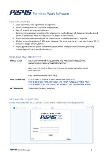
Windows Software for tensile testerFigure 2. Point info form2.Test control panelFigure 3. Test control panelTest control panel offers you buttons to start or to stop the Test.Pictogram NameShort DescriptionHot keysStopStops current testALT SStartStart new testALT TReturnAfter Test this button returns machine tostart pointALT RResetResets load cell and position encoder (setsvalues to 0 Force 0 actual Position is 0(Tara)ALT ECleanClears current chartOld curve will be deletedALT CInfoCalls Infodata form (Figure 4)ALT I5/2 1
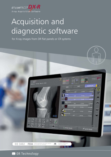
Windows Software for tensile testerFigure 4. Infodata formInfodata form is used for sample description after the Test.1. In “Pr. Number” field you can type test name (for example “test N1”).2. In “length“ field put the length of sample in [mm]. For correct calculations you should entercorrect value here (it used for elongation [%] calculation and etc).3. In “Sample description” field you can enter sample description. For example “Plastic tie 4x30mm”.4. In “Operator” field put the name or code of machine operator who makes current test.5. In “Method” field you should put test method. After test this field will be filled by software.Example: “standard”, “compression”, etc.6. In “Remark” field you can enter additional notes of test.7. In “Material” field you can enter material of sample.8. In “Delivery firm” field you can type customer firm name. This is an option.9. In “Serial name” field put serial number of sample.In page control fields (Figure 5) you should set width (W) and thickness (T) or diameter (D) of asample. These values are necessary to calculate the Tension (Sigma [N/mm2]). Cross area will becalculated automatically after entering values in W and T or D fields.Figure 5. Page control fields3.Test settings panel6/2 1
Windows Software for tensile testerTest settings panel is used to put Test Parameters. Also it shows Actual load (N) and Actual position[mm].Figure 6. Test settings panelDescription of buttons on the Test settings panelPictogramParameterNameShort DescriptionActual load [N]Shows current load on load cell [N]Actual position[mm]Shows actual value of position [mm]ModeActive mode name(Others are friction hysteresis compression peel)Speed[mm/min]Set speed of test [mm/min]Endpos [mm]Set target (end) position here. Machine stops atthis position if delta (break) force in not active7/2 1
Windows Software for tensile testerParameterNameShort DescriptionF0 preforce [N]Set preforce value. Program will not draw chartuntil this value is reached.F limit S [N]Set Limit Force. Machine will stop if this value offorce is reached. Safety parameter.F delta [N]Break force, when machine detects thisdifference between two values – rupture issupposed - machine stops testSend buttonSends current settings to machine. You have topush this button after any change of the settings.Pictogram3.Statistic panel8/2 1
Windows Software for tensile testerFigure 7. Statistic panelOn the Statistic panel you can find automatically filled statistic information and put value of the sample.Description of buttons on the statistic panelNameSampledescriptionDescriptionIn “Sample description” field set sample description. For example “Plastic tie4x30 mm”.FmaxMaximum Force reached due the test (program fills this field automatically,after end of test)XmaxPosition of Maximum Force reached due the test (program fills this fieldautomatically, after end of test)FbreakForce reached due sample break (program fills this field automatically, afterend of test)XbreakBreak point of sample (program fills this field automatically, after end of test)lengthSet here length of sampleWidthSet here width of sampleDiameterSet here diameter of sampleThicknessSet here thickness of sample9/2 1
Windows Software for tensile tester5. Main menuFigure 8. Main menuMain menu offers a different set to operating with the Test Data.5.1 Menu “data”Figure 9. Menu DataSave opens save dialog.Buffer will be saved as *.Bin file.Load opens load file dialog. You can open only *. Bin files. If you want to open many files, justselect them and press open.End Closes programPrint opens print dialog with different possibilities (Figure 10), as followsFigure 10. Menu Print Print whole chart Sends chart to printer. (Figure 11) Print advanced chart Prints chart with advanced properties. (Figure 12)10/2 1
Windows Software for tensile tester Print report Prints Test report. (Figure 13)Figure 11. Printed chart viewFigure 12. Advanced chart print form11/2 1
Windows Software for tensile testerFigure 13. Printed Test report12/2 1
Windows Software for tensile testerComport Com port setting form (Figure 14). Just put the com port number. Com port name youcan find in Windows Device Manager after installation FTDI driver and connecting machine to PCUSB port. Just put the number between 1 15.Figure 14. Com port set up formExport Exports data to Microsoft Excel. Here you can set decimal separator and other usefuloptions. Also you can select test if many tests are present (Figure 15).Figure 15. Export options menu13/2 1
Windows Software for tensile tester5.2 Menu “Test mode”On the Menu Test mode you must choose desired type of test.Figure 16. Test modeSome tests have additional menu and calculation panels, as followsPeel testFigure 17. Peel test parameters formFriction testFigure 28. Friction test parameter formTensile Stress/Strain14/2 1
Windows Software for tensile testerFigure 39. Tensile Stress calculations formYou can find the Tensile Stress calculations form on the Addition calculation Panel (see Figure 1).Use pop up menu on this panel to access to additional calculation parameters (Figure 20) and youcan use it to print report (Figure 14).Figure 20. Tensile test calculation parametersBending test15/2 1
Windows Software for tensile testerFigure 21. Bending Test calculations panelYou can find the Bending Test calculations on the Addition calculation Panel (see Figure 1). Usepop up menu on this panel to access to additional parameters and print report (figure 16).Figure 22.4 Bending test calculations form16/2 1
Windows Software for tensile tester5.3. Menu ParametersFigure 23. Menu ParametersProgram parameters calls programs parameters menu (Figure 24).Figure 24. Programs Parameters formCompany data form offers you a form for the general information about the Company (Figure 25).17/2 1
Windows Software for tensile testerFigure 25. Company data formThis information will be used to print report header (Figure 26).Figure 26. Test report header18/2 1
Windows Software for tensile tester5.4. Menu “Options”Figure 27. Menu OptionsIn the menu Options you find additional menus for Scaling (Figure 28), Change unit system (Figure29) and Languages (Figure 30).Figure 28.5 Scaling formFigure 29.6 Change unit system formFigure 30.7 Languages form19/2 1
Windows Software for tensile tester5.5 Menu “About”This form supplies info about software name version, developer and software version.Figure 31. About Form20/2 1
Windows Software for tensile testerFor sophisticated users:Adding the new language to Windows program seehttp://www.youtube.com/watch?v LDNiQRc5TIQ&feature youtu.behttp://www.youtube.com/watch?v WoxhJpFdETE21/2 1
Enter the number of detected virtual com port in main menu "data"- ”comport” form (only digits, for example “2”). Windows Software for tensile tester 4/21 2. Main window Figure 1. Main window On the Main Window (Figure 1) of this Software program you can see several buttons to access various areas of the software, as follows: Test Control Panel is using for operating during the Test .