Transcription
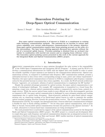
Beaconless Pointing forDeep-Space Optical CommunicationAaron J. Swank Eliot Aretskin-Hariton†Adam WroblewskiDzu K. Le†Obed S. Sands‡§NASA Glenn Research Center, Cleveland, OH, 44135Free space optical communication is of interest to NASA as a complement to existingradio frequency communication methods. The potential for an increase in science datareturn capability over current radio-frequency communications is the primary objective.Deep space optical communication requires laser beam pointing accuracy on the order of afew microradians. The laser beam pointing approach discussed here operates without theaid of a terrestrial uplink beacon. Precision pointing is obtained from an on-board startracker in combination with inertial rate sensors and an outgoing beam reference vector.The beaconless optical pointing system presented in this work is the current approach forthe Integrated Radio and Optical Communication (iROC) project.I.Introductionroviding communication services to space missions throughout the solar system is the responsibilityPof the NASA Space Communication and Navigation (SCaN) Program. A primary goal for SCaN is todevelop a communications infrastructure for NASA with the highest data rates feasible in order to ensure1the scientific capability of space missions is not limited by the communications infrastructure. Optical communications systems, as compared to traditional radio frequency (RF) communication methods, promise asubstantial increase in data return with a corresponding savings in mass, power and volume requirements.2Therefore, free-space optical communication is of interest to NASA to complement radio frequency communication for the potential increase in science data return capability. As a result, the SCaN network architecturefeatures “aggressive, yet systematic, infusion of optical communications to complement the RF baseline”.1Despite the potential advantages presented by optical systems, free-space optical communication is notabsent of technological challenges. For example, RF communication is transmitted in a broad beam illuminating a target area, whereas optical communication utilizes a comparatively narrow beam, pointed at asingle receiver. While the narrow optical beam results in more efficient use of the electromagnetic spectrumas compared to RF, free-space optical communication is challenged by more stringent pointing and trackingrequirements due to optical beam divergence. State-of-practice methods for space-based optical communication rely on closed-loop tracking of an Earth-based optical beacon in order to maintain the satelliteoptical terminal pointing direction towards the ground-station receiver. The Lunar Laser CommunicationDemonstration (LLCD), for example, has demonstrated that a beacon-aided laser communications techniqueis feasible for near to Earth orbiting satellites.3, 4 Yet for deep space optical communication, such as fromMars or beyond, beacon-aided optical communication becomes less practical as the distance increases.2 Asa result, alternatives to beacon-based laser communications are being investigated.2, 5–7The work presented here is motivated in support of the optical communications system for the IntegratedRadio and Optical Communication (iROC) project. The iROC project is a research and development effortto couple deep space radio frequency and optical communication elements into an integrated system for communication to Earth at distances from Mars and beyond. iROC enables insertion of optical communication ResearchEngineer, Information and Signal Processing BranchTechnologist Control Engineer, Intelligent Control and Autonomy Branch‡ Research Electronics Engineer, Information and Signal Processing Branch§ Research Engineer, Optics and Photonics Branch† Aerospace1 of 11American Institute of Aeronautics and Astronautics
Figure 1. Beaconless pointing for deep-space optical communication.technology into the NASA communication infrastructure with reduced infusion risk, while leveraging the distinct advantages that both RF and optical techniques provide. The iROC system utilizes a combined RF andoptical teletenna (telescope/antenna) to produce a co-boresighted microwave and optical communicationssystem. Additional information on the iROC project and overall design is available in Raible et. al.2A.Beaconless PointingFor precision pointing of the optical communications laser, the iROC project is investigating the useof a beaconless pointing approach, whereby no uplink beacon is used (Figure 1). While a beacon-aidedtechnique is likely sufficient for a number of applications, an uplink beacon technique is problematic fordeep space applications. High intensity laser power is required to reach the extents of deep space and thesatellite telescope design requires a large aperture to receive a dim uplink beacon with sufficient intensityfor detection. The technique is further complicated by terrestrial cloud obscuration.8 Furthermore, thehigh intensity uplink beacon poses usage constraints with respect to airspace penetration to avoid air trafficdisruption (e.g. for eye safety issues), as well as risk mitigation to orbiting satellites with Earth observingpayloads.8, 9 Although the advantages of a beaconless pointing approach to optical communication havebeen identified, a beaconless optical communication system has yet to be demonstrated. As a result, theInteragency Operations Advisory Group (IOAG), Optical Link Study Group (OLSG), which was setup tomake an intensive study on the operation of optical communications, concluded as a level two priority that “inparallel to the beacon standardization, the space agencies should conduct a rigorous detailed study . . . todetermine if there are ways of accomplishing beaconless pointing, acquisition and tracking (PAT)”.9 Inaddition to motivations outlined by the OLSG, the potential advantages of the beaconless pointing approachinclude: beacon receive requirements imposed on spacecraft are eliminated permits optimization of aperture, laser power and pointing knowledge2(e.g. no minimum telescope aperture size required to detect a dim beacon) operation is independent of beacon cloud obscuration resulting in increased spacecraft autonomy high power uplink beacon not required eliminates eye safety concerns from uplink beacon; laser clearing house coordination not necessaryIt is therefore desirable to consider alternate designs, which do not utilize the uplink beacon to aid theoptical pointing system. The following sections outline the current baseline approach to the iROC beaconlesspointing system.2 of 11American Institute of Aeronautics and Astronautics
II.MethodologyOperating a deep-space optical communications system in a beaconless fashion is challenging becausethe system is operating open loop without feedback of the pointing error directly from the receiving groundstation. An uplink beacon, for example, would close the feedback loop and provides the necessary relativeoffset information to correct the pointing direction vector. In absence of an uplink beacon, pointing errorfeedback information must be generated using sensors on-board the spacecraft. As a result, the beaconlessapproach requires a precise and absolute pointing direction estimate for the outgoing beam. Furthermore,the desired pointing direction for the outgoing beam must be maintained by the pointing control system. Ingeneral, the pointing subsystem components required to establish a beaconless optical communication linkmay be summarized to include: A) optical platform attitude estimation, B) outgoing beam direction vectorestimation, C) optical line of sight stabilization, and D) system control.A.Optical Platform Attitude EstimationOptical platform attitude estimation requires either relative attitude information from a known pointingdirection, or absolute pointing knowledge coupled with target location information. Sources for optical beampointing direction information, which do not utilize an artificial uplink beacon, may be grouped into twogeneral categories: 1. using Earth signatures as a virtual beacon (at various wavelengths) for relative pointinginformation, and 2. using celestial sources (e.g. stars) and inertial sensors for absolute attitude information.Concepts using signatures of the Earth as a virtual beacon source has been discussed in the literature forboth the visible and long-wave infra-red regimes.10–13 Regardless of the observed wavelength, using theEarth for line of sight vector information has an issue with non-uniformity of the signal and limited signalstrength. As a result, signal centroiding will not necessarily coincide with the geometric center of the Earth,limiting the accuracy of the approach. As an alternative, celestial sources can provide attitude and pointinginformation by using star tracker devices. Star trackers provide very accurate absolute pointing information,with precision on the order of a microradian and advanced technologies reaching the sub microradian range.Further advancements in star tracker technology is expected with improved technologies, including sensortechnology and maturation of interferometric star tracker methods14, 15 as well as significantly improved starcatalog information (over 100 increase in accuracy) using precision astrometry results from the EuropeanSpace Agency (ESA) Gaia mission to reach accuracies better than 100 picoradians.16–18For establishing beaconless optical communication from Mars to Earth, the iROC design2 requires anoptical beam pointing accuracy on the order of 2-5 µrad. Precision attitude information, combined withsatellite state information, is sufficient for optical beam pointing information. Using celestial sources togenerate the optical platform attitude estimate is the baseline approach of the iROC project. Here, a startracker and an Inertial Reference Unit (IRU) are co-located on the optical bench. The star tracker informationis combined with the high-rate IRU information for direct attitude determination of the optical platform. Incontrast to other systems requiring precision attitude information for scientific payloads, attitude informationoriginates from the optical bench platform rather than from sensors located on the spacecraft. As a result,the configuration does not require methods to measure and correct for the relative motion between thespacecraft attitude sensors and optical bench, such as an elaborate metrology system or reverse kinematicestimation algorithms for the pointing gimbal mechanism. In this application the IRU gyroscope informationprovides relative change in attitude information through either a delta angle or angular rate value. Thegyroscope angular rate (or delta angle) information is used to propagate the optical platform attitude at arate sufficiently high to capture the optical platform dynamics. Currently it is estimated that an output rateof several hundred Hz is sufficient for the iROC application. A multiplicative Extended Kalman Filter (EKF)corrects for the gyro drift and estimates an absolute pointing direction of the optical platform using the startracker information and the propagated attitude estimate from the gyroscopesa. The EKF is updated at therate of the star tracker measurement rate. Details of the EKF formulation is out of the scope of this paper,yet detailed information on the multiplicative EKF approach for attitude estimation is widely published.19–23a The multiplicative EKF state vector implemented in this work consists of a three-part modified Gibbs vector as an estimateof attitude and a three-part gyro bias estimate.3 of 11American Institute of Aeronautics and Astronautics
(a) Notional iROC optical assembly(b) Outgoing beam shown with star field.Figure 2. Fig. 2(a): Star tracker sensor mounted in a notional iROC assembly for direct measurement of theoutgoing beam direction. A fraction of the outgoing communications beam is redirected into the interferometricstar tracker. Fig. 2(b): Effective view field of interferometric star tracker. The angular differences (blue)between outgoing communications beam (red circle) and reference stars are on a common sensor.B.Outgoing Beam Direction Vector EstimationDetermining the direction of the outgoing communication laser beam is a fundamental challenge of thebeaconless pointing approach. Since the desired line of sight vector is determined by knowledge of the receivestation location, the beam direction vector must be related to an inertial pointing direction. Determiningthe optical beam direction vector in inertial space typically requires a two-part approach, where one firstmeasures the attitude of the optical platform in inertial space (such as through utilization of a star trackerdevice), followed by estimating the beam’s direction vector relative to the optical platform. Although theoptical transmitter is designed with a high stiffness and low coefficient of thermal expansion material, theoptical assembly is subject to spatial deformation due to structural and thermal loads induced by a varietyof sources. For an accurate estimate of the beam direction vector, the design requires a method to measurethe relative motion between the attitude reference sensor and the communication beam. Disturbances suchas vibrational motion and thermal stability of structure and optical mounting components will contributeto beam motion, which is not common to the attitude information provided by the attitude sensor. For thedesign presented here, the problem is simplified (though not eliminated) by locating the star tracker on theoptical bench.A proposed approach for estimating the beam direction vector involves a direct measurement of theoutgoing beam direction with the star tracker sensor. Here, the star tracker detector is designed to besensitive in the short wave infra-red (SWIR) band to allow direct sensing of the 1550 nm communicationlaser and the star light on a common detector. As shown in Figure 2, the concept samples a small portion ofthe outgoing communication laser beam through the use of a hollow retro-reflector. Through exploitation of ahollow retro-reflector to sample the laser light after reflection from the primary mirror, the angular directionof the outgoing beam can be estimated since it is located along a vector parallel to the communication beam.This sampled beam is directed into the optics of the star tracker system for angular measurement of the beamdirection. By directly measuring the outgoing optical beam direction after any imposed disturbances, themeasurement directly relates the star tracker attitude information to the laser beam line of sight directionvector through a common sensor. Angular measurement of the incoming beam is possible through the use ofan interferometric star tracker device.14, 15 The interferometric measurement nature of the star tracker deviceis a key characteristic of the star tracker hardware necessary to implement this design. An interferometricstar tracker measures the incoming angle of the star/laser source rather than inferring an incoming anglethrough a centroiding technique typical of other star trackers. With an interferometric star tracker, a changein the light incident angle results in changes to a phase pattern, which allows for precise detection of angularmotion. Thus, by using an interferometric star tracker, the relative angular position between the laserbeam source and the star light source is precisely determined by a phase estimate calculation resulting inimproved accuracy as compared to a centroiding technique. In the current proposed design currently underdevelopment by the Optical Physics Company, the interferometric star tracker performance is expected to4 of 11American Institute of Aeronautics and Astronautics
/BEAMEXPANDERSTABLE SIDE OFVIBRATION ISOLATION PLATFORMActuatorRPSRPSActuatorSTABLE SIDE OFVIBRATION ISOLATIONPLATFORMSTARTRACKERSPACECRAFT SIDE OFVIBRATION ISOLATION PLATFORMCoarse Pointing(Gimbal)SPACECRAFTRETROREFLECTORSPACECRAFT SIDE OFVIBRATION ISOLATIONPLATFORM(a) Block Diagram(b) Solid ModelFigure 3. Stabilized platform beaconless pointing system. Fig. 3(a): The vibration isolation platform providesdisturbance suppression and fine steering capability for the optical beam. Fig. 3(b): Solid model rendering ofconceptual stabilized platform system. The coarse pointing (i.e. gimbal) assembly is not depicted in the solidmodel. Also not visible are the vibration isolation platform sensors and actuators, which are located betweenthe stable and spacecraft side of the vibration isolation platform.achieve better than 0.3 µrad attitude determination at 15 Hz.C.Optical Line of Sight StabilizationThe ability to stabilize and point the outgoing communications beam is an essential feature of a spaceoptical communication terminal. Disturbances to the pointing direction will be a result of a number of contributions. For example, in addition to spacecraft induced structural vibrational motion, thermal stability ofstructure and optical mounting components will also contribute to beam motion. Mechanical disturbancesfrom the host spacecraft and thermal beam wander must be accommodated with beam stabilization mechanisms integrated into the iROC terminal. Requirements for beam pointing accuracy and beam stabilizationfollow from requirements on power flux density of the transmit beam at the receive terminal and set theoverall pointing accuracy of the outgoing communications beam somewhere between 2-5 µrad noise equivalent angle (NEA). For the iROC system, generic requirements on the input mechanical disturbance profileat the spacecraft interface are assumed as per past and current deep-space optical communications development efforts. It is assumed here that the spacecraft design will not be optimized to reduce the disturbanceimparted on the optical communications system. For design purposes, a nominal (and conservative) spacecraft disturbance environment is assumed. Angular power spectral density with total integrated disturbancelevels in the range of 100-150 µrad root mean squared (RMS) are adopted for iROC.24, 25 Both three-axisrotational mechanical disturbances and three-axis translational mechanical disturbance are included in therequirements set. The iROC design should, therefore, be applicable to a wide range of spacecraft hosts.In order to achieve the desired pointing performance of 2-5 µrad for the iROC system, measures must betaken to stabilize the optical line of sight. For the iROC system, a beaconless stabilized platform approachis assumed for the communications terminal. As noted by Chen et. al26 the stabilized platform approacheliminates the need for high bandwidth beam stabilization control loop, including fast steering mirrorsand detectors. Recent innovations in component technologies such as star trackers and vibration isolationenable the approach. The key components of the stabilized platform approach are schematically depictedin Figure 3. The design consists of the iROC terminal, including the optical assembly and beam expander,located on a vibration isolation platform. The spacecraft side of the vibration isolation platform is connectedto the spacecraft interface through a coarse-pointing mechanism such as a gimbal assembly. Located on thestable side of the vibration isolation platform, is an absolute attitude sensor (e.g. the star tracker) and aninertial sensor (e.g. an IRU or gyroscope) for high-rate angle or angular rate information. The vibrationisolation platform not only reduces satellite vibrational disturbance contributions to the outgoing opticalbeam, but also stabilizes the star tracker co-located on the optical bench. As a result, reduced jitter isimparted on the star tracker focal plane array for improved attitude sensing. The stable side of the vibration5 of 11American Institute of Aeronautics and Astronautics
ICS/BEAMEXPANDERStable Side ofVibration IsolationPlatformActuatorLine of SightDeviationSTARTRACKERActuatorSTARTRACKERCoarse Pointing(Gimbal)Receive TerminalLine of Sight(b)(c)Figure 4. Stabilized platform control architecture. Fig. 4(a): Star tracker and outgoing communications beamalignment loop. The star tracker also provides updates to the outgoing beam direction vector estimates, orline of sight deviations. Fig. 4(b): Platform jitter rejection and fine-pointing control loop. The estimationfilter, e.g. EKF, provides an attitude for the stable side of the vibration isolation platform, which is used forplatform actuation. Fig. 4(c): Coarse pointing control loop. Coarse pointing of the platform is achieved by agimbal and driven by relative angular position sensor information.isolation platform is connected to the spacecraft side of the vibration isolation platform using a hinge jointor other motion-constraining device such as a flexure. Electro-mechanical actuators and relative angularposition sensor (RPS) are located between the stable and spacecraft side of the vibration isolation platformfor feedback control. The vibration isolation platform also supplies the fine pointing capability to the system,with microradian pointing control and stroke on the order of a milliradian. In the current design, emphasisis placed on disturbance suppression for the iROC terminal with minimal active beam control by steeringdevices. In the event that platform stabilization is not sufficient through laboratory testing, the design can beaugmented with a high-bandwidth laser metrology system coupled with fast steering mirrors for mechanicaljitter suppression. The resulting system would then be a hybrid, consisting of both beam stabilization andplatform stabilization.D.System ControlA simplified representation of the control loops for the stabilized beaconless platform is depicted inFigure 4. As described in Section B, registration of the outgoing communications beam to the star trackerattitude information is accomplished by feeding a portion of the outgoing communications beam into thestar tracker. Deviations in the location of the outgoing communications beam serve as an error signalto actuator(s) within the optical assembly to provide precise, low-rate control (at the star tracker updaterate and below) of the outgoing beam line of sight. The beam-alignment loop, as shown in Figure 4(a),compensates for effects such as thermal beam wander and other slowly varying effects which contribute tobeam line of sight deviation. Pointing system calibration is performed periodically by dithering the beamwith small pointing offsets around the receiver location and measuring changes in received power with offsetsin commanded beam pointing offsets. The received power levels are fit to commanded pointing offsets inorder to determine the center of the beam pattern. The nominal communications beam position in the startracker is then updated to accommodate for structural changes.Platform pointing and jitter rejection is accomplished through the control loop as shown in Figure 4(b).Platform attitude information from the star tracker is combined with inertial sensor (IRU or gyro) informationusing the EKF approach as described in Section A to yield high bandwidth stable-side attitude at the gyroupdate rate. The resulting attitude estimate is compared (subtracted) with the receive terminal line of sightvector and used to drive the isolation platform actuators for pointing and jitter rejection. Calculation of thereceive terminal line of sight vector must accommodate receive terminal motion occurring during the time offlight. As shown in Figure 4(c), control of the coarse pointing gimbal is derived from the RPS information,which measures the relative angle between the spacecraft and stable side of the vibration isolation platform.The coarse pointing gimbal offloads and decouples stable side pointing of the vibration isolation platform.By maintaining separate, decoupled control loops for a) beam alignment, b) jitter-rejection and fine pointing,and c) coarse pointing, the stabilized platform approach simplifies the design and analysis.6 of 11American Institute of Aeronautics and Astronautics
Table 1. IRU noise terms used for simulations.Gyro Class:Navigation StrategicNomenclatureUnitsAngle Random WalkBias Instability[deg/h1/2 ][deg/h]8e-41e-20.5e-41e-3Table 2. Star tracker noise equivalent angle values assumed for simulations.NomenclatureUnitsCross-Boresight NEABoresight NEASample Rate[µrad][µrad][Hz]III.ST500027Advanced ST2.682.4100.42.015SimulationTo assess the capabilities of the attitude solution created by a combined star tracker and IRU, an ExtendedKalman Filter software simulation was implemented. The performance of the EKF tool is first verified usingsimulation parameters representative of a test scenario for which results are available. After verification ofthe tool, the EKF performance is simulated for different star tracker and IRU configurations. The assumedvalues for the IRU and star tracker used for the simulations is compiled into Table 1 and Table 2.Forsimulated star tracker measurements, Gaussian white noise is added to a truth trajectory consisting of asinusoidal varying rotation at 100 µrad/s. To simulate an IRU measurement for the attitude determinationsimulations, a time series angular rate truth value is generated with simulated noise consisting of gyro angularrandom walk (ARW) and bias instability. Since the anticipated dynamics are small, the gyro scale factorstability is not considered as the errors are dominated by gyro drift. The angle error growth is dominatedover short time periods by ARW and over long time periods by the bias instability. Realistic gyro noisevalues are generated by shaping the spectral content of a Gaussian white noise sequence in the frequencydomain using power spectral density constructed from the asymptotic components as described in the IEEEStandard 952.28Verification of the EKF simulation is performed using hardware specifications similar to the WallopsArc Second Pointer (WASP) system, as flight performance data is published online.29 Initial WASP testflights used an LN-251 IRU produced by Northrop Grumman and the ST5000 star tracker produced by theUniversity of Washington.27 Key performance metrics of the LN-251 for the bias instability and ARW arenot published. As a result, values representative of a navigation grade gyro are assumed in the simulation.The performance characteristics for the NEA of the ST5000 is published27 and used in the simulations.Performance results of the navigation class gyro and ST5000 combination have been produced by severalWASP test flights, the most applicable to the baseline EKF scenario presented here is test flight two. Testflight two was performed with the star tracker and IRU in the control loop. While the EKF designed for thesimulation detailed in this paper contains only an attitude solution, it is assumed that adding a control loopcan only degrade, not improve, the final attitude solution. Results from the second WASP test flight showan attitude error on the order of 0.5 and 0.75 arcseconds (3-sigma) in the pitch and yaw respectively. Thiscorresponds to an attitude error of 0.8 µrad RMS in the pitch and 1.2 µrad RMS in the yaw. The resultsclosely match the predicted value from the EKF simulation shown in Figure 5 which shows an attitude errorof 1.15 µrad RMS in yaw and pitch. These results validate the EKF simulation as the results are on thesame order as the expected flight capabilities of a given star tracker and IRU combination.IV.Discussion and ResultsAs an example of the attitude determination performance expected to be available for iROC, a simulationof the EKF is performed with star tracker and inertial reference unit parameters representative of high7 of 11American Institute of Aeronautics and Astronautics
σΘ , [µ rad]σΦ , [µ sed Time, [sec]2530σΨ , [µ ) Attitude error from truth.5(b) EKF modified Gibbs vector covariance estimate.Figure 5. Attitude error from truth and Kalman filter Gibbs vector covariance estimate. The RMS error fromtruth is 1.15 µrad in the cross boresight directions (Θ, Φ) and 8.35 µrad around the boresight direction (Ψ).The extended Kalman filter converges in the cross boresight directions (Θ, Φ) within approximately 0.5 secand within 20.0 sec for the boresight direction (Ψ).performance devices. With the advent of interferometric star tracker technologies, one expects advancedstar tracker performance to reach the sub-microradian accuracies. For the inertial reference unit, a devicewith performance at the strategic grade gyro level is used. A strategic grade gyro and a next generationadvanced star tracker will provide an upper bound to the expected attitude estimation performance. Thehardware noise and performance values are provided in Table 1 and Table 2. The ARW value listed in thetable for the strategic grade gyro follows published values for the Scalable Inertial Reference Unit (SIRU)for space manufactured by Northrop Grumman.30 Since the bias instability is not directly published for theSIRU, a representative value is used. It is worth noting that current commercially available strategic gradegyros tend to be larger and require more power than IRU’s of lower performance. The SIRU for example islisted at 43 W max power and a mass of 7.1 kg.30 While such mass and power requirements are problematic forthe iROC application, advances in IRU technology such as the milli-Hemispherical Resonator Gyro (HRG)by Northrop Grumman31 present potential improvement in the mass and power requirements without asignificant compromise in performance. While the milli-HRG is not yet commercially available, laboratorytests have demonstrated performance values of 3.5e-4 deg/h bias instability and an ARW of 3e-4 deg/h1/2with an estimated IRU
star tracker. Fig. 2(b): Effective view field of interferometric star tracker. The angular differences (blue) between outgoing communications beam (red circle) and reference stars are on a common sensor. B. Outgoing Beam Direction Vector Estimation Determining the direction of the outgoing communication laser beam is a fundamental challenge .