Transcription
Network Analysis10ES34PART – AUNIT 1:Basic Concepts: Practical sources, Source transformations, Network reduction using Star – Deltatransformation, Loop and node analysis With linearly dependent and independent sources for DCand AC networks, Concepts of super node and super meshTS.IN7 HoursUNIT 2:Network Topology: Graph of a network, Concept of tree and co-tree, incidence matrix, tie-set,tie-set and cut-set schedules, Formulation of equilibrium equations in matrix form, Solution ofresistive networks, Principle of duality.7 HoursUNIT 3:UNIT 4:TUDNetwork Theorems - II:ENNetwork Theorems – 1: Superposition, Reciprocity and Millman’s theorems6 HoursThevinin’s and Norton’s theorems; Maximum Power transfer theorem6 HoursPART – BTSUNIT 5: Resonant Circuits: Series and parallel resonance, frequency-response of series andParallel circuits, Q –factor, Bandwidth.6HoursCIUNIT 6:Transient behavior and initial conditions: Behavior of circuit elements under switchingcondition and their Representation, evaluation of initial and final conditions in RL, RC and RLCcircuits for AC and DC excitations.7 HoursUNIT 7:Laplace Transformation & Applications : Solution ofresponses, waveform SynthesisCITSTUDENTS.INnetworks, step, ramp and impulse1
Network Analysis10ES347 HoursUNIT 8:Two port network parameters: Definition of z, y, h and transmission parameters, modeling withthese parameters, relationship between parameters setsTS.IN6 HoursTEXT BOOKS:1. “Network Analysis”, M. E. Van Valkenburg, PHI / Pearson Education, 3rd Edition. Reprint2002.2. “Networks and systems”, Roy Choudhury, 2nd edition, 2006 re-print, New Age InternationalPublications.ENREFERENCE BOOKS:1. , “Engineering Circuit Analysis”, Hayt, Kemmerly and DurbinTMH 6th Edition, 20022. “Network analysis and Synthesis”, Franklin F. Kuo, WileyInternational Edition,3. “Analysis of Linear Systems”, David K. Cheng, Narosa Publishing House, 11th reprint, 20024. “Circuits”, Bruce Carlson, Thomson Learning, 2000. Reprint 2002TUDQuestion Paper Pattern: Student should answer FIVE full questions out of 8 questions to be seteach carrying 20 marks, selecting at least TWO questions from each part.Coverage in the Texts:UNIT 1: Text 2: 1.6, 2.3, 2.4 (Also refer R1:2.4, 4.1 to 4.6; 5.3, 5.6; 10.9 This book gives conceptsof super node and super mesh)UNIT 2: Text 2: 3.1 to 3.11TSUNIT 3 and UNIT 4: Text 2 – 7.1 to 7.7UNIT 5: Text 2 – 8.1 to 8.3UNIT 6: Text 1 – Chapter 5;CIUNIT 7: Text 1 – 7.4 to 7.7; 8.1 to 8.5UNIT 8: Text 1 – 11.1 to 11.CITSTUDENTS.IN2
Network Analysis10ES34INDEX SHEETSL.NOUniversity � 1: Basic ConceptsAssignment Questions- 2: Network TopologyAssignment Questions- 3: Network Theorems – 1Assignment Questions- 4: Network Theorems - IIAssignment Questions- 5: Resonant CircuitsAssignment Questions- 6: Transient behavior and initial conditionsAssignment Questions7: Laplace Transformation & ApplicationsAssignment Questions8: Two port network parametersAssignment 01UNIT01UNIT01PAGE NO.EN1TOPICCITSTUDENTS.IN3
Network Analysis10ES34Unit: 1 : Basic ConceptsHrs: 07Syllabus of unit 1:Recommended readings:TS.INPractical sources, Source transformations, Network reduction using Star – Deltatransformation, Loop and node analysis With linearly dependent and independent sourcesfor DC and AC networks Concepts of super node and super mesh.1. “Network Analysis”, M. E. Van Valkenburg, PHI / Pearson Education2. “Networks and systems”, Roy Choudhury, 2 edition, New Age InternationalPublications .EN3. “Network theory “, Ganesh Rao.CITSTUD4. “Network analysis” , Roy Choudry.CITSTUDENTS.IN4
Network Analysis10ES34BASIC LAWS:V IZIAB-Current from A to BVAB Voltage of A w.r.t B2. KCLi1 i4 i5 i2 i3Ai1i2i3ori4i5V2I2 -Z2 -I1 - E2vrise vdrop(Vrise Vdrop)Z3 V3TUDE1v 0 algebraic sum Z1V1Bi 0 algebraic sumiin iiout( Iin -Iout)EN3. KVLZVAB -IAB TS.IN1. OHMS LAW -Z4V4I4I3Reference DirectionE1-E2 V1 -V2 V3-V4 I1Z1 -I2 Z2 I3Z3-I4Z4TSCONNECTIONSSERIES V1 - V 2 Vn Z1Z2CII PARELLELZnV--YnY2Y1VI1I2InnZ Z K Z1 Z 2 Z 3 Z n1nY YK Y1 Y2 Y3 Yn1Voltage DivisionVi (Zi/Z)VCITSTUDENTS.INCurrent DivisionII (Yi/Y)I5
Network Analysis10ES34V I/Y I1/Y1 I2/Y2 -------------TS.INI V/Z V1/Z1 V2/Z2 --------------ProblemsEN1.Calculate the voltages V12,V23,V34 in the network shown in Fig, if Va 17.32 j10 Vb 30 80 0 Vand VC 15 -100Vwith Calculator in complex and degree modeV12 -Vc Vb3 (0-15 -100 30 80 ) 45 800 V * VaV23 Va-Vb Vc Va – V12 17.32 10i- 45 800 35.61 -74.520 Vc 0V34 Vb - Va 30 80 - 17.32-10i 23 121.78124 Vb-TUD2.How is current of 10A shared by 3 impedances Z1 2-J5[2 Z2 6.708 26.56 andZ3 3 J4 all connected in parallelAns:Z Y-1 ((2-5i)-1 (6.708 26.56)-1 (3 4i)-1 3.06 9.550V 1Z 30.6 9.550 I1 V/Z1 (30.6 9.550 ): (2-5i) 5.68 77.750TSI2 V (30.6 9.550 )Z2I3 V (30.6 9.550 )Z2: (6.708 26.56) 4.56 -170: (3 4i) 6.12 -43.60CI3. In the circuit determine what voltage must be applied across AB in order that a currentof 10 A may flow in the capacitorI15[26[28[210 [2AVAC (7-8i)(10) 106.3 -48.80CI27[2B8[2I1 VAC 13.61 -9905 6iI I1 I2 10 00 13.61 -990 15.576 -59.660V V1 V2 106.3 -48.8 (15.576 -59.66) (8 10i) 289 -220CITSTUDENTS.IN6
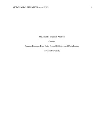
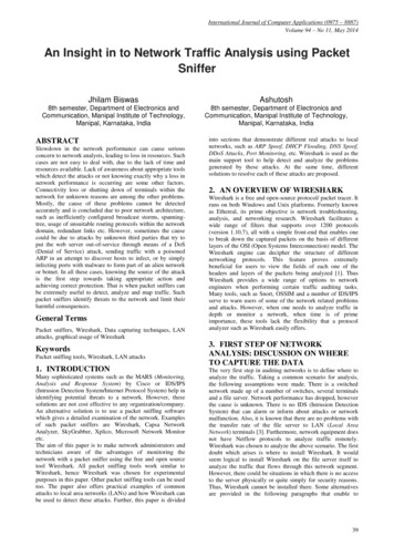
Network Analysis10ES34Practical sources:Network is a system with interconnected electrical elements. Network and circuit are the same.The only difference being a circuit shall contain at least one closed path.Electrical ement)N.E AAIkixBTUDBCurrent Source(ideal)ENVoltage Source(ideal)(a)gvx kvx-(b)(c) vix(d)(a)Current controlled current source(b) Voltage controlled current source(c) Voltage controlled voltage source(d) Current controlled voltage sourceN(Source quantity is determined by a voltageor current existing at someother Location in the circuit)These appear in the equivalent models for manyelectronic devices like transistors, OPAMPS andintegrated circuits.CITSM(Value of sourceQuantity is not affectedin anyway by activitiesin the reminder of thecircuit.)LC(Energy storing(Energystoringelement in amagnetic field) element in anElectric field)TS.INIndependentSourcesMPassive ElementsCITSTUDENTS.IN7
Network Analysis10ES34Voltage controlled current sourcegV1Node (Junction)C1Ki1i1Mesh (loop)LoopTYPES OF NETWORKSPractical TS.INECurrent controlledVoltage sourceTUDLinear and Nonlinear Networks:A network is linear if the principle of superposition holds i.e if e1(t), r1 (t) and e2(t),r2 (t) are excitation and response pairs then if excitation is e1 (t) e2 (t) then the response is r1 (t) r2(t).The network not satisfying this condition is nonlinearEx:- Linear – Resistors, Inductors, Capacitors.TSNonlinear – Semiconductors devices like transistors, saturated iron core inductor,capacitance of a p-n function.CIPassive and active Networks:A Linear network is passive if (i) the energy delivered to the network is nonnegativefor any excitation. (ii) no voltages and currents appear between any two terminals before anyexcitation is applied.Example:- R,L and C.Active network:- Networks containing devices having internal energy –Generators,amplifiers and oscillators.Unilateral & Bilateral:The circuit, in which voltage current relationship remains unaltered with the reversalof polarities of the source, is said to be bilateral.Ex:- R, L & CIf V-I relationships are different with the reversal of polarities of the source, thecircuit is said to be unilateral.Ex:- semiconductor diodes.CITSTUDENTS.IN8
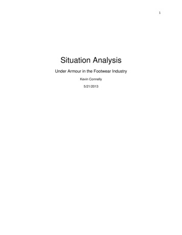
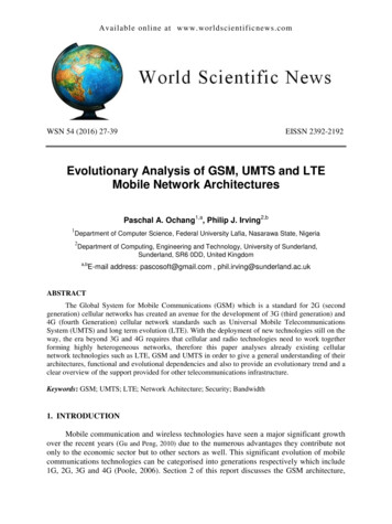
Network Analysis10ES34Lumped & Distributed:Elements of a circuit, which are separated physically, are known as lumpedelements.Ex:- L & C.Elements, which are not separable for analytical purposes, are known as distributedelements.Ex:- transmission lines having R, L, C all along their length.TS.INIn the former care Kirchhoff’s laws hold good but in the latter case Maxwell’s lawsare required for rigorous solution.Reciprocal:A network is said to be reciprocal if when the locations of excitation and responseare interchanged, the relationship between them remains the same.Source Transformation:ZSENIn network analysis it may be required to transform a practical voltage source into its equivalentpractical current source and vice versa . These are done as explained belowaZLISZPTUDESaZLbbfig 1fig 2Consider a voltage source and a current source as shown in Figure 1 and 2. For the sameload ZL across the terminals a & b in both the circuits, the currents arein fig 1TSIL ESZ s ZL.IL IS .Z Pin fig 2Z p ZLZPZ P ZLCIFor equivalence ES ISZS ZLTherefore ES IS Z P and ZS Z PandThereforeIS ESES ZPZSTransformation from a practical voltage source to a practical current source eliminates a node.Transformation from a practical current source to a current source eliminates a mesh.A practical current source is in parallel with an impedance Zp is equivalent to a voltage sourceEs Is Zp in series with Zp.A practical voltage source Es in series with a impedance Zs is equivalent to a current sourceEs/Zs in parallel with Zs.CITSTUDENTS.IN9
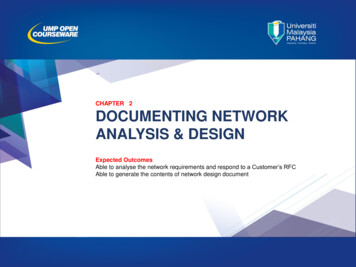
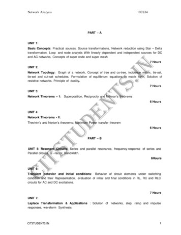
Network Analysis10ES34SOURCE SHIFTING:Source shifting is occasionally used to simplify a network. This situation arises because of the factthan an ideal voltage source cannot be replaced by a current source. Like wise ideal current sourcecannot be replaced by a voltage source. But such a source transformation is still possible if thefollowing techniques are fallowed.ccZ3Z1xTS.INaZ3 xZ2baZ1 E xEEN-EO--EZ2 bxOIZ2CIZ3IZ1Z1TSZ1TUD(a) E shift operationZ4Z4IZ2Z4Z2IZ3Z3II(b) I shift operationCITSTUDENTS.IN10
Network Analysis10ES34Sources with equivalent terminal characteristics V1 V2V1 V2V1 - V2 V1-v1 v2(i)Series voltage sourcesTS.IN(ii) Parallel voltage sources(ideal)i1i1i1i2i1 i2(iv)Series current sources(ideal)EN(iii) Parallel current sourcesi1 i2ZZ VzZTUD- V-I(v)Voltage source with parallel Z -ITSV(vi)Current source with series Z- VII(viii) V and I in SeriesCI(vii) V and I in Parallel V-IDelta-star transformation:A set of star connected (Y o:r T) immittances can be replaced by an equivalent set of mesh( or 7t) connected immittances or vice versa. Such a transformation is often necessary to simplifypassive networks, thus avoiding the need for any mesh or nodal analysis.For equivalence, the immittance measured between any two terminals under specifiedconditions must be the same in either case.CITSTUDENTS.IN11
Network Analysis10ES34 to Y transformation:Consider three -connected impedances ZAB, ZBC and ZCA across terminals A, B and C. It isrequired to replace these by an equivalent set ZA, ZB and ZC connected in star.AAZACZABZACCZCZBCZBBTS.INBIn , impedance measured between A and B with C open isZAB (ZBC ZCA)ZAB ZBC ZCAWith C open, in Y, impedance measured between A and B is ZA ZB.ZAB (ZBC ZCA)-----------(1)For equivalence ZA ZB ZAB ZBC ZCAENSimilarly for impedance measured between B and C with A open-----------------------------(2)ZB ZC ZBC (ZCA ZAB)ZAB ZBC ZCATUDFor impedance measured between C and A with B openZCA (ZAB ZBC)ZC ZA --------------------------------(3)ZAB ZBC ZCAAdding (1), (2) and (3)2 (ZA ZB ZC) (ZAB ZBC ZBCZCA ZCAZAB)ZAB ZBC ZCATSZA 2 (ZAB ZBC ZBCZCA ZCAZAB)ZAB ZBC ZCACISubstituting for ZB ZC from (2) ZA ZCA ZABZAB ZB ZCASimilarly by symmetryIfZCA- (ZB ZC)Z ABZ ABZB ZAB ZBCZABZC ZBC ZCAZABZAB ZBC ZCA Z!J then ZA ZB ZC ZY Z!J.3Y to A transformation:Consider three Y connected admittance Ya, Yb and Yc across the terminals A, B and C. It isrequired to replace them by a set of equivalent !J admittances Yab, Ybc and Yca.CITSTUDENTS.IN12
Network Analysis10ES34Admittance measured between A and B with B & C shortedYA (YB YC)YA YB YCIn !JYAB YCAAAYACYABYACCYCYBCBFor equivalence YAB YCA TS.INIn YYBBYA (YB YC)YA YB YC-------------------------(1)ENAdmittance between B and C with C & A shortedYBC YAB YB (YC YA) ------------------------------------(2)YA YB YCYAB TUDAdmittance between C and A with A & B shortedYC (YA YB) ---------------------------------(3)YCA YBC YA YB YCYAYB YBYC YCYAAdding (1), (2) and (3) YAB YBC YCA YA YB YC YA YB- (YBC YCA) YAsubstituting from (3)CITSYA YBYA YBYB YC: YBC : YCA Y YB YCAYA YB YCYA YB YCIn terms of impedances,ZA ZB ZBZC ZCZAZAB YA YB YC ZCYA YBZ Z ZBZC ZCZASimilarly ZBC A BZAZA ZB ZBZC ZCZAZCA ZBIf ZA ZB ZC ZY then ZAB ZBC ZCA Z!J 3ZY . CITSTUDENTS.IN13
Network Analysis10ES34Assignment questions:TS.IN1) Distinguish the following with suitable examples.i) Linear and non-linear elements.ii) Unilateral and trilateral elements.iii) Independent and dependent sources.2) Write the mesh equation for the circuit shown in Fig. 1 and determine mesh currents usingmesh analysis.Fig. 1TUDEN3) Establish star – delta relationship suitably4) Using source transformation, find the power delivered by the'50 V voltage sourcein the circuit shown in Fig.CITS5) Find the power delivered by the 5A current source in the circuit shown in Fig.4 by using thenodal method.CITSTUDENTS.IN14
Network Analysis10ES346) For the network shown in fig. 2, determine the voltage V using source shift and / or sourceTS.INtransformation techniques only. Then verify by node equationsTUDEN7) Use mesh current method to determine the current in the capacitor of 6Ω of the bridge networkshown in fig. 5.8) Use node equations to determine what value of ‘E’ will cause Vx to be zero for the networkCITSshown in fig. 6.CITSTUDENTS.IN15
Network Analysis10ES34TS.IN9) Obtain the delta connected equipment of the network shown in fig. 1.EN10) c) Find the voltage across the capacitor of 20 Ω reactance of the network shown in fig. 2, byreducing the network to contain one source only, by source transf
“Network Analysis”, M. E. Van Valkenburg, PHI / Pearson Education 2. “Networks and systems”, Roy Choudhury, 2 edition, New Age International Publications . 3. “Network theory “, Ganesh Rao. 4. “Net CITSTUDENTS.IN work analysis” , Roy Choudry. Network Analysis 10ES34 CITSTUDENTS.IN 5 1 2 Y 1 2. BASIC LAWS: 1. OHMS LAW V IZ A I AB Z B V I AB-Current from A to B V AB Voltage of .