Transcription
PHY 335 Modern Physics LabExperiment 1A:Speed of Light Measurement(Foucault Method)Jake AdkinsJosh OrzelKaitlin Vandemark
Objective The objective of this experiment was tomeasure the speed of light using the samemethod developed by the FrenchPhysicist, Jean Bernard Leon Foucault, in1862.
Theoretical Background The speed of light is one of the mostimportant constants of nature. After Einstein presented the Special Theoryof Relativity, it was established that the speedof light is an upper limit to the velocity of anyobject. Throughout history, there have been manyattempts to measure the speed of light, suchas those by Galileo, Rømer, Fizeau, andFoucault.
Theoretical Background Cont. In 1638, Galileo proposed having two covered lanternsat the tops of two hills, located about a mile apart. After one lantern is uncovered, the person holding thesecond lantern uncovers theirs. By measuring the time elapsed between the first personuncovering their lantern and when that person sees thesecond lantern, the speed of light could then becalculated by dividing twice the distance between themby the elapsed time. However, because of human reaction times and thegreatness of the speed of light, Galileo could onlydetermine that the speed was much greater than couldbe determined by use of his procedure.
Theoretical Background Cont. Rømer was the first to prove light has afinite speed.It is known that the moon would beeclipsed for the same amount of time.Because he noticed that the eclipseappeared to be longer when Earth wasmoving away from Jupiter than when itwas moving toward Jupiter, he attributedthis to the finiteness of the speed of light.Observations made between 1671–1673were the basis for his calculation.He calculated the speed of light to be2.1*10 8 m/s. (29% error)
Theoretical Background Cont. In 1829, Fizeau’s designed amethod consisted of a spinningwheel with slits. Light wouldtravel through a slit, bounce offof a mirror, and either passback through the same slit orget blocked by the next slit.Fizeau used specific values forthe distance between themirror and the wheel, thenumber of slits on the wheel,and the rate of rotation of thewheel to find the speed of light.The speed of light he foundwas 3.15*10 8 m/s (5% error)
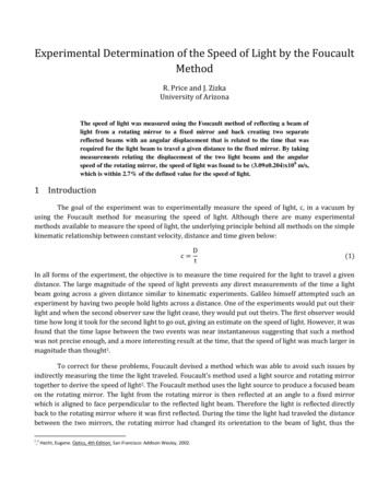
Theoretical Background Cont. Below is the Diagram for the FoucaultMethod showing the optical path of thelaser in the setup.
Setup
Setup Cont. A laser alignment bench and an optics bench are placedend-to-end. The laser is placed on the laser alignment bench. The rotating mirror, Mr, is placed on the end of the opticsbench opposite the laser. The laser is aimed such that the beam hits the center ofMr, by use of alignment jigs. Align the mirror such that the reflective side isperpendicular to the beam, thus reflecting the beam backtoward the laser. Place the first lens, L1, which has a focal length of 48mmso that it is aligned with the 93cm mark on the opticsbench. If necessary, move L1 relative to its holder toagain center the beam on the mirror.
Setup Cont. Place the second lens, L2, which has a focal length of 252mm sothat it is aligned with the 62.2cm mark. If needed, move the lensrelative to the holder to ensure that the beam is centered on Mr.Place the measuring microscope on the optics bench so that theright edge of the mounting stage is aligned with the 82cm mark. L2may need to be re-adjusted to center the beam again.Place the fixed mirror, Mf, 2-15m from Mr. The angle formedbetween the axis of the optics bench and a line connecting Mr andMf should be approximately 12 .Position Mr such that the beam is directed toward Mf. Then adjustthe position of Mf so that the beam strikes it approximately in thecenter.Place a piece of paper in front of Mf and slide L2 back and forthalong the optics bench to focus the beam to the smallest possiblepoint.Adjust the alignment screws on the back of Mf so the beam isreflected back to the center of Mr.
Setup Cont. Place the polarizers between the laser and L1.Start with the polarizers completely crossed,then rotate one until the image in themicroscope is bright enough to be visible. Bring the cross-hairs of the microscope intofocus by sliding the microscope eyepiece up anddown. Focus the microscope by loosening the lockscrew and sliding the scope up and down. Thepoint image should become visible. Focus untilthe image becomes as sharp as possible.
Procedure Turn the motor of Mr on so that it rotates in the clockwisedirection and increase the revolutions per second slowlyto 1000. Then, hold the button which causes the motorto reach its maximum rotational speed. Measure the corresponding deflection of the image pointby adjusting the micrometer knob on the microscope. After allowing the motor to come to rest, turn the motoron in the counter-clockwise direction and measure theresulting deflection after reaching the maximumrotational speed. This process is then repeated for 5-10 trials for threedifferent distances between Mr and Mf.
Parameters Laser used:– He-Ne source– 633nm wavelength– 4mW power
Derivation
Derivation Cont. To analyze our data we used the equation Where– C speed of light– A the distance between L2 and lens L1 minusthe focal length of L1– B the distance between lens L2 and Mr– D the distance between the Mr and Mf– s’ the location of the dot in the microscope.
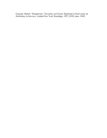
DataDistance OneD : 10mL1 : .9295mL2 : .6225mf1 : .048mM R : .135m .009145 .00850 1510 1514 .00914 .00850 1513 1515 .00914 .00852 1510 1515 .009138 .00850 1511 rev 1515 revs cw : ms: mw: w: ccw cw 1512 sccw 1514 s.00913.00850 .00913.0085015121514 .00914 .0085075 1513 1514 .009135 .0085025 1511 1515 2.91 108 2.937 108 8 3.028 10 284A 1 D ( wcw wccw ) 2.944 10 mcA : ( D B) ( s cw s ccw)8 s 2.981 10 82.981 10 8 2.97 10 8 2.969 10 ( )8mcmeanA : mean cA 2.965 10s
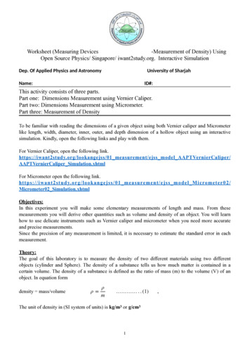
Data Cont.Speed of Light (m/s)Speed of light for Distance 13.2 1083 108ccA2.8 102.6 10880246x, t 1Trials810
Data Analysis 2.91 108 2.937 108 3.028 108 24A 1 D ( wcw wccw ) 2.944 108 mcA : ( D B) ( s cw s ccw)8 s 2.981 10 8 2.981 10 8 2.97 10 8 2.969 10 3.161 108 3.415 108 3.418 108 284A 2 D2 ( wcw2 wccw2 ) 3.289 10 mcB : s sD B( 2 2)( cw2 ccw2) 3.424 108 s 8 3.29 10 8 3.565 10 8 3.321 10 8m
Data Analysis Cont. 3.09 108 3.143 108 3.072 108 284A 3 D3 ( wcw3 wccw3 ) 3.118 10 mcC : (D3 B3)(s cw3 s ccw3) 3.145 108 s 8 3.1 10 8 3.151 10 8 3.115 10
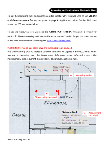
Data Analysis Cont.Speed of Light (m/s)Speed of Light for All Three TrialscA83 10cBcCc82 1081 1001020t1 , t2 , t3 , xTrials30
Data Analysis Cont.revδw : 1sδA : .05cmδB : .05cmδD : 1cmδs : .0000025m22222226mδcA : σA1 σB1 σD1 σwcw1 σwccw1 σscw1 σsccw1 1.784 10s22222226mδcB : σA2 σB2 σD2 σwcw2 σwccw2 σscw2 σsccw2 4.772 10s22222226mδcC : σA3 σB3 σD3 σwcw3 σwccw3 σscw3 σsccw3 1.381 10s
ResultsD : 10m8mcAfinal : 3.0 10s6m 1.8 10%error : cmeanA cc 1.094% sD : 4.5m8mcBfinal : 3.4 10s6m 4.8 10s%error2 : cmeanB cc 12.094% D : 14.44m8mcCfinal : 3.1 10s6m 1.4 10s%error3 : cmeanC cc 3.963 %
Error The best result (to within 5%) is obtained for a distanceof 10-15m. For the second trial, we used a distancemuch shorter than this, resulting in a proportionatereduction in accuracy. In the third trial, we used a distance which was greaterthan the radius of curvature of Mf, causing problems withthe focusing of the image point. The alignment of all of the components is very sensitive.Thus, because we likely did not have perfect alignment,this resulted in systematic error for each calculation ofthe speed of light. Furthermore, small changes in thealignment were likely made due to accidental bumps ofthe equipment during measurements, creating error inthe measurements following the misalignment.
Observations The fixed mirror, Mf, is sensitive to vibrations.Any jolts to the surface on which it rests resultsin the mirror becoming misaligned. It was necessary for our laser setup to be on thetable closer to the fume hood. Otherwise, wecould not get the angle to be correct. Also, thisstopped the laser beam from hitting anythingbetween Mr and Mf.
Conclusions The experiment was quite successful. Forthe shortest distance, we received a 12%error. However, because proportionalreduction in accuracy is expected forsmaller distances, this is fairly reasonable. For the other two distances, we had errorsof 1% and 3.9%, which both indicate goodmeasurements.
References Lee, Bruce. 1989. "Speed of LightApparatus". Physics 335 LaboratoryHandout. Cleveland State University, OH. "Rømer's Determination of the Speed of Light."Wikipedia, the Free Encyclopedia. Web. 09Feb. 2011. http://en.wikipedia.org/wiki/Rømer's determination of the speed of light . "Speed of Light." Wikipedia, the FreeEncyclopedia. Web. 09 Feb. 2011. http://en.wikipedia.org/wiki/Speed oflight .
Light would travel through a slit, bounce off of a mirror, and either pass back through the same slit or get blocked by the next slit. Fizeau used specific values for the distance between the mirror and the wheel, the number of slits on the wheel, and the rate of rotation of the wheel to find the speed of light. The speed of light he found