Transcription
Gasket Fabricators AssociationTechnical Handbook994 Old Eagle School Rd., Suite 1019, Wayne, Pennsylvania 19087-1802Phone: 610-971-4850Fax: 610-971-4859E-Mail: info@gasketfab.comWeb Site: www.gasketfab.com
Copyright 1998 -Gasket Fabricators Association994 Old Eagle School Road, Suite 1019Wayne, PA 19087-1866No duplication without the written consent of the Gasket Fabricators Association
Table of ContentsI IntroductionA.B.Gasket Fabricator Definition------------------------------ 1Types of Materials Fabricated - Processing Equipment-1IIStandard - 3A.B.C.D.E.F.G.H.Dimensional Characteristics------------------------------- 3Material Thickness Tolerances ---------------------------- -----------11Part -------12Labeling (Standard Label Format)------------------------ 13Lot ------- 14Quality Assurance ------------------------------------------ 15Statistical Process Control---------------------------------15
INTRODUCTIONGasket Fabricator Defined Types of MaterialFabricated—Processingaskets are an integral component of any device whichEquipmentGrequires the confinement of agas or liquid. They compensate for theunconformity of mating surfaces.These surface irregularities may beminute or large depending on thepurpose of the device but in all cases,the gasket is required to compensatefor the difference while limiting theflow of fluid in either direction.Gaskets differ from seals in thatgaskets are normally cut from sheets orrolls while seals are formed individually in their own configuration. A flatcut gasket is derived from material ofspecific thickness and to a configuration that is designed for a specificapplication.Organizations which convertmaterial in sheet or roll form to functional gaskets are designated as “gasketfabricators,” gasket cutters,” or simply“converters.” “Gasket fabricators” aregenerally perceived to be those organizations which have dedicated theirassets toward optimal accuracy andefficiency in their gasket fabricatingactivities. They have made major investments in sophisticated fabricating equipment. Gasket fabrication for originalequipment production line applicationsrequires consistency and precision on anever-improving scale. Organizations thatare sensitive to these needs, invest in therequired equipment and process controls.Members of the Gasket FabricatorsAssociation are professionals dedicatedto the continuous improvement ofthese activities.1If the gasket material is in sheet orroll form, a gasket fabricator canconvert it into parts. However,the material characteristics will determine the personality of the end product. Gasket materials that are hardand thin can be fabricated to tighterdimensional tolerances than gasketmaterials that are soft and thick.Accordingly, 90 durometer rubber 1 /32inch thick can be cut to more preciserequirements than 30 durometerrubber 1 /8 inch thick.Some gasket fabricators specialize in certain types of material. Onefabricator may have unique capabilities in the processing of sponge rubberproducts where another fabricatormay have acquired equipment moresuitable for elastomeric rubber.Another specialization is theability to process sheets rather thanroll goods. One fabricator may beheavily invested in platen presseswhile another may specialize in slittersand punch presses with continuousfeed and takeoff.Typical gasket fabricating equipment utilized by gasket fabricatorsare:1. Steel Rule Dies— Most commonly usedfor moderate volume parts. Tooling is economical and can be usedin platen presses, roll presses,mechanical presses or rotary diemachines.
2. Male and Female Blanking Dies—Generallyused in high volume productionwhere very close tolerances arerequired. Tooling is more costlybut generally longer lasting.3. Laser Cutting Machines—Laser technologyoffers excellent tolerance control withessentially no tooling wear. Equipment is expensive and used primarilyin very specific applications.4. Water Jet Cutting Machines—New technology with limited use, except inreinforced fiberglass compositecutting. Offers excellent tolerances.5. Wire Electrical Discharge Machines (EDM)—For small volume or prototypework. Very good for intricatedesigns.In summary, all gasket fabricatorsare not alike. They differ in their converting capabilities and accordingly, theydiffer in the types and forms of materials processed.2
STANDARD PRACTICESDIMENSIONAL CHARACTERISTICSGeneralThe objective of the followingspecifications and capabilitiesfor cut gaskets is to acquaint theuser of gasketing products with acceptable methods, procedures and dimensional characteristics used in the industry.The enclosed information and data isoffered as a guide to the designer ofgaskets as well as an aid to the purchasing facility using cut gaskets.The specifications outlined hereinwere developed from the present stateof the art with respect to known manufacturing techniques. Depending uponmaterials, product design and/orindividual manufacturing techniques,the dimensional specifications outlinedin the report may vary.Applicationn general, a gasket is used to sealtwo imperfect mating surfaces. Inany part designed as a gasket, onlythe designer knows which dimensionsare critical. If all are critical, thisshould be clearly indicated. In gasketdesigns, the bolt hole location and holesize are normally the most important.Port hole position and size may also beof prime concern. Thickness of thegasket as well as the material physicalcharacteristics play an important partin gasket design and capability. Theessential design elements shouldalways be specified on drawings. Inexamining a gasket drawing the producer of a gasket frequently questionsif corners must be as sharp as shownI3or whether radii are acceptable; do allholes and ports actually require thesame close tolerances; and does thetitle block tolerance properly reflectactual gasket requirements versusstandards for machined parts? Thedesigner should be certain he needseverything he specifies. Unnecessaryrequirements can result in needlesscosts in producing the parts. Consultation with the gasket fabricator willoften lead to cost saving in tooling orproduction of the part.MethodsAlthough cutting methods forindividual gaskets can varywidely, the most conventionalcutting tools used are: Steel rule dies,solid steel dies, or a combination ofboth. The most widely used is the steelrule die. Steel rule dies have beendescribed as “glorified cookie cutters.”A steel rule die consists of a basematerial such as high grade plywood orphenolic composition which becomesthe holder for a strip of hard thin steelsharpened on one edge known as “steelrule.” Sharpened hole punches knownas “tubes” are incorporated along withrubber stripper pads to complete thetool. Depending upon the dimensionalaspects of the part, different procedurescan be used in the construction of thecutting tool. These various methodsgreatly dictate the accuracy of the cutpart.The illustrations on page 7 and 8outline steel rule construction methods.
Tooling TypesThe two most common types oftooling used are steel rule dies and allsteel dies. Volume, quantity, tolerance,and cost are the variables that helpdetermine the type of tooling used.Steel Rule DiesThere are multiple ways to construct asteel rule die. However, the objective ofany method is to cut a pattern of the partinto the base material, and then insert asteel rule that has been bent into thesame pattern, into the base material.The various methods used tomake a steel rule die are:n To obtain the pattern cut into thedieboard, the customer’s print or partpattern can be either hand or machinedrafted onto the dieboard. Thedieboard is then hand cut with ajigsaw.n Another method is to program thecustomer’s print into a computercontrolled laser cutting machine andlaser cut the pattern into the dieboard.n Once the pattern is cut into thedieboard, the steel rule is bent into thesame pattern and inserted into theboard. The bending of the steel rulecan be done either by hand or by usinga computer driven rule bendingmachine.As shown in the chart on thefollowing page, these methods havedifferent tolerances associated withthem.and the die in all steel tooling. Thecommon practice is to construct allsteel tooling with minimum clearancebetween the punch and die. In manyinstances, the punch may be hard witha soft die which allows the die to be“peened” against the punch to providezero clearance conditions. Zero clearance provides clean cut parts. As theedges of the punch and die becomerounded due to the abrasive action ofthe material being cut, the quality ofthe cut part may diminish.Dimensional tolerancing for allsteel tooling can be controlled to a fewthousandths of an inch. The improvedaccuracy of all steel tooling over ruledie tooling results in more accuratepart dimensional capabilities. Althoughthe all steel tooling used to produce agasket may be built to very closetolerances, the tolerance of the partdepends upon the gasketing material.The material may pull or stretch duringthe cutting action. The cut part may besubject to shrinkage or expansiondepending on the atmospheric conditions after cutting. To maintain maximum dimensional stability on partsproduced from all steel tooling, the dieshould be maintained in a sharp condition and the parts should be packagedin a stable environment.All Steel ToolingDepending upon the complexityof the design, the type of material andthe volume of the part, all steel maleand female tooling is often used toproduce a gasket. Unlike blanking orcutting ferrous or nonferrous materials, most gasketing materials do notrequire clearance between the punch4
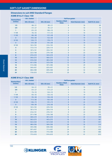
Dimensional Capabilities for Steel Rule DiesIt is important to know that the dimensions of the diecut part are determined not only by the die, but also bythe material type, hardness, density, thickness, andvariations of these factors. The greater the variation ofthese factors, the greater the variance of the die cut dimensions.Different types of tooling have different dimensionaltolerances.All steel tooling provides the most accurate tolerances.These can vary depending on type of tool constructionmethods, but generally /-.002 to /-.005 can be held.Steel rule tooling also varies with the type of construction method. The most accurate is laser cut board withautomated bent rule. Depending on length of rule, tolerances can range from /-.005 to /-.015. The longer the ruleis, the more variation can be expected.Steel rule dies that are laid out by hand and jigsaw cutcan not be held this tight and will generally vary /-.030.Holes that are cut using punches will have the sametolerance regardless of die construction method. Theindustry accepted variation on punch dimensions are asfollows:Hole diameter—less than 3 /4 ” /-.00235Hole diameter—from /4”-1 / 8 /-.003Hole diameter—greater than 15 / 8 /-.005Hole position tolerance is again best achieved usinglaser cutting and automated rule bending. Depending ondistance between holes /-.005 to /-.015 can be expected. Ifthe die is laid out by hand and jigsaw cut, the tolerancescould be /-.010 to /-.030.These tolerances are general guidelines and can varybased upon die building equipment and the skills of the diemaker.5
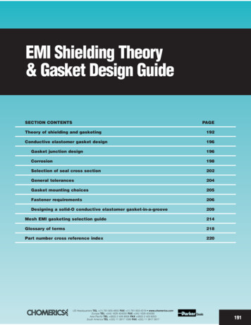
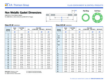
Steel Rule Die Making MethodsThe die making process begins with the layout. The layout can bedone either manually or by C.A.D.A computer controlled laser cutsthe die board.The pattern is cut with a precision jig saw.6
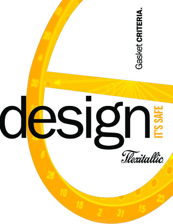
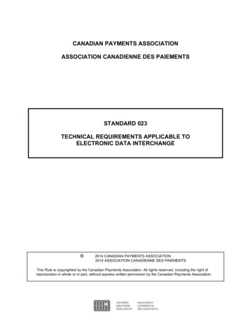
The steel rule ishand cut and bentto proper configuration.(Right) A computer controlledmachine cuts andbends the rule.The steel rule is inserted into thedie board.The steel rule die is complete.7
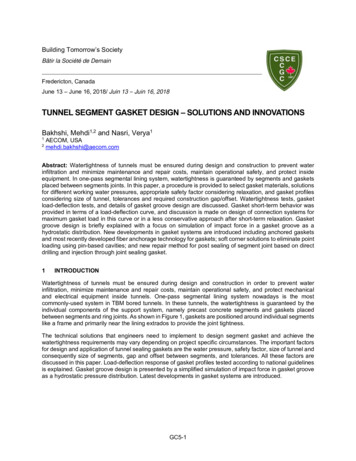
Dimensional VerificationVarious methods are used to check dimensions onproduction tooling or parts. In most cases, it is difficult tomeasure the dimensions on the steel rule die itself, becauseof the many types of bevels and position of the cutting edge.Single Bevel Double BevelSingleDoubleBevelDoubleDouble BevelCreasingRuleIt is not recommended to use the gasket as a measuringdevice since the part is usually flimsy and unstable. Somegasket materials are subject to change due to atmosphericconditions, such as humidity.Die impressions are commonly used to check dimensions. The impression should be made on stable material.These materials are not subject to change due to temperature or moisture conditions. Mylar, plastics and tag paperare commonly used. An impression is created by eithercutting partially into the plastic material, which gives a cleardefined line to measure against, or a dark line impressioncan be obtained by placing carbon paper between the dieand manila tag. If a coordinate measuring machine is usedfor checking, the plastic impression is best to use since adefined line is present in which to position the stylus. Caution should be used when making the impression. Distortioncan result if the impression is too deep which can causeerrors in measurement.Manila tag impressions can be easily measured usingstandard drafting techniques or they can be used withcoordinate measuring machines similar to plastic impressions.Punched holes dimensions should be measured bymeans of plug gauges in the punched hole of the gasket.The hole should be measured opposite the initial piercedside. On relatively thin materials, there will be little, if any,size variation from one side or the other. On thick materials, the bevel of the punch tube may distort the hole to somedegree.Hole true position can best be determined by coordinate measuring machines. All positional tolerance requirements are to be based upon maximum material conditions(MMC) unless otherwise specified.An example of hole location tolerance for floatingfasteners and tolerances for radius with an unlocated centeris illustrated at the top of the next page.8
To
materials, product design and/or individual manufacturing techniques, the dimensional specifications outlined in the report may vary. ApplicationI n general, a File Size: 354KBPage Count: 19