Transcription
POWER AVAILABILITYUPStation GXT 2U USER MANUAL500-3000VA120V
TABLE OF CONTENTS1.0GLOSSARY OF SYMBOLS . . . . . . . . . . . . . . . . . . . . . . . 32.0INTRODUCTION . . . . . . . . . . . . . . . . . . . . . . . . . . . . . . . 43.0MAJOR COMPONENTS . . . . . . . . . . . . . . . . . . . . . . . . . 53.1Transient Voltage Surge Suppression (TVSS)and EMI/RFI Filters. . . . . . . . . . . . . . . . . . . . . . . . . . . . . 53.2Rectifier/Power Factor Correction (PFC) Circuit . . . . . . 53.3Inverter . . . . . . . . . . . . . . . . . . . . . . . . . . . . . . . . . . . . . . . 53.4Battery Charger . . . . . . . . . . . . . . . . . . . . . . . . . . . . . . . . 63.5DC to DC Converter . . . . . . . . . . . . . . . . . . . . . . . . . . . . . 63.6Battery . . . . . . . . . . . . . . . . . . . . . . . . . . . . . . . . . . . . . . . 63.7Dynamic Bypass . . . . . . . . . . . . . . . . . . . . . . . . . . . . . . . . 63.8GXT 2U (Rear View). . . . . . . . . . . . . . . . . . . . . . . . . . . . . 74.0INSTALLATION . . . . . . . . . . . . . . . . . . . . . . . . . . . . . . . 84.1Preparation . . . . . . . . . . . . . . . . . . . . . . . . . . . . . . . . . . . . 84.2Tower UPS Installation . . . . . . . . . . . . . . . . . . . . . . . . . . 84.3Rack-Mount UPS Conversion and Installation . . . . . . . 94.4External Battery Cabinet Installation . . . . . . . . . . . . . 135.0CONTROLS AND INDICATORS . . . . . . . . . . . . . . . . . . . 145.1ON/Alarm Silence/Manual Battery Test Button . . . . . 145.2Standby/Manual Bypass Button . . . . . . . . . . . . . . . . . . 155.3Load/Battery Level Indicators (4 Green, 1 Amber) . . . 155.4Fault Indicator LED (Red) . . . . . . . . . . . . . . . . . . . . . . . 155.5Bypass Indicator LED (Amber) . . . . . . . . . . . . . . . . . . . 155.6UPS ON Indicator LED (Green) . . . . . . . . . . . . . . . . . . 155.7Battery Indicator LED (Amber). . . . . . . . . . . . . . . . . . . 155.8AC Input Indicator LED (Green). . . . . . . . . . . . . . . . . . 165.9Output Voltage Selection . . . . . . . . . . . . . . . . . . . . . . . . 16i
6.0OPERATING INSTRUCTIONS . . . . . . . . . . . . . . . . . . . . 176.1Normal Mode Operation . . . . . . . . . . . . . . . . . . . . . . . . 176.2Bypass Mode Operation . . . . . . . . . . . . . . . . . . . . . . . . . 176.3Battery Mode Operation . . . . . . . . . . . . . . . . . . . . . . . . 186.4Battery Recharge Mode . . . . . . . . . . . . . . . . . . . . . . . . . 187.0COMMUNICATIONS . . . . . . . . . . . . . . . . . . . . . . . . . . . 197.1Communications Interface Port. . . . . . . . . . . . . . . . . . . 197.2Pins 4 & 5 - Remote Shutdown on Battery . . . . . . . . . . 207.3Pins 5 & 6 - Any-Mode Shutdown . . . . . . . . . . . . . . . . . 217.3.17.3.2Auto-Enable Output . . . . . . . . . . . . . . . . . . . . . . . . . . 21Pin 6 Logic . . . . . . . . . . . . . . . . . . . . . . . . . . . . . . . . . . 217.4UPS Intelligent Communications . . . . . . . . . . . . . . . . . 228.0CONFIGURATION PROGRAM . . . . . . . . . . . . . . . . . . . . 238.1GXT 2U Configuration Program Abilities. . . . . . . . . . . 238.1.1What You Will Need . . . . . . . . . . . . . . . . . . . . . . . . . . 239.0MAINTENANCE . . . . . . . . . . . . . . . . . . . . . . . . . . . . . . 249.1Battery Replacement . . . . . . . . . . . . . . . . . . . . . . . . . . . 249.1.1Internal Battery Replacement Procedures . . . . . . . . 259.2Fuse Replacement . . . . . . . . . . . . . . . . . . . . . . . . . . . . . 2610.0TROUBLESHOOTING . . . . . . . . . . . . . . . . . . . . . . . . . . 2711.0SPECIFICATIONS . . . . . . . . . . . . . . . . . . . . . . . . . . . . 3212.0BATTERY CABINET SPECIFICATIONS . . . . . . . . . . . . . . 3413.0BATTERY RUN TIMES . . . . . . . . . . . . . . . . . . . . . . . . . 3514.0PRODUCT WARRANTY REGISTRATION. . . . . . . . . . . . . 36TABLESTable 1Table 2Troubleshooting guide . . . . . . . . . . . . . . . . . . . . . . . . . . . . 28Alarm conditions . . . . . . . . . . . . . . . . . . . . . . . . . . . . . . . . . 31ii
IMPORTANT SAFETY INSTRUCTIONS!WARNINGOpening or removing the cover may expose you to lethalvoltages within this unit even when it is apparently notoperating and the input wiring is disconnected from theelectrical source. Observe all cautions and warnings in thismanual. Failure to do so MAY result in serious injury ordeath. Refer all UPS and battery service to qualified servicepersonnel. Do not attempt to service this product yourself.Never work alone.SAVE THESE INSTRUCTIONSThis manual contains important safety instructions. Read all safety,installation, and operating instructions before operating the Uninterruptible Power System (UPS). Adhere to all warnings on the unit andin this manual. Follow all operating and user instructions. Individualswithout previous training can install and operate this equipment.It is not intended for use with life support and other designated “critical” devices. Maximum load must not exceed that shown on the UPSrating label. The UPS is designed for data processing equipment. Ifuncertain, consult your local dealer or Liebert representative.This UPS is designed for use on a properly grounded (earthed), 50Hzor 60Hz, 120V supply (programmable for 100, 110, 115, 120 and127VAC output). Installation instructions and warning notices arelocated in this manual.ELECTROMAGNETIC COMPATIBILITY—The GXT 2U Seriescomplies with the limits for a CLASS A DIGITAL DEVICE, PURSUANT TO Part 15 of FCC rules. Operation is subject to the followingtwo conditions: (1) This device may not cause harmful interference,and (2) this device must accept any interference received, includinginterference that may cause undesired operation. Operating thisdevice in a residential area is likely to cause harmful interference thatusers must correct at their own expense.Operate the UPS in an indoor environment only in an ambient temperature range of 32 F to 104 F (0 C to 40 C). Install it in a cleanenvironment, free from moisture, flammable liquids, gases and corrosive substances.1
This UPS contains no user serviceable parts except the internal battery pack. The UPS ON/Standby push buttons do not electrically isolate internal parts. Under no circumstances attempt to gain accessinternally other than to replace the batteries due to risk of electricshock or burn. Do not continue to use the UPS if the front panel indications are not in accordance with these operating instructions or ifthe UPS performance alters in use. Refer all faults to your localdealer, Liebert representative or the Liebert Worldwide SupportGroup.Servicing of batteries should be performed or supervised by personnelknowledgeable of batteries and the required precautions. Keep unauthorized personnel away from the batteries. PROPER DISPOSAL OFBATTERIES IS REQUIRED. REFER TO YOUR LOCAL LAWS ANDREGULATIONS FOR BATTERY DISPOSAL REQUIREMENTS.Never block or insert any object into the ventilation holes or otheropenings of the UPS.DO NOT CONNECT equipment that could overload the UPS ordemand half-wave rectification from the UPS, for example: electricdrills, vacuum cleaners, laser printers or hairdryers.Storing magnetic media on top of the UPS may result in data loss orcorruption.Turn the UPS off and isolate the UPS before cleaning; use only a softcloth, never liquid or aerosol cleaners. Keep the front and rear ventsfree of dust accumulation that could restrict airflow.When replacing batteries, replace with the same Liebert authorizedreplacement battery kits.!CAUTIONDo not dispose of battery or batteries in a fire. The batterymay explode.Do not open or mutilate the battery or batteries. Releasedelectrolyte is harmful to skin and eyes. It may be toxic.!CAUTIONA battery can present a risk of electrical shock and high shortcircuit current. The following precautions should be observedwhen working on batteries: Remove watches, rings, and other metal objects. Use tools with insulated handles.2
Glossary of Symbols1.0GLOSSARY OF SYMBOLSRisk of electrical shockIndicates caution followed by important instructionsAC inputAC outputiRequests the user to consult the manualIndicates the unit contains a valve-regulated lead acidbatteryRecycleDC voltageEquipment grounding conductorBonded to groundAC voltageONStandby3
Introduction2.0INTRODUCTIONCongratulations on your choice of the Liebert UPStation GXT 2U Uninterruptible Power System (UPS). It provides conditioned powerto microcomputers and other sensitive electronic equipment.Upon generation, AC power is clean and stable. However, duringtransmission and distribution it may be subject to voltage sags,spikes, or complete power failure that may interrupt computer operations, cause data loss, or even damage equipment. The UPStationGXT 2U protects equipment from these disturbances.The UPStation GXT 2U comes in nominal power ratings of 500, 700,1000, 1500, 2000 and 3000 VA. Complete model specifications appearat the end of this manual.The UPStation GXT 2U is a compact, “on-line” UPS. An on-line UPScontinuously conditions and regulates its output voltage, whether utility power is present or not. It supplies connected equipment withclean sinewave power. Sensitive electronic equipment operates bestfrom sinewave power.For ease of use, the UPStation GXT 2U features a light-emitting diode(LED) display to indicate either load percentage or battery capacitydepending upon the mode of operation. It also provides self-diagnostictests, a combination ON/Alarm Silence/Manual Battery Test button, aStandby button, user configurable program, and two levels of alarmswhen the unit is operating on battery.The UPStation GXT 2U has an interface port for communicationbetween the UPS and a network server or other computer systems.This port provides detailed operating information including voltages,currents, and alarm status to the host system when used in conjunction with Liebert MultiLink software. MultiLink software can alsoremotely control UPS operation.4
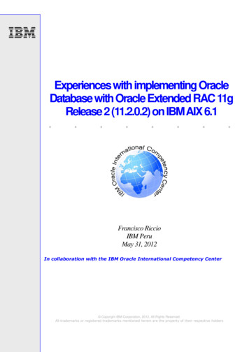
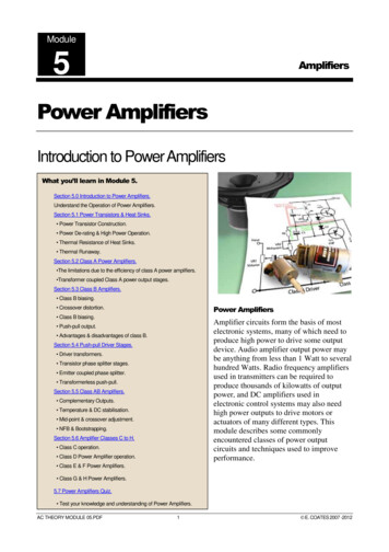
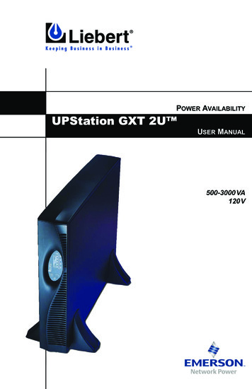
Major Components3.0MAJOR COMPONENTSInputL1OutputDynamicBypassTVSS &EMI/RFIFiltersRectifier/PFCInverterL1DC to DCConverterBatteryChargerBatteryL2L2GG3.1TRANSIENT VOLTAGE SURGE SUPPRESSION (TVSS)AND EMI/RFI FILTERSThese UPS components provide surge protection and filter both electromagnetic interference (EMI) and radio frequency interference(RFI). They minimize any surges or interference present in the utilityline and keep the sensitive equipment protected.3.2RECTIFIER/POWER FACTOR CORRECTION (PFC) CIRCUITIn normal operation, the rectifier/power factor correction (PFC) circuitconverts utility AC power to regulated DC power for use by theinverter while ensuring that the waveshape of the input current usedby the UPS is near ideal. Extracting this sinewave input currentachieves two objectives: The utility power is used as efficiently as possible by the UPS. The amount of distortion reflected on the utility is reduced.This results in cleaner power being available to other devices in thebuilding not being protected by the UPStation GXT 2U.3.3INVERTERIn normal operation, the inverter utilizes the DC output of the powerfactor correction circuit and inverts it into precise, regulated sinewaveAC power. Upon a utility power failure, the inverter receives itsrequired energy from the battery through the DC to DC converter. Inboth modes of operation, the UPS inverter is on-line and continuouslygenerating clean, precise, regulated AC output power.5
Major Components3.4BATTERY CHARGERThe battery charger utilizes energy from the utility power and precisely regulates it to continuously “float charge” the batteries. The batteries are being charged whenever the UPStation GXT 2U is pluggedin, even when the UPS is not turned on.3.5DC TO DC CONVERTERThe DC to DC converter utilizes energy from the battery system andraises the DC voltage to the optimum operating voltage for theinverter. This allows the inverter to operate continuously at its optimum efficiency and voltage, thus increasing reliability.3.6BATTERYThe UPStation GXT 2U utilizes valve-regulated, nonspillable, flameretardant, lead acid batteries. To maintain battery design life, operatethe UPS in an ambient temperature of 68 F to 77 F (20 C to 25 C).Optional external battery cabinets are available to extend battery runtimes.3.7DYNAMIC BYPASSThe UPStation GXT 2U provides an alternate path for utility power tothe connected load in the unlikely event of a UPS malfunction. Shouldthe UPS have an overload, overtemperature, or UPS failure condition,the UPS automatically transfers the connected load to bypass. Bypassoperation is indicated by an audible alarm and illuminated amberBypass LED (other LEDs may be illuminated to indicate the diagnosed problem). To manually transfer the connected load from theinverter to bypass, press the Standby button once.NOTEThe bypass power path does NOT protect the connectedequipment from disturbances on the utility supply.6
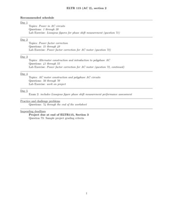
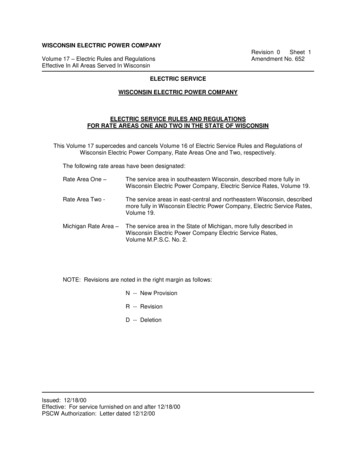
Major Components3.8GXT 2U (REAR VIEW)Intellislot PortDB-9Communications PortCooling FanExternal BatteryConnectorInput Fuse/CircuitBreakerOutputReceptaclesAC InputSupport Base7
Installation4.0INSTALLATION4.1PREPARATION1. Visually inspect the UPS for freight damage. Report damage tothe carrier and your local dealer or Liebert representative.!CAUTIONThe UPS is heavy (see 11.0 - Specifications). Take properprecautions when lifting or moving it.2. Decide where to place the GXT 2U. Install the UPS indoors in acontrolled environment, where it cannot be accidentally turned off.Place it in an area of unrestricted airflow around the unit, awayfrom water, flammable liquids, gases, corrosives, and conductivecontaminants. Maintain a minimum clearance of 4 in. (100mm) inthe front and rear of the UPS. Maintain an ambient temperaturerange of 32 F to 104 F (0 C to 40 C).NOTEUPS operation in temperatures above 77 F (25 C) reducesbattery life.3. The GXT 2U may be installed in either a tower configuration or ina rack, depending on available space and use considerations.Determine the type of
uncertain, consult your local dealer or Liebert representative. This UPS is designed for use on a properly grounded (earthed), 50Hz or 60Hz, 120V supply (programmable for 100, 110, 115, 120 and 127VAC output). Installation instructions and warning notices are located in this manual. ELECTROMAGNETIC COMPATIBILITYŠThe GXT 2UŽ Series