Transcription
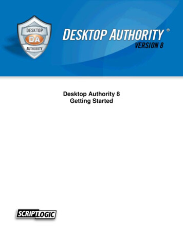
Installation guideXS4 ControllerEngEFCU4EB8Installation guide104(4-1/8")44(1-3/4")Guía de instalaciónGuide d'installationThe expansion board unit provides multi-relayswitchable output management to externalsystems such as lift floor level access,multi-shutter and barrier systems, machineswitching and more.43(1-11/16")Model: DC Input600gONGND12VDC Output (1A)READER 1GNDAB -BUS485READER 2TAMPERIN1RL1IN2IN3IN4RL2RL3IN5IN6RL4BABA -226gPower Input: 12V DC-1A -TX10(3/8")Ø 4 2")(5/3EngMechanical Installation12EInstalación mecánicaFInstallation mécanique3CU4EB8TCU4EB8G*TAMPER*Note: In order to comply withEN 50131-3:2009, the twohighlighted openings can't beused.CU4EB8Connect!Note: Follow the same connection model, using the CU tamper input, when using a third party electric box equipped with atamper opening detection.All contents current at time of publication.SALTO Systems S.L. reserves the right to change availability of anyitem in this catalog, its design, construction, and/or materials.XS4 Controller 2020 SALTO Systems S.L.225205- 1/10 -ED1. 12/02/2021
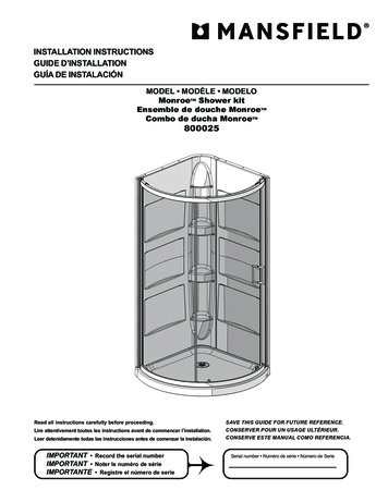
Installation guideXS4 ControllerEng12connected at the end of the BUS.1Model:8CU4EB834Model: CU4EB85Power Input: 12VDC-500mA312VDC Input412VDC Output (1A)ONGNDIN2GND510AB 6RL3RL7RL4RL86 -IN1778NCCNONCCNONCCNONCCNO6F13El pulsador del Tamper, está conectado en paralelo con la2Resistor del terminal BUS RS485 tiene que estar en la posición5ON cuando la CU4EB8 esté al final del BUS.64entrada de tamper.Contacteur anti sabotage monté en parallèle avec l’entrée antisabotage.La résistance de fin de bus RS485 est nécessaire (position ON) lorsquela CU est positionnée à l'extrémité du bus.Entrée Alimentation.Sortie Alimentation:Cette sortie est reliée directement au port d'entréede l'alimentation protégée par un fusible de 1A.Entrada de alimentación.4 Salida alimentada: esta salida se conecta directamente a3la entrada de alimentación protegida por un fusible de 1A.BUS485.6 Conexiones relés: tener en cuenta las restricciones de759restrictions(2A-30VDC). Use the provided varistor if an inductive load isused.Inputs: Installer must identify the bridge cable needed depending onthe input configuration.Online/Offline jumper:Configure the unit to work as an offline device.Dip switch:Offline Mode- See output table to assign the output number to a relay.10 Tamper input to connect the tamper signal from the SALTO electric boxor other compatible devices.18BUS485.Relay Connections: Please take into account the max. load927Power Input.Power Output: This output is directly connected to the power Input portprotected by a 1A fuse.92EPhysical tamper switch to be operated by external electric box models.BUS RS485 Terminal Resistor must be in the ON position when the CU is8carga (2A-30VDC). Utilice el varistor suministrado si la cargaes de tipo inductivo.Entradas: el instalador ha de identificar el cable para elpuente dependiendo de la configuración de la entrada.Jumper Online/Offline: configure la unidad para trabajar enmodo offline.9BUS485.Connexion des relais:S'il vous plaît prendre en compte les restrictions decharge max. (2A-30VDC). Utilisez les varistances fournis si une chargeinductive est utilisée.Entrées:L'installateur doit identifier le câble nécessaire en fonction de laconfiguration d'entrée.Cavalier Online/Offline:Indique si l'unité fonctionne en tantqu'équipement Offline.Dipswitch:Mode Offline- Voir la table des sorties pour assigner aux relais leurnuméro de sortie.Dip switch:Modo offline- Diríjase a la tabla de salidas para asignar elnúmero de salida al relé.Factory configuration (offline tput number 1RL2Output number 2RL3Output number 3RL4Output number 4RL5Output number 5RL6Output number 6RL7Output number 7RL8Output number 8EngConfiguración de fábrica (modo litadaIN4DeshabilitadaRL1Salida número 1RL2Salida número 2RL3Salida número 3RL4Salida número 4RL5Salida número 5RL6Salida número 6RL7Salida número 7RL8Salida número 8Configuration d'usine (Mode IN4DésactivéRL1Sortie numéro 1RL2Sortie numéro 2RL3Sortie numéro 3RL4Sortie numéro 4RL5Sortie numéro 5RL6Sortie numéro 6RL7Sortie numéro 7RL8Sortie numéro 8Electrical characteristics:Operation conditionsMinTemperature umptionOutputportcurrent Note 2Nom.12MaxOutputrelaysUnitUnit5v Note 3ViaSoftware Note 4Cable recommendationV1500 Note11All contents current at time of publication.SALTO Systems S.L. reserves the right to change availability of anyitem in this catalog, its design, construction, and/or materials.mAABUS485Twisted pair AWG24InputsAWG24XS4 Controller 2020 SALTO Systems S.L.Ratedload(resistive)2A-30VdcNote 1:This is the maximum consumption ofthe CU4EB8 using the output power port(1A max). If the power output port is notused, the maximum consumption is 500mANote 2:Same voltage as the input.Note 3:1K pull-up resistor.Note 4:See the software User Manual.225205- 2/10 -ED1. 12/02/2021
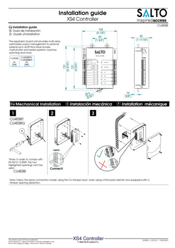
Installation guideXS4 ControllerCaracterísticas Electricas:ECondiciones ambientalesMinTypTemperatura 025Humedad35EntradaMax6085Relés de ón5v Nota 3Carga (resistiva)ViaSoftware Nota 4PotenciaMinVoltageConsumo dela corrienteSalidaCorriente Nota 2Nom.12MaxUnitCable recomendadoV1500Nota 11mABUS485AInputsAWG24 par trenzadoCondition de fonctionnementMinTypTempérature 025Humidité35AWG24EntréeMax6085Relais de ationCharge nominal (résistive) 2A - 30Vdc5v Note 3ViaSoftware Note 4PuissanceMinTension d’entréeCourantde consommationCourant en sortiedu bornier Note 2Nom.12MaxUnitéType de câbleV1500 Note 11EInstallation example:Ejemplo de instalación:FExemple d’installation:EngmABus d’extensionAEntréePaire torsadée AWG24AWG24Model:Power Input: 12VDC -CU4EB8500mABUS485IN3TAMPERIN4 -12VDC InputONGND12VDC Output (1A)GNDAB NCCNCNOCRL4RL8NC2Offline configurationThe unit must be connected to aCU4200 in stand alone mode(dip-switch in the CU4200 - 0000).In offline mode, the inputs aredisabled.12OFFLINE4The dip-switch configures thenumber of the output in thedifferent relays as the followingtable.To assign the output number to aspecific user see SALTO ProAccessSPACE User Manual.All contents current at time of publication.SALTO Systems S.L. reserves the right to change availability of anyitem in this catalog, its design, construction, and/or materials.34La unidad debe ser conectada auna CU4200 en modo autónomo(dip-switch en CU4200 - 0000).En modo offline, las entradasestán deshabilitadas.Los dip-switch se utilizan paraconfigurar el número de la salidaen los diferentes relés según latabla siguiente.Diríjase al manual de usario deSALTO ProAccess SPACE paraasignar el número de salida a unusuario específico.XS4 Controller 2020 SALTO Systems S.L.1 Electric Strike1 Cerradero eléctrico1Gâche électriqueNONCCNOConfiguración offlineEONLINE3Note 1: Ceci est la consommation maximalede la CU4EB8 lorsque le bornier de sortiealimentation (1A max) est utilisé. Si le bornierde sortie alimentation n'est pas utilisé, laconsommation maximum est 500mA.Note 2: Memem tension que l'entrée.Note 3: Résistance de pull-up 1K.Note 4: Consultez le manuel du logicielutilisateur.Model: CU4EB812Vdc1Nota 1:Este es el consumo máximo de laCU4EB8 utilizando el conector de salida (1Amáx). Si el conector de salida no se usa, elconsumo máximo es de 500mA.Nota 2:Misma tensión que en la entrada.Nota 3:Resistencia de 1K.Nota 4:Ver manual de usuario del software.Caractéristique électrique:FEng2A-30VdcF12OFFLINEConfiguration OfflineL'appareil doit être connecté à uneCU4200 en mode autonome(dip-switch du CU4200 - 0000).En mode offline, les entrées sontdésactivées.OFFLINEONLINEONLINE34Le dip-switch configure le numérode sortie des différents relais enfonction du tableau suivant.Pour attribuer un numéro de sortie àun usager particulier voir le Manueld'utilisation de SALTO ProAccessSPACE.225205- 3/10-ED1. 12/02/2021
Installation guideXS4 ControllerTABLE 1/TABLA 1/ TABLEAU 6474801011011TABLE 2/TABLA 2/ TABLEAU 2Eng123Online Configuration:Connect all the devices through the BUS485and powerthe CU4EB8.Create and set up the CU4EB8 on the Software(Consult the SALTO ProAccess SPACE user manual).- Asign the CU4EB8 to the node it is connected.- Define the address in the BUS485.- The relay out set up has to be done through the SALTOProAccess SPACE software.OFFLINEPut the Resistor in ONLINE mode.ONLINE- The CU4EB8 dip-switch setting is used togive each device on the BUS485 a uniqueaddress.- Ensure that the address in the software is the same asthe one you put on the hardware. (See Table 2).- Both ends of the BUS485 must have the RS485BUStermination resistor in the ON position, intermediatedevices need to have the resistor in OFF position.Supervised input connections:By default all inputs are disabled.They can be configured throughR1the software. If the inputs are supervised,the resistance value R1 and R2 aredefined in the software:1k (recommended),1k5,2k2,3k3,4k7,6k8,10k.R1 R2E123ADDRESSAddress 1Address 70001Address 20010Address 31110Address 4Address 1511111001Address 1010100101Address 111011Address 6Hacer todas las conexiones físicas de la red (BUS485) yalimentar la CU4EB8.Dar de alta la CU4EB8 en el Software (consultar el manualde usuario de SALTO ProAccess SPACE).- Asignar el nodo al que se va a conectar.- Definir la dirección en el BUS485.- La configuración de las salidas de los relés ha de hacersea través del software SALTO ProAccess SPACE.Poner el jumper en modo ONLINE.- El dip-switch de la CU4EB8 se usa para asignarle unadirección dentro del BUS485.Esta dirección ha de ser la misma que la asignada en elsoftware. Ver tabla 2.- Ambos extremos del BUS485 han de tener la resistencia delterminal en posición On, y el resto de CU4EB8 han detener esta resistencia en posición OFF.Address 14Address 9Address 5R2Address 13Address 810000011ADDRESS110101110100Configuración online:All contents current at time of publication.SALTO Systems S.L. reserves the right to change availability of anyitem in this catalog, its design, construction, and/or materials.ADDRESS0110Address 121100Conexión de entradas supervisadasPor defecto, las entradas están deshabilitadas.Pueden configurarse a través del software. Si lasentradas están supervisadas el valor de resistenciaR1 y R2 se define en el Software: 1k (recomendado),1k5,2k2,3k3,4k7,6k8,10k.XS4 Controller 2020 SALTO Systems S.L.R1R2R1 R2225205- 4/10 -ED1. 12/02/2021
Installation guideXS4 ControllerConfiguration online:FFConnectez les équipementssur le bus RS485 et mettez soustension la CU4EB8.Créez et parametrez la CU4EB8 dans le logiciel (voir le manueldu logiciel SALTO Pro Access SPACE).- Assignez le nœud auquel est connectée la CU4EB8.- Définissez l'adresse dans le bus RS485.- La configuration des sorties relais doit être faite à travers lelogiciel SALTO Pro Access SPACE.Mettez la résistance en mode Online.- Les micro-interrupteurs servent à donner à la CU4EB8 uneadresse unique sur le bus RS485.- Assurez-vous que l'adresse définie dans le logiciel est lamême que celle sur le matériel (vois table).- Chaque extrémité du bus RS485 doit avoir la résistance determinaison sur la position ON, les équipements intermédiairesdoivent avoir la résistance sur la position OFF.123EngSet up example:FSame configuration at SALTOs ProAccess SPACE SoftwareEConnexion d'entrée supervisée.Par défaut, toutes les entrées sont désactivées. Elles peuvent être configurées avecle logiciel.Si les entrées sont supervisées, la valeur desrésistances R1 et R2 sont définies dans lelogiciel : 1k (recommandé), 1k5, 2k2, 3k3,4k7, 6k8, 10k.R1R2R1 R2OFFLINEONLINEExemple de configuration:Même configuration que le logiciel SALTO ProAccess SPACEEjemplo de configuración:Misma configuración que en el Software ProAccess SPACE de SALTOMax 300m - UTP CAT5e121415Model: CU42E0Model: CU4200IPEngModel: CU4EB8Model: CU4200Model: CU4EB8Signaling:The LEDs in the top layer of the CU4EB8 show the state of the system:LED nameONTAMPERIN1-IN4RL1-RL8ESeñalización:Los LEDs en la parte superior de la CU4EB8 mostran el estado del sistema:Nombre del LEDONTAMPERIN1-IN4RL1-RL8FDescriptionGREEN ON: the unit is powered correctlyBLINKING RED: the unit is not powered properly (check power supply)OFF: not poweredON: tamper alarm activeOFF: tamper alarm not activeON: active input (depends on the input type configured in the software)OFF: inactive input (depends on the input type configured in the software)ON: the relay is activated (NO is connected with C).OFF: the relay is inactive (NC is connected with C).DescripciónVERDE ON: el dispositivo está correctamente alimentadoROJO INTERMITENTE: el dispositivo no está correctamente alimentada (comprobar la fuente de alimentación)OFF: sin alimentaciónON: alarma tamper activadaOFF: alarma tamper desactivadaON: input activado (depende del tipo de input configurado a través del software)OFF: input desactivado (depende del tipo de input configurado a través del software)ON: relé activado (NO está conectado con C).OFF: relé desactivado (NC está conectado con C).Signalisation:Les LEDS en façade avant de la CU4EB8 indique l'état du système:Nom LEDONTAMPERIN1-IN4RL1-RL8DescriptionVERT : l'appareil est correctement alimentéRouge clignotant : l'appareil est mal alimenté (vérifier la tension d'alimentation)OFF: non alimentéON : alarme activeOFF : alarme désactivéON : entrée active (dépend du type d'entrée configuré dans le logiciel)OFF : entrée inactive (dépend du type d'entrée configuré dans le logiciel)ON : le relais est actif (NO est connecté avec C)OFF : le relais est inactif (NC est relié à C)EN 50131-3:2009 & EN 60839-11-1:20013 StatementsCertification issued by ALTER TECHNOLOGY TÜV NORD S.A.U. for the models: CU4EB8T00 and CU4EB8G00. Stationary ACE, Type B.Performance level:- Security Grade 2 (EN 50131-3:2009), Class II- Grade 2 (EN60839-11-1:2013), Class II- IK04- CU4EB8 contains 1x EEPROM (512Kbits)- The unit shall be supplied by a EN 50131-6:2017 certified external power supply or by the power output of another SALTO Control Unit.All contents current at time of publication.SALTO Systems S.L. reserves the right to change availability of anyitem in this catalog, its design, construction, and/or materials.XS4 Controller 2020 SALTO Systems S.L.225205- 5/10 -ED1. 12/02/2021
Installation guideXS4 3/4")Model:43(1-11/16")CU4EB8Model: CU4EB8Power Input: 12VDC -500mA131(5-3/16")121(4-3/4")12VDC InputONGND12VDC Output (1A)GNDAB RL2RL6RL3RL7RL4RL8 NCCNONCCNONCCNONCCNOØ 4 2")(5/3DMechanisch installation12NLMechanische installatie10(3/8")SVEMekanisk installation3CU4EB8TCU4EB8G*TAMPER*Note: In order to comply withEN 50131-3:2009, the twohighlighted openings can't beused.CU4EB8Connect!Note: Follow the same connection model, using the CU tamper input, when using a third party electric box equipped with atamper opening detection.All contents current at time of publication.SALTO Systems S.L. reserves the right to change availability of anyitem in this catalog, its design, construction, and/or materials.XS4 Controller 2020 SALTO Systems S.L.225205- 6/10 -ED1. 12/02/2021
Installation guideXS4 ControllerD121Model:38CU4EB84Model: CU4EB85Power Input: 12VDC-500mA312VDC InputONGND412VDC Output (1A)IN2GND51AB C61NL23456789 schakelaar is parallel aangesloten op sabotage ingang.RS485 Bus eindweerstand moet in de stand ON staan wanneer deCU is aangesloten op het einde van de buslijn.Voeding ingang.Voeding uitgang: Deze uitgang is direct aangesloten op devoeding ingang, deze is beveiligd met een 1A zekering.RS485 BUSRelais Uitgangen: Houd rekening met de max. belasting van(2A-30VDC). Gebruik de meegeleverde varistor als ereeninductieve belasting wordt gebruikt.Ingangen: Het is benodigd een kabelbrug (lus) plaatsen afhankelijkvan de configuratie van de ingangen.Online / jumper: Configureer van de CU4EB8 om te werken alseen offline apparaat.Dip switch:Offline Mode- Zie overzichtstabel voor het correcteuitgangsnummer, om deze toe te wijzen aan een relais.Werkskonfiguration (Offline 4DeaktiviertRL1Ausgang Nr. 1RL2Ausgang Nr. 2RL3Ausgang Nr. 3RL4Ausgang Nr. 4RL5Ausgang Nr. 5RL6Ausgang Nr. 6RL7Ausgang Nr. 7RL8Ausgang Nr. 8DSpannungseingang.Spannunsausgang: Dieser Spannungsausgang ist direkt mitdem Spannungseingang verbunden, jedoch durch eine 1ASicherung abgesichert.92Der Sabotageschalter ist parallel mit dem Sabotage Eingang(Tamper) geschaltet.485 Bus Abschluss Wiederstände notwendig (ON Position) wenndie CU am Anfang oder Ende des Buses sitzt.SVE123456789BUS485.Ausgangsrelais: Bitte beachten Sie die maximale Schaltleistungvon 2A-30VDC. Nutzen Sie die beiliegenden Varisatoren, fürInduktive Verbraucher.Eingänge: Bei der Installation müssen je nach Konfigurationeventuell Eingänge gebrückt werden.Online/Offline jumper: Das Gerät muss für Offline konfiguriertwerden um als Offlinegerät zu funktionieren.Dip Schalter: Offline Modus- Siehe Ausgangstabelle um dieAusgangsnum-mer einem Relais zuzuordnen.Sabotagegivare är kopplad parrallellt med sabotageingång.BUSS RS485 Termineringen måste vara i läge TILL när enheten ärden sista anslutningskedjan.Strömingång.Strömutgång: Denna utgång är direkt ansluten till strömingån-genoch skyddas av en 1A säkring.BUSS485.Relä Anslutningar Vänligen ta hänsyn till att max 2A - 30VDCkan användas. Använd den medföljande varistor om en induktivbelastning används.Ingångar: Installatören måste identifiera vilka byglingar som behövsberoende på konfigurationen.Online / Offline jumper: Konfigurera enheten att fungera som enoffline -enhet.Dip switch:Offline Läge- Se tabell för att tilldela nummer till ett relä .Fabrieks configuratie UitgeschakeldIN4UitgeschakeldRL1Uitgang nummer 1RL2Uitgang nummer 2RL3Uitgang nummer 3RL4Uitgang nummer 4RL5Uitgang nummer 5RL6Uitgang nummer 6RL7Uitgang nummer 7RL8Uitgang nummer 8Fabriksinställning ( offlineläge tiveradRL1Utgång 1RL2Utgång 2RL3Utgång 3RL4Utgång 4RL5Utgång 5RL6Utgång 6RL7Utgång 7RL8Utgång 8Elektronische eitºCMax. SpannungKonfiguration5v Note 3ViaSoftwareNote gMax. ngV1500 Note11Note 2All contents current at time of publication.SALTO Systems S.L. reserves the right to change availability of anyitem in this catalog, its design, construction, and/or materials.mAErweiterungs BusAInputsTwisted pair AWG24Zulässige Belastung2A-30VdcNote 1: Die angegebene Stromaufnahme beziehtsich auf das CU4EB8 (1A max). Wenn derSpannungsausgangsanschluss nicht genutzt wird,liegt die maximale Stromaufnahme bei 500mA.Note 3:1K Pull-Up-Wiederstand.Note 4:Bitte im Softwarehandbuch nachschlagen.AWG24XS4 Controller 2020 SALTO Systems S.L.225205- 7/10 -ED1. 12/02/2021
Installation guideXS4 ControllerElektrische ischeeigenschappenConfiguratieNominale belasting (resistief)2A-30Vdc5v Punt 3Punt 1:Het maximale verbruik van de CU4EB8is (1A max) op de uitgangspoort. Als dezepoort niet wordt gebruikt, is het maximaleverbruik 500mA.Punt 2:Dezelfde spanning als de ingang.Punt 3:1K weerstand.Punt 4:Zie de Software gebruikershandleiding.ViaSoftware Punt 4VermogenMinInput VoltageNom.12StroomverbruikMax EenheidKabel aanbevelingV1500Punt 1mA1AStroomuitgaand Punt 2Twisted pair AWG24Uitbreidin gsbusInputsAWG24Tekniska 5Max6085ReläutgångarEnhetºCSpänning5v Not 3Märkström (resistiv)KonfigurationVia Mjukvara Not 4Note 1:Detta är den maximala förbrukningenav CU4EB8 om strömutgången används tillmax (1A max) . Om strömutgången inteanvänds, är den maximala förbrukningen500mA .Note 2:Samma spänning som ingången.Note 3:1K "pull-up" motstånd.Note 4:Se mjukvarans bruksanvisning.StrömMinSpänning allationsexempel:Twisted pair V1500 Not 1NLDMaxAWG24Model:CU4EB8Model: CU4EB812VdcPower Input: 12VDC -BUS485IN3TAMPERIN4 RL4RL8ONGND12VDC Output (1A)GNDV1IN1IN2NCOffline Konfiguration:NLOffline configuratie:1Das Gerät muss mit einer CU4200 imStand-Alone Modus (Dip-Schalter aufder CU4200 - 0000) verbunden sein.Im Offline-Modus sind die Eingängedeaktiviert.Der DIP-Schalter konfiguriert dieNummer des Ausgangs in denverschiedenen Relais, wie diefolgende Tabelle beschrieben.Um den Ausgangsnummer einerbestimmten Person zuzuweisen, bitteum SALTO Space Benutzerhandbuchnachschlagen.1De CU4EB8 moet worden aangesloten op een CU4200 in destandalone-mode (dipswitch-schakelaar op de CU4200 - 0000).Bij offline modus, zijn de ingangenuitgeschakeld.34All contents current at time of publication.SALTO Systems S.L. reserves the right to change availability of anyitem in this catalog, its design, construction, and/or �ffnerNL1Elektrische sluitplaatSVE1ElslutbleckNONCCNOD2D500mA12V DC InputAB -2A-30VdcD.m.v. de dip-switch configureert uhet nummer van de uitgang op deverschillende relais volgende hetoverzichtstabel.Om de uitgang aan een specifiekegebruiker toewijzen zie de SALTOSpace gebruikershandleiding.XS4 Controller 2020 SALTO Systems S.L.Offline konfiguration:Enheten måste vara ansluten till enCU4200 i fristående läge(dip -switch i CU4200 - 0000).I offline-läge, ingångarna ärOFFLINEinaktiverade .ONLINE34DIP-switchen konfigurerar reläernasnummer enl. följande tabell .Om du vill tilldela behörighet till enspecifik användare se SALTO Spacebruksanvisning.225205- 8/10 -ED1. 12/02/2021
Installation guideXS4 7160001D110001100000481011Online Konfiguration:Verbinden Sie alle Komponenten via RS485 BUS undSpannungsversorgung.Erstellen Sie eine CU4EB8 Konfiguration in der Software(Beachten Sie das Handbuch zu ProAccess SPACE).- Fügen Sie das CU4EB8 als Node ein- Definieren Sie die adresse im RS485 BUS.- Die Schaltausgänge werden über die SoftwareOFFLINEProAccess SPACE programmiert werden.ONLINEStellen Sie den Jumper auf "Online"- Die DIP Schalter der CU4EB8 stellen die Adresse im BUSein, beachten Sie das jede Adresse im BUS nur einmaligverwendet werden darf.- Stellen Sie sicher, dass die BUS-Adresse mit derausgewählten in der Software übereinstimmt (SieheTabelle).- An beiden Enden des BUS müssen dieAbschlußwiderstände auf "ON" gesteckt werden, anallen anderen Einheiten auf "OFF"ADDRESSADDRESSAddress 1Address 70001Address 200101200113All contents current at time of publication.SALTO Systems S.L. reserves the right to change availability of anyitem in this catalog, its design, construction, and/or materials.1110Address 9Address 1511111001Address 40100Address 101010Address 111011Address 60110DAddress 1410000101Verbind alle apparaten door middel van de 485BUS en geefde CU4EB8 voeding.Maak een nieuwe CU4EB8 aan in de software en stel dezein. Zie voor meer info de Pro Access SPACE-handleiding.- Wijs de CU4EB8 toe aan de node waar deze aanverbonden is.- Definieer het adres in de 485BUS.- De relaisuitgangen moeten in de Pro AccessOFFLINESPACE-software aangemaakt en ingesteld worden.ONLINEZet de jumper in ONLINE modus.- De CU4EB8 dip-switch instelling wordt gebruikt om elkapparaat een uniek adres te geven.- Wees er zeker van dat het adres in de software hetzelfdemoet zijn als op de hardware ingesteld is (zie tabel).- Beide uiteinden van de 485BUS moeten eeneindweerstand ingeschakeld hebben. Zet deze jumper omnaar de ‘ON’ positie. Tussenliggende apparaten moetende ‘OFF’ positie ingesteld hebben.1101Address 8Address 3Online configuratie:Address 130111Address 5NLADDRESSAddress 121100Überwachter EingangR1Stnadardmässig sind alle Eingänge deaktiviert.Die Eingänge können via Software konfiguriertwerden. Wenn die Eingänge als Überwachtdefiniert werden, können Sie die Werte derR1 R2Widerstände einstellen:1k (empfohlen), 2k2, 3k3, 4k7, 6k8, 10kNLR2Ingangen onder toezichtStandaard zijn alle ingangen uitgeschakeld.Deze kunnen ingesteld worden in desoftware. Indien de ingangen onder toezichtstaan, zijn de weerstandswaardes R1 en R2zijn in te stellen in de software:1k (aanbevolen), 1k5, 2k2, 3k3, 4k7, 6k8 of 10kXS4 Controller 2020 SALTO Systems S.L.R1R2R1 R2225205- 9/10 -ED1. 12/02/2021
Installation guideXS4 ControllerSVEOnline konfiguration:SVEÖvervakad ingångR1123Anslut alla enheter via BUS485 och koppla in ström till CU4EB8.Lägg till din CU4EB8 och gör önskad konfiguration i mjukvaran(Se manualen för instruktioner)- Tilldela i mjukvaran din CU4EB8 till den nod den är fysisktansluten till.- Ställ in BUS485-adressen- Konfigurera Reläutgångarna i mjukvaran.Ställ in enheten i ONLINE läge med jumpern på kretskortet.- dip-switcharna på CU4EB8 används för att ge varje enhet iBUS485-slingan en unik adress.- Kontrollera att adressen i mjukvaran är densamma som duangett på hårdvaran. (Se tabell)- Båda ändarna av BUS485 slingan måste ha termineringensatt till ON enheter i mitten av slingan ska ha termineringensatt till OFF.OFFLINESom standard är alla ingångar avaktiverade.De kan konfigureras genom mjukvaran.Om ingångar är övervakade anger du R1 ochR1 R2R2 i mjukvaran:1k (rekommenderas), 1k5, 2k2, 3k3, 4k7 6k8, 10kR2ONLINEKonfigurationsbeispiel:Konfiguration exempel:Gleichen Einstellungen in der Software SALTO Pro Access SPACESamma inställningar i programvaran SALTO Pro Tillgång SPACEConfiguratie voorbeeld:Dezelfde instellingen in de Software SALTO Pro Access SPACEMax 300m - UTP CAT5e121415Model: CU42E0Model: CU4200IPDModel: CU4EB8Model: CU4200Model:CU4EB8Signale:Die LED’s auf der CU4EB8 zeigen den Zustand des Systems an:LED nameBeschreibungGRÜN ON: Die Eingangsspannung ist ok und aktivROT BLINKEND: Das Netzteil ist nicht korrekt, bitte die Eingangsspannung kontrollierenAUS: Keine Spannung vorhanden.EIN: Sabotagekontatk aktivAUS: Sabotagekontatk nicht aktivEIN: Aktiviert (Hängt von Programmierung in der Software ab)AUS: Nicht aktiviert (Hängt von Programmierung in der Software ab)EIN: Das Relais ist aktiv (NO und C verbunden).AUS: Das Relais ist nicht aktiv (NC und C verbunden).ONTAMPERIN1-IN4RL1-RL8NLSignalering:De LEDs op de bovenkant van de CU laat de status van het systeem GROEN AAN: De controller is juist gevoedKNIPPERT ROOD: De controller is niet juist gevoed (controleer de voeding)UIT: Geen voedingAAN: Sabotage alarm actiefUIT: Sabotage alarm niet actiefAAN: actieve input (afhankelijk van type input dat in de software is geconfigureerd)UIT: inactieve input (afhankelijk van type input dat in de software is geconfigureerd)AAN: Relais is geactiveerd (NO is verbonden met C).UIT: Relais is gedeactiveerd (NC is verbonden met C).Signaler:LED lamporna på kontrollboxen visar systemstatus enl. nedan:LED namnONTAMPERIN1-IN4RL1-RL8FörklaringGRÖN PÅ: Spänning till enheten är korrekt inkopplatBLINKANDE RÖTT: Spänning till enheten är inte korrekt inkopplat, v.g. kontrollera strömkällan.AV: Ingen spänning anslutenPÅ: sabotage larm aktivtAV: sabotage larm inaktivtPÅ: aktiv ingång (beror på konfigurationen i mjukvaran)AV: inaktiv ingång (beror på konfigurationen i mjukvaran)PÅ: Reläutgången är aktiv (NO är ansluten mot C).AV: Reläutgången är inaktiv (NC är ansluten mot C).All contents current at time of publication.SALTO Systems S.L. reserves the right to change availability of anyitem in this catalog, its design, construction, and/or materials.XS4 Controller 2020 SALTO Systems S.L.225205-10/10-ED1. 12/02/2021
Installation guide XS4 Controller 225205- -ED1. 12/02/2021 1 2 3 E Installation guide Guía de instalación Guide d'installation Eng F . TABLE 1/TABLA 1/TABLEAU 1 TABLE 2/TABLA 2/T