Transcription
Yanbu Industrial CollegeDepartment of Mechanical Engineering TechnologyPOWER PLANT ENGINEERINGand ECONOMYPower Plant Engineering2010 Dr. Rahim K. JassimPhD, MEMgt, BSc(hons) , P.E., MASME, MIPENZ, Reg. Eng
Mechanical Engineering TechnologyPower Plant Engineering and Economy MET 401YANBU INDUSTRIAL COLLEGECOURSE SYLLABUSDEPARTMENT: MECHANICAL ENGINEERING TECHNOLOGYCOURSE NAME: MET-401 POWER PLANT ENGINEERINGLT:3LB:3 CR :4CATALOG DESCRIPTION:This course is designed to provide the students with application of thermal engineeringand mechanics to different thermo-fluid systems. Types, construction, working principlesperformance of; boilers, heat exchangers, turbines, power plants and internalcombustion engines are covered. Overall plant performance, load curves and economicsof power plants is introduced. This course is supported by tutorials, laboratoryexperiments and field visits.PREREQUISITE:MET 303 - Applied Thermodynamics and Heat TransferMET 306 - Applied Fluid MechanicsPREREQUISITE BY TOPIC:1. Basic thermodynamics of power cycles and combustion processes2. Conduction, convection and radiation heat transferCO-REQUISITE: NoneCOMPUTER USAGE: Use of computer programs in power plant calculationsTEXT AND MATERIALS:Textbook:1.Power Plant Engineering. by Nag, P.K., Tata-McGraw Hill. Higher Education, 3ndedition, 2008.References:1.Powerplant Technology, by EL-Wakil, M.M., McGraw Hill, 1st Edition, 19842.Modem Power Plant Engineering, by Weisman, J., and Eckert, L., Prentice Hall,1st edition. 19853.Power Plant System Design, by Kam W. Li and A. Paul Priddy, John Wiley, 1stedition, 1985.4.The Exergy Method of Thermal Plant Analysis, by Kotas, T. J. reprinted, Malabar,Florida, USA: Krieger, 1995.5.Fundamentals of Engineering Thermodynamics, by Moran J. M. and Shapiro, H.N., 5th edition., John Wiley & Sons 2004. Dr. Rahim K. Jassim1
Mechanical Engineering TechnologyPower Plant Engineering and Economy MET 401COURSE OBJECTIVES:Upon successful completion of the course, the student will demonstrate competency bybeing able to:1.Describe sources of energy and types of power plants.2.Analyze different types of steam cycles and estimate efficiencies in a steam powerplant.3.Describe basic working principles of gas turbine and diesel engine power plantsDefine the performance characteristics and components of such power plants.4.List the principal components and types of nuclear reactors.5.Evaluate cycle efficiency and performance of a gas cooled reactor power plant.6.Classify different types of coupled vapor cycles and list the advantages ofcombined cycles power plant.7.List different types of fuels used in power plants and estimate their heating values.8.List types, principles of operations, components and applications of steamturbines, steam generators, condensers, feed water and circulating water systems.Estimate different efficiencies associated with such systems.9.Define terms and factors associated with power plant economics. Calculatepresent worth depreciation and cost of different types of power plants. Estimatethe cost of producing power per kW.COURSE not and Rankine cyclesReheating of steamRegenerative feedwater heatersEfficiencies in a steam power plantFuels and Combustion1.2.3.4.1Energy sourcesTypes of power plantsThermodynamics reviewAnalysis of Steam Cycles1.2.3.4.WEEK4Types of fuelsAir-fuel ratioHeat of combustionHeating values Dr. Rahim K. Jassim2
Mechanical Engineering TechnologyIVPower Plant Engineering and Economy MET 401Steam Generators1.2.3.4.VBasic types of steam generatorsThe economizers, superheaters and reheatersBoiler circulationBoiler efficiencySteam Turbines1.2.3.4.5.VIVIIVIII1.2.3.4.IXXNuclear Power Plants11Principle components of a nuclear reactorTypes of nuclear reactorsGas cooled reactor power plantCycle efficiency12-13Direct contact condensersSurface condensersFeed water heatersCirculating water systems used in steam power plantCooling towersCooling towers calculationsEconomics of Power Generation1.10Binary vapor cyclesCoupled cyclesCombined gas turbine - steam turbine power plantsCombined cycle plants for co-generationCondensers, Feedwater and Circulating Water Systems1.2.3.4.5.6.8-9Types of diesel plantAdvantages and disadvantages of diesel engine power plantPerformance characteristic of diesel engine power plantGas turbine power plantComponents of gas turbine power plantsGas turbine fuels and materialsCombined Cycle power plant1.2.3.4.6-7Flow through nozzlesTypes of steam turbinesVelocity diagramsTurbine governing and controlPower and efficiency in steam turbinesDiesel Engine and Gas Turbine Power Plants1.2.3.4.5.6.514-15Terms and factors Dr. Rahim K. Jassim3
Mechanical Engineering Technology2.3.Power Plant Engineering and Economy MET 401Load duration curvesPower plant economics (present worth, depreciation and cost)XIReview16XIIFinal Examination17INSTRUCTIONAL OBJECTIVES *:Upon successful completion of the course, the student will be able to:1.00 Introduction1.01 List and explain different sources of energy1.02 Identify different types of power plants and recognize their components1.03 Define basic terms and properties used in thermodynamics and state first andlaw of thermodynamics and apply it to different thermodynamics systems1.04 Solve problems on first and second law of thermodynamics2.00 Analysis of Steam Cycles2.01 Represent different types of steam cycles on pressure-volume and temperaturediagrams2.02 List the methods and advantages of reheating of steam2.03 Explain the advantages of regeneration2.04 Discuss different types of Feed water heaters and their applications2.05 Calculate different type of efficiencies in a steam power plant2.06 Solve problems on a simple Rankine and reheating cycles3.00Fuels and Combustion3.013.023.033.044.00Steam Generators4.014.024.034.044.054.065.00Describe various types of fuels, properties and applicationCalculate stoichiometric and actual fuel-air ratioApply the first law of thermodynamics for calculation of heat of combustion inopen and closed systemsEstimate the higher and lower heating values of different types of fuelsList types, applications and describe working principles of most commonlyboilersDescribe types, advantages and operating principles of auxiliary systems usesteam generatorsDifferentiate between natural and forced circulation in boilersCalculate boiler efficiencyEvaluate the operation performance of a steam boilerSolve problems on steam generatorsSteam Turbines5.01List types, application and working principles of nozzles Dr. Rahim K. Jassim4
Mechanical Engineering Technology5.025.035.045.05Power Plant Engineering and Economy MET 401Describe the construction and working principles of impulse and reactionturbine:Construct velocity diagram in impulse and reaction bleedingList the function, construction and working principles of different turbinegovernors and control equipmentAnalyze the performance of a steam turbine unit and calculate the efficiencypower produced.6.00 Diesel Engine and Gas Turbine Power Plants6.016.026.036.046.056.066.076.086.09Describe basic principles and types of diesel plantsList the advantages and disadvantages of diesel plantsRecognize and evaluate the performance characteristics of diesel plantsEvaluate the operation performance of a diesel engineDescribe the construction and working principles of gas turbine power plantsEvaluate the performance of a gas turbine power plantName basic components and auxiliary systems used in gas turbine power planIdentify different types of fuels and materials used in gas turbine power plantsSolve problems on diesel engine and gas turbine power plant cycles7.00 Combined Cycle Power Plants7.01 Describe the working principle of a binary vapor cycle7.02 Describe the working principle of different types coupled cycles7.03 Describe construction, working principles and advantages of a combined gasturbine - steam turbine power plant7.04 List the advantages of combined cycles co-generation plant7.05 Solve problems on combined cycle power plants8:00 Nuclear Power Plants8.01 Describe the working principles and construction of a nuclear reactor8.02 List different types of nuclear reactors8.03 Explain the construction and working principles of a gas cooled reactor powerplant8.04 Calculate the cycle efficiency of a power plant9.00Condensers, Feed Water and Circulating Water System9.019.029.039.049.059.069.07List types, construction and working principles of the direct contact type andsurface condensersDraw schematic flow diagrams and their corresponding T-S diagrams of directcontact type and surface condensersList the functions and types of feed water heatersList the functions and types of circulating water system used in power plantList the functions, types and working principles of cooling towersCalculate make-up water in cooling towersSolve problems on cooling towers Dr. Rahim K. Jassim5
Mechanical Engineering TechnologyPower Plant Engineering and Economy MET 40110.00 Economics of Power Generation10.01 Define load factor, demand factor and methods of plant selection10.02 Make a load-duration curve analysis of a plant10.03 Estimate fixed and running cost of a plant and its depreciation* Conditions and standards for all enabling objectives are implied. They are "aftercompleting this lesson" and "by correctly answering the corresponding test item".EVALUATION:Evaluation will be competency-based and student grades will be based on the followingfactors;Course work (Class quizzes and Major tests)Final Examination50%50%100%Letter grades will be awarded to each student according to his numeric standing asoutline 9 A AB BC CD DF-4.003.753.503.002.502.001.501.000.00LABORATORY OUTLINE:Laboratory Exercises1.2.3.4.5.5.6.8.9.10.11.12.13.Tutorial 1-First and Second Law of Thermodynamics CalculationsTutorial 2 - Calculations of Simple Rankine and Reheating CyclesField Visit to a Steam Power PlantTrial and Operation of BoilersTutorial 3 - Boiler Efficiency CalculationsTutorial 4 - Diesel Engine and a Gas Turbine Power Plants Cycle'sCalculationsOperating and Testing the Performance of Diesel EnginesOperating and Testing the Performance of Gas Turbine Power PlantsField Visit to a Diesel Engine and Gas Turbine Power PlantsTutorial 5 - Combined Cycle Power Plant CalculationsPerformance Test of Cooling TowersReviewFinal Examination Dr. Rahim K. JassimWeek1234-56789101112-1314156
Mechanical Engineering TechnologyPower Plant Engineering and Economy MET 401YANBU INDUSTRIAL COLLEGEPower Plant Engineering and economyMET401Department of Mechanical Engineering TechnologyChapter I- Introduction2010 Dr. Rahim K. JassimPhD, MEMgt, BSc(hons) , P.E., MASME, MIPENZ, Reg. Eng Dr. Rahim K. Jassim7
Mechanical Engineering TechnologyPower Plant Engineering and Economy MET 401Chapter (I)Introduction1.1- Energy sourcesThe energy sources can be of two types:1. Renewable or non conventional energy resources2. Non-renewable or conventional energy resources1. Renewable energy resources Solar energyWind energyTidal energyOcean tides and waves energyFlowing of stream of water2. Non-renewable energy resources Coal, coke, etcPetroleumNatural gasNuclear power1.2-FuelsFuel is defined as any material which when burnt will produce heat.commonly used are as follows: Various fuelsSolid fuels (Wood, peat, lignite, bituminous coal and anthracite coal)Liquid fuels (Petroleum and its derivatives)Gaseous fuels (CNG, LPG, etc)1.3- Types of Power Plants1.2.3.4.5.Steam Power PlantGas turbine Power PlantsCombined Cycle Power GenerationNuclear Power PlantsHydroelectric Power plant1.4- Steam TablesSteam tables commonly consist of two sets of tables of the energy transfer properties ofwater and steam: saturated steam tables and superheated steam tables. Both sets oftables are tabulations of pressure (P), temperature (T), specific volume (v), specificinternal energy (u), specific enthalpy (h), and specific entropy (s). The followingnotation is used in steam tables.T : temperature (oC)P : pressure (kPa)v : specific volume (m3/kg) Dr. Rahim K. Jassimu: specific internal energy (kJ/kg)h: specific enthalpy (kJ/kg)s: specific entropy (kJ/kg K)8
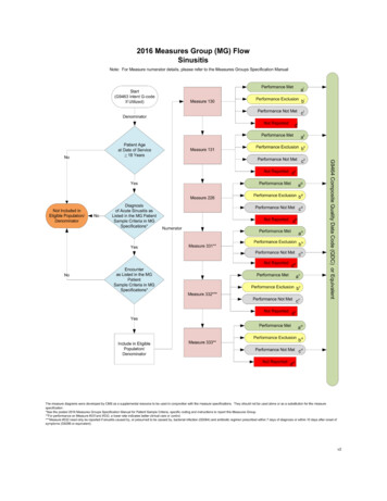
Mechanical Engineering TechnologyPower Plant Engineering and Economy MET 401DefinitionsSubcooled or compressedSaturated liquidWet (mixture)Saturated vaporSuperheatedQuality (x)WaterDTSubcooled water (A)Saturated liquid (B) (x 0)Evaporation of saturated liquid (B-C) (x 0 1)Wet steam (F) (x )Dry Saturated steam (C) ) (x 1)Superheated steam (D)x BFCAvapour masstotal masss1.5- The enthalpy-entropy diagramThe Mollier diagram, shown in Figure 1.1, is a chart on which enthalpy (h) versusentropy (s) is plotted. It is sometimes known as the h-s diagram and has anentirely different shape from the T-s diagrams. The chart contains a series of constanttemperature lines, a series of constant pressure lines, a series of constant quality lines,and a series of constant superheat lines. The Mollier diagram is used only when qualityis greater than 50% and for superheated steam.Figure 1.1 Dr. Rahim K. Jassim9
Mechanical Engineering TechnologyPower Plant Engineering and Economy MET 401Example 1.1Heat is transferred to a dry saturated steam at 193 oC until it’s superheated by 167 oC,while the pressure remains constant, determine h.Example 1.2Steam at 300 oC and 0.5 MPa is expanded in a reversible adiabatic process (isentropic)to 0.01 MPa, determine h and x. Dr. Rahim K. Jassim10
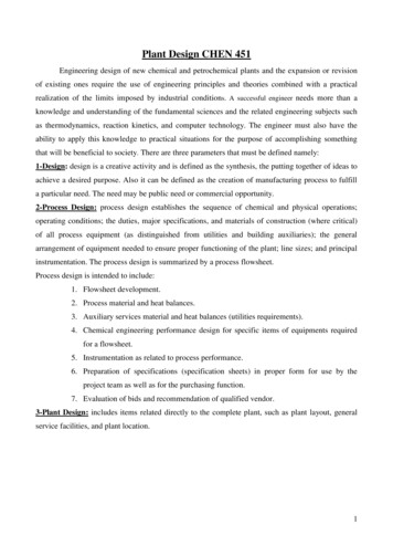
Mechanical Engineering TechnologyPower Plant Engineering and Economy MET 4011.6- Thermodynamics reviewWe have already discussed the first law of thermodynamics: control volume in appliedthermodynamics and heat transfer subject.1.6.1- Conservation of mass and the control volumeThe conservation of mass is one of the most fundamental principles in nature. We are allfamiliar with this principles, and it is not difficul to understand. For closed systems, theconservation of mass principles is implicitly used by requiring that the mass of thesystem remains constant during a process. For control volumes (see Figure 1.2),however, mass can cross the boundaries, and so we must keep track of the amount ofthe mass entering and leaving the control volume (see Figure 1.2). The conservation ofmass principle for the control volume (CV) undergoing a process can be expressed as m CV m i m eThe average rate of change of mass within the control volumedmCV m& i m& edttotaltotal net change in mass within mass entering mass leaving control volume control volume control volume (1.1)me2 kg m CVFigure 1.2mi 3 kg5 kgEquation (1.1) for the conservation of mass is commonly termed the Continuity Equation.While this form of the equation is sufficient for the majority of applications inthermodynamics, it is frequently rewitten in terms of local fluid properties in the study offluid dynamics and heat transfer.Let us consider one further aspect of mass flow across a control volume. For simplicity,we assume that a fluid is flowing uniformaly inside a pipe or duct, as shown in Figure1.3. Dr. Rahim K. Jassim11
Mechanical Engineering TechnologyPower Plant Engineering and Economy MET 401VAFlowdsFigure (1.3)We wish to examine the flow in terms of the amount of mass crossing the surface Aduring the time interval δt . As seen from the figure above, the fluid moves a distanceds during this time, and therefore the volume of fluid crossing surface A is A ds.Consequently, the mass crossing surface A is given byδm A dsvIf both sides of the above expression is devided by δt and take the limit δt 0 , theresult is& mAVv(1.2)Where V is the fluid velocity m/sA cross sectional area m21.6.2-The First law of Thermodynamics for a Control VolumeThe first law of thermodynaocs for a control mass, which consists of a fixed quantity ofmass is expressed as1Q2 E 2 E1 1W2This expression can be written as a rate equation dE V 2 V 2 Q& c.v. m& i hi i g Z i 10 3 c.v m& e he e g Z e 10 3 W& c.v. (1.3) dt 2 2 The first application of the first law of thermodynamics for the control volume will be todevelop a suitable analytical model for SSSF operation of devices such as turbines,compressors, nozzles, boilers, heat excangers, etc.SSSF assumptionsdmc.v. 0dtanddE c.v. 0dtThen, equations (1.1 and 1.3) can be written, m& m&i Dr. Rahim K. Jassime12
Mechanical Engineering TechnologyPower Plant Engineering and Economy MET 401 V 2 V 2 Q& c.v . m& i hi i g Z i 10 3 m& e he e g Z e 10 3 W& c.v . 2 2 In many applications of SSSF model have only one flow stream entering and one leavingthe control volume. Thenm& i m& e m&(1.4) Vi 2 Ve2 3& &&Qc.v . m hi g Z i 10 m he g Z e 10 3 W& c.v. 2 2 (1.5)Rearranging this equation, we have V 2 V 2 q hi i g Z i 10 3 he e g Z e 10 3 w 2 2 (1.6)where, by definition,q Q& c.vm&and Dr. Rahim K. Jassimw W& c.vm&(1.7)13
Mechanical Engineering TechnologyPower Plant Engineering and Economy MET 4011.6.3- Power CyclesTwo important area of application for SSSF or cylinder/piston boundary work processesof thermodynamics are power generation and refrigeration systems. Both systemsare accomplished by operating on a thermodynamic cycles. These cycles are generallydivided into two categories: power cycles and refrigeration cycles.The systems used to produce a net power output are often called engines (i.e. steampower plant, internal combustion engine and gas turbine) and the thermodynamic cyclesthey operate on are called power cycles. Whereas, the systems used to producerefrigeration are called refrigerators, air conditioners, or heat pumps, and thethermodynamic cycles they operate on are called refrigeration cycles.Thermodynamic cycles can be categories to: Closed cycles and open cycles. In closedcycles, the working fluid is returned to the initial state at the end of the cycle and isrecirculated (i.e. steam power plant, refrigerators) . In open cycle, the working fluid isrenewed at the end of each cycle (i.e. internal combustion engine, gas turbine).In this course, the focus will be only on power cyclesIn gas power cycle, the working fluid remains a gas throughout the entire cycle. Internalcombustion engine, gas turbines are familiar examples of devices that operate on gascycles. Analysis of these cycles are rather complex. To simplify the analysis to amanageable level, we utilize the following assumptions, commonly known as the air –standard assumptions.1. The working fluid is air that continuously circulates in a closed loop and alwaysbehaves as an ideal gas.Some important relationsdu C vo dT(1.8 a)dh C po dT(1.8 b)P2 V1 P1 V2 T2 P2 T1 P1 kwhere k k 1k V 1 V2 C poC vo(1.9 a)k 1(1.9 b)Also, the specific heat of air is constant and is evaluated at 25oC2. All the processes that make up the cycle are internally reversible3. The combustion process is replaced by a heat addition process from external anexternal source (Figure 1.4).4. The exhaust process is replaced by a heat rejection process that restores theworking fluid to its initial state. Dr. Rahim K. Jassim14
Mechanical Engineering TechnologyPower Plant Engineering and Economy MET 401Figure (1.4)1.6.4 - Reciprocating enginesThe basic components of a reciprocating engine are shown in Figure 1.5. The pistonreciprocates in the cylinder between two fixed positions called the top dead center(TDC)—the position of the piston when it forms the smallest volume in the cylinder—andthe bottom dead center (BDC)—the position of the piston when it forms the largestvolume in the cylinder. The distance between the TDC and the BDC is the largestdistance that the piston can travel in one direction, and it is called the stroke of theengine. The diameter of the piston is called the bore. The air or air-fuel mixture is drawninto the cylinder through the intake valve, and the combustion products are expelledfrom the cylinder through the exhaust valve.The minimum volume formed in the cylinder when the piston is at TDC is called theclearance volume (Figure 1.6). The volume displaced by the piston as it movesbetween TDC and BDC is called the displacement volume. The ratio of the maximumvolume formed in the cylinder to the minimum clearance volume is called thecompression ratio ( r ) of the engine:r Vmax V BDC Vmin VTDC Dr. Rahim K. Jassim(1.10)15
Mechanical Engineering TechnologyPower Plant Engineering and Economy MET 401Figure (1.5)Figure (1.6)Notice that the compression ratio is a volume ratio and should not be confused with thepressure ratio.Another term frequently used in conjunction with reciprocating engines is the MeanEffective Pressure (MEP). It is a fictitious pressure which, if it acted on the pistonduring the entire power stroke, would produce the same amount of net work as thatproduced during the actual cycle (Figure 1.7). That is,Wnet., MEP X piston area X stroke MEP X displacement volumeMEP Wnetwnet Vmax Vmin v max v min(1.11)The mean effective pressure can be used as a parameter to compare the performancesof reciprocating engines of equal size. The engine that has a larger value of MEP willdeliver more net work per cycle and thus will perform better.Figure (1.7) Dr. Rahim K. Jassim16
Mechanical Engineering TechnologyPower Plant Engineering and Economy MET 4011.6.4.1- Otto CycleThe air standard Otto cycle is an ideal cycle approximates a spark-ignition internalcombustion engine (IC). This cycle is shown on P-v and T-s diagrams of Figure (1.8).Process 1-2 is an isentropic compression (s c) of the air as the piston moves from BDCto TDC.Process 2-3 heat is added at constant volume while the piston is momentarily at rest atthe TDC point. (This process corresponds to the ignition of the fuel air mixture by thespark and subsequent burning in the engine).Process 3-4 is an isentropic expansion (s c), andProcess 4-1 is the heat rejection of heat from the air while the piston is at BDC (v c).The thermal efficiency of this cycle is found as follows,ηth ,Otto T T1 4 1 Tm C vo (T4 T1 )Q 1 L 1 1 1QHm C vo (T3 T2 ) T T2 3 1 T2 WnetQH(1.12)Processes 1-2 and 3-4 are isentropic, and v2 v3 and v4 v1. ThusT2 V1 T1 V2 k 1 V 4 V3 k 1 T3T4(1.13)Therefore,T3 T4 T2 T1(1.14)andηth ,Otto 1 T111 k 1 (r ) 1 k 1T2(r )(1.15)wherer V1 V4 V2 V3(1.16)Example 1.3An ideal Otto cycle has a compression ratio of 8. At the beginning of the compressionprocess, the air is at 100 kPa and 17 oC, and 1800 kJ/kg of heat is transferred to airduring the constant-volume heat addition process. Determinea- the maximum temperature and pressure that occur during the cycle.b- the net work outputc- the thermal efficiency, andd- the mean effective pressure for the cycle Dr. Rahim K. Jassim17
Mechanical Engineering TechnologyPower Plant Engineering and Economy MET 401Solution. Dr. Rahim K. Jassim18
Mechanical Engineering TechnologyPower Plant Engineering and Economy MET 401(a)(b)Figure (1.8)1.6.4.2- The Diesel CycleThe air-standard Diesel cycle is shown in Figure 1.9. This is the ideal cycle for the dieselengine, which is also called the compression-ignition engine.The Diesel cycle is the ideal cycle for Cl reciprocating engines. The Cl engine, firstproposed by Rudolph Diesel in the 1890s, is very similar to the S
1. Basic thermodynamics of power cycles and combustion processes 2. Conduction, convection and radiation heat transfer CO-REQUISITE: None COMPUTER USAGE: Use of computer programs in power plant calculations TEXT AND MATERIALS: Textbook: 1. Power Plant Engineering. by Nag, P.K