Transcription
DESGNDesigning for CiscoInternetworkSolutionsVersion 2.1Lab GuideText Part Number: 97-2918-01
DISCLAIMER WARRANTY: THIS CONTENT IS BEING PROVIDED “AS IS.” CISCO MAKES AND YOU RECEIVE NO WARRANTIES INCONNECTION WITH THE CONTENT PROVIDED HEREUNDER, EXPRESS, IMPLIED, STATUTORY OR IN ANY OTHER PROVISION OFTHIS CONTENT OR COMMUNICATION BETWEEN CISCO AND YOU. CISCO SPECIFICALLY DISCLAIMS ALL IMPLIEDWARRANTIES, INCLUDING WARRANTIES OF MERCHANTABILITY, NON-INFRINGEMENT AND FITNESS FOR A PARTICULARPURPOSE, OR ARISING FROM A COURSE OF DEALING, USAGE OR TRADE PRACTICE. This learning product may contain early releasecontent, and while Cisco believes it to be accurate, it falls subject to the disclaimer above.Lab Guide 2010 Cisco and/or its affiliates. All rights reserved.
Table of ContentsLab GuideOverviewOutlineCase Study GuidelinesCase Study 1-1: ACMC Hospital Network Upgrade InformationActivity ObjectiveVisual ObjectiveRequired ResourcesACMC Hospital Network Upgrade ScenarioACMC Hospital Network Upgrade TasksCase Study 2-1: ACMC Hospital Network Structure and ModularityActivity ObjectiveVisual ObjectiveRequired ResourcesACMC Hospital Network Structure and Modularity TasksCase Study 3-1: ACMC Hospital Network Campus DesignActivity ObjectiveVisual ObjectiveRequired ResourcesACMC Hospital Case Study ScenarioACMC Hospital Network Campus Design TasksCase Study 4-1: ACMC Hospital Network WAN DesignActivity ObjectiveVisual ObjectiveRequired ResourcesACMC Hospital Case Study ScenarioACMC Hospital Network WAN Design TasksCase Study 5-1: ACMC Hospital Network IP Addressing and Routing Protocol DesignActivity ObjectiveVisual ObjectiveRequired ResourcesACMC Hospital Case Study ScenarioACMC Hospital Network IP Addressing and Routing Protocol Design TasksCase Study 6-1: ACMC Hospital Network Security DesignActivity ObjectiveVisual ObjectiveRequired ResourcesACMC Hospital Case Study ScenarioACMC Hospital Network Security Design TasksCase Study 7-1: ACMC Hospital Network Voice Transport ConsiderationsActivity ObjectiveVisual ObjectiveRequired ResourcesACMC Hospital Case Study ScenarioACMC Hospital Network Voice Transport Consideration TasksCase Study 8-1: ACMC Hospital Network Unified Wireless Networking ConsiderationsActivity ObjectiveVisual ObjectiveRequired ResourcesACMC Hospital Case Study ScenarioACMC Hospital Network Unified Wireless Networking TasksCase Study 8-2: Connecting More Hospitals to the ACMC Hospital NetworkActivity ObjectiveVisual ObjectiveRequired ResourcesACMC Hospital Case Study ScenarioConnecting More Hospitals to the ACMC Hospital Network TasksAnswer KeyCase Study 1-1 Answer Key: ACMC Hospital Network Upgrade 141414242424848
Case Study 2-1 Answer Key: ACMC Hospital Network Structure and ModularityNew RequirementsCase Study 3-1 Answer Key: ACMC Hospital Network Campus DesignCase Study 4-1 Answer Key: ACMC Hospital Network WAN DesignCase Study 5-1 Answer Key: ACMC Hospital Network IP Addressing and Routing ProtocolDesignCase Study 6-1 Answer Key: ACMC Hospital Network Security DesignCase Study 7-1 Answer Key: ACMC Hospital Network Voice Transport ConsiderationsCase Study 8-1 Answer Key: ACMC Hospital Network Unified Wireless NetworkingConsiderationsCase Study 8-2 Answer Key: Connecting More Hospitals to the ACMC Hospital NetworkCourse WorksheetsiiDesigning for Cisco Internetwork Solutions (DESGN) v2.151555762667075778185 2010 Cisco Systems, Inc.
DESGNLab GuideOverviewThis guide presents the instructions and other information concerning the lab activities for thiscourse. You can find the solutions in the lab activity Answer Key.OutlineThis guide includes these activities: Case Study 1-1: ACMC Hospital Network Upgrade Information Case Study 2-1: ACMC Hospital Network Structure and Modularity Case Study 3-1: ACMC Hospital Network Campus Design Case Study 4-1: ACMC Hospital Network WAN Design Case Study 5-1: ACMC Hospital Network IP Addressing and Routing Protocol Design. Case Study 6-1: ACMC Hospital Network Security Design. Case Study 7-1: ACMC Hospital Network Voice Transport Considerations. Case Study 8-1: ACMC Hospital Network Wireless Networking Considerations. Case Study 8-2: Connecting More Hospitals to the ACMC Hospital Network. Answer Key Course Worksheets
Case Study GuidelinesFollow these guidelines for each case study:2 Use the scenarios, information, and parameters that are provided with each task of the casestudy. If there are ambiguities, make reasonable assumptions and proceed. For all the tasks,use the initial customer scenario and build on the solutions that you have developed so far. Use any documentation, books, white papers, and so on. Use any design strategies that you feel are appropriate. In each task of the case study, you act as a network design consultant. Make creativeproposals to help the enterprise accomplish its goals. When your ideas differ from theprovided solutions, justify your ideas. To maximize class interaction and make good use of time, the instructor will ask you towork in groups. Each group should reach consensus on the answers to the questions. If yourgroup is assigned to present a design, pick one member to present. Provide that person withthe notes and drawings that are needed to successfully present the design to the class. Aftera brief presentation of the design, presenters will be expected to answer questions andexplain the group design decisions and reasoning. To give the student the opportunity to design a modern network, the initial topology wasintentional designed with older technology.Designing for Cisco Internetwork Solutions (DESGN) v2.1 2010 Cisco Systems, Inc.
Case Study 1-1: ACMC Hospital Network UpgradeInformationThis case study enables you to practice the skills and knowledge that you learned in themodule.Activity ObjectiveIn this activity, you will create a high-level design for updating the ACMC Hospital network.After completing this activity, you will be able to meet these objectives: Document the requirements of the organization Document the existing network Identify and request missing information Outline the major design tasks for the networkVisual ObjectiveThere is no visual objective for this case study.Required ResourcesThe following are the resources and equipment that are required to complete this activity: Case study guidelines, presented in the Lab Guide Overview ACMC Hospital network upgrade scenario A workgroup of two to four learners Blank sheets of paper and a pencilACMC Hospital Network Upgrade ScenarioThis case study analyzes the network infrastructure of Acme County Medical Center (ACMC)Hospital, a fictitious, small, county hospital. Hospital management gave you a short descriptionof the current situation and its plans. It is your job, as an independent network designer, toidentify all of the organizational requirements and data that will allow you to provide aneffective solution.Organizational FactsACMC is a regional hospital with approximately 500 staff members supporting up to 1000patients. The hospital is interested in updating its main facility from Brand X equipment in itsLayer 2 campus. You are meeting with hospital management to define its requirements.There are 15 buildings on the hospital campus, plus five small remote clinics. There areseven floors in each of the two main hospital buildings, with four wiring closets per floor inthe main buildings. The auxiliary building, the Children’s Place, is connected by fiber to themain buildings. (The three main building switches are connected by fiber into a ring.) TheChildren’s Place has three floors, with three wiring closets per floor. The other 12 campusbuildings are smaller office and support facilities, with 10 to 40 people per building that arelocated on one or two floors. 2010 Cisco Systems, Inc.Lab Guide3
The network architect is new to the hospital. The hospital management is aggressively expandingclinic and alternative emergency room presence within Acme County. Due to general populationgrowth, there are also plans to enlarge the main campus. The hospital is doing fairly wellfinancially. It wishes to selectively deploy innovative technology for better patient care andhigh productivity. Network downtime or slowness has been affecting patient care. Networkmanageability is important because ACMC has a tradition of basing operations on small supportstaffs with high productivity. The timeframe for the ACMC upgrade is 6 to 12 months.Current SituationThe current network uses inexpensive switches that were purchased over time from severalvendors. They comply with various standards, depending on when they were purchased. Theyare not SNMP-manageable switches, although a small amount of information is available fromeach switch via the web or command-line interface (CLI).There is a main switch within each of the three main buildings. One floor switch from each floorconnects to the main switch. The other switches connect either directly to the floor switch or via adaisy chain of switches, depending on which was most convenient at the time of installation.The small outlying buildings have one or two 24-port switches. One of these switches connectsback to one of the main building switches via fiber. If there is a second switch, it connects viathe first switch.Currently, the staff VLAN spans the entire campus. There is no Layer 3 switching. The addressspace is 172.16.0.0 /16. Addresses were coded sequentially into PCs as they were deployed.Although the staff would like to deploy DHCP, it has not yet done so.The organization is currently running standard office applications, plus some specializedmedical programs running over IP. Radiology, Oncology, and other departments performmedical imaging. As these departments acquire new tools, they are adding real-time motion tothe highly detailed medical images. This process requires large amounts of bandwidth. All ofthe new servers are capable of using Gigabit or GEC connectivity.Many servers are currently located in various closets. Many of the servers lack UPS or properenvironmental controls. The staff rolls a tape backup cart to each server closet to back up eachserver. There are about 40 centrally located servers in one raised floor server room and 30 otherservers that are distributed around the campus near their users. The server room, the cafeteria,and other non-networked areas comprise the first floor of Main Building 1.Hospital Support Services has been experimenting with workstations on wheels (WoWs). It hasproved inefficient to move these WoWs and plug them into an Ethernet jack.The WAN uses DS0 (56 kb/s) links to three of the remote clinics and PC dialup connectivityto the other two. The one router uses static routing that was configured by a previous networkdesigner.The staff members have frequently complained about slow response times. There appears to besevere congestion of the LAN, especially during peak hours. The staff provided you with acopy of the recent network diagram.4Designing for Cisco Internetwork Solutions (DESGN) v2.1 2010 Cisco Systems, Inc.
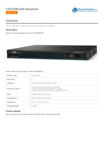
Case Study 1-1: ACMC Network Core 2010 Cisco Systems, Inc. All rights reserved.DESGN v2.1—LG-2You believe that the current situation does not provide for future growth, high reliability, andease of management.Plans and RequirementsThe introduction of new applications will result in an additional load on the links to remoteclinics. The expected tighter integration and growth of remote offices will even further increasethe traffic load on the WAN links. The hospital would like to upgrade the WAN infrastructure toprovide sufficient bandwidth between the remote clinics and headquarters. At the same time, thehospital would like to find a solution for better convergence during network failures.Management is aware of the drawbacks of the current IP addressing scheme and is seeking abetter solution.ACMC Hospital Network Upgrade TasksComplete these steps:Step 1Read the ACMC Hospital Network Upgrade scenario information completely beforebeginning the activity. Allow 10 minutes for reading.Step 2Discuss the scenario with your group. Allow 20 minutes for a discussion.Step 3Document the ACMC Hospital requirements in the “Requirements” table. 2010 Cisco Systems, Inc.Lab Guide5
RequirementsRequirementStep 46CommentIn the “Missing Items” table, document any information that you think is missingfrom the scenario and that you consider necessary for the design. Teams askquestions of “the customer” (the instructor) to obtain the missing details. Allow 10minutes for this step.Designing for Cisco Internetwork Solutions (DESGN) v2.1 2010 Cisco Systems, Inc.
Missing ItemsMissing ItemStep 5Note 2010 Cisco Systems, Inc.Customer Response (Provided by Instructor)Outline the major design areas that you need to address in designing the solution forthe given customer scenario. List the tasks, and provide a brief comment for eachtask in the “Major Design Tasks” table.The Cisco Network Architectures for the Enterprise is covered in “Case Study 2-1: ACMCHospital Network Structure and Modularity.” However, you should already be aware of theterms such as campus, WAN, and server farm, and you may discuss broad areas of designusing those terms.Lab Guide7
Major Design TasksDesign TasksStep 6Present your design to the class. Be prepared to justify your design choices.Activity VerificationYou have completed this activity when the instructor has verified your case study solution, andyou have justified any major deviations from the solution that is supplied by the instructor.8Designing for Cisco Internetwork Solutions (DESGN) v2.1 2010 Cisco Systems, Inc.
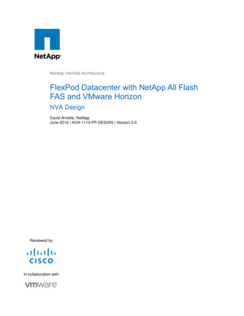
Case Study 2-1: ACMC Hospital NetworkStructure and ModularityThis case study enables you to practice the skills and knowledge that you learned in the module.Activity ObjectiveIn this activity, you will apply the Cisco Network Architectures for the Enterprise to the ACMCHospital network requirements. You will develop a high-level sketch of the planned networkhierarchy. You will also present your diagram and high-level design features to the class.After completing this activity, you will be able to meet these objectives: Diagram the planned network hierarchy Discuss and document some details of the design of each of the modules in the planneddesign Discuss and document the use of infrastructure services within your design at a high levelVisual ObjectiveThe visual objective is to diagram the planned network hierarchy.Case Study 2-1: Modular Diagram 2010 Cisco Systems, Inc. All rights reserved.DESGN v2.1—LG-3Required ResourcesThe following are the resources and equipment that are required to complete this activity: Case study guidelines, presented in the Lab Guide Overview ACMC Hospital case study scenario A workgroup of two to four learners Blank sheets of paper and a pencil 2010 Cisco Systems, Inc.Lab Guide9
ACMC Hospital Network Structure and Modularity TasksComplete these steps.Step 1Consider each of the Cisco Network Architectures for the Enterprise modules andcomponents. At a high level, determine how and where they belong in your designfor the future ACMC Hospital network. Cisco Enterprise Campus Architecture: Campus infrastructure module (campuscore layer, building distribution layer, and building access layer) and server farmmodule Cisco Enterprise WAN and MAN Architecture: E-commerce module, Internetconnectivity module, remote access and VPN module, and WAN and MAN andsite-to-site VPN module Cisco Enterprise Branch Architecture Cisco Enterprise Data Center Architecture wqMark up the existing diagram with your conclusions. Identify each of the CiscoNetwork Architectures for the Enterprise modules. Be as specific as possible. Youwill add detail to individual modules later.10Step 2On a piece of paper, list three to five key considerations or functions for eachmodule. If the module is not being used, state that.Step 3You provided a written document to the customer, describing the customerrequirements you heard during your initial ACMC discussions. Since then,discussions with ACMC have identified these additional requirements:Designing for Cisco Internetwork Solutions (DESGN) v2.1 2010 Cisco Systems, Inc.
The staff needs Internet access for purchasing supplies and reviewing researchdocuments and new medical products. ACMC has a web server for patient communications and community relationsthat is called the “Text a Nurse” service. This service allows a patient to send atext message to the hospital for medical advice.Step 4How does this new information change the design? Add the new information to yourhigh-level design, and update your list of modules and considerations.Step 5Which of these infrastructure or network services are immediately applicable to yourdesign, based on the ACMC business objectives and technical requirements from“Case Study 1-1: ACMC Hospital Network Upgrade Information”? Are therespecific locations or modules where some of these services are particularly relevant?Identify these locations or modules in your diagram. Be prepared to describe theseservices during your presentation. Security services Voice services Network management High availability QoSStep 6Should your design incorporate redundancy? Does it do so? Make sure that yourdiagram shows appropriate redundancy or indicates the modules or locations whereredundancy is appropriate.Step 7Present your design to the class. Be prepared to justify your design choices.Activity VerificationYou have completed this activity when you have created a high-level design diagram and havedocumented the relevant Cisco Network Architectures for the Enterprise modules, includingthree to five considerations for each relevant module.If time permits, the questions and comments in response to your presentation will providevaluable feedback for your design. This feedback offers you an opportunity to see what aspectsof this design you might have overlooked. 2010 Cisco Systems, Inc.Lab Guide11
Case Study 3-1: ACMC Hospital Network CampusDesignThis case study enables you to practice the skills and knowledge that you learned in the module.Activity ObjectiveIn this activity, you will create a high-level design for the Cisco Enterprise CampusArchitecture and Cisco Data Center Architecture of the ACMC Hospital network. Aftercompleting this activity, you will be able to meet these objectives: Describe the proposed campus design Document and diagram the proposed campus designVisual ObjectiveThe visual objective is to diagram the proposed campus design solution.Required ResourcesThe following are the resources and equipment that are required to complete this activity:12 Case study guidelines, presented in the Lab Guide Overview ACMC Hospital case study scenario A workgroup of two to four learners Blank sheets of paper and a pencilDesigning for Cisco Internetwork Solutions (DESGN) v2.1 2010 Cisco Systems, Inc.
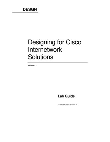
ACMC Hospital Case Study ScenarioIn this section, you will fill in the details of the design, including port counts and cabling. Thiscase study focuses on the enterprise campus and server farm. This diagram shows the campusdevice counts.Case Study 3-1: Campus Device Counts 2010 Cisco Systems, Inc. All rights reserved.DESGN v2.1—LG-6Port Count DetailsThe hospital has 500 staff members and 1000 patients. Specifically, buildings A through Dhave 10 people each, buildings E through J have 20 people each, and buildings K through Lhave 40 people each. Assume that each building needs as many spare ports as there are people.Each floor of the Children’s Place has 60 people on it. Each floor of the main buildings hasabout 75 people on it, except the first floor of Main Building 1, which has only the server farmwith 40 servers. Assume that each floor needs as many spare ports as there are people. (Eachpatient room or staff position has two jacks, and spare server ports should be provided to allowfor migration of all servers to the server farm.)Cabling DetailsAssume that the hospital has structured cabling with plenty of multimode fiber (MMF) in therisers and plenty of fiber between buildings along all paths that are shown in the diagrams in“Case Study 1-1: ACMC Hospital Network Upgrade” and “Case Study 2-1: DefiningModularity.”Note 2010 Cisco Systems, Inc.If there is not enough fiber, either the hospital will have to install the fiber, or you will have toadjust your design to the existing cabling. However, it is best to work out an ideal designbefore making any adjustments.Lab Guide13
ACMC Hospital Network Campus Design TasksComplete these steps:Step 1Determine the location, quantity, and size of the core switch or switches and whatconnections there should be within the core.Step 2Determine the location of distribution layer switches or whether a collapsed core ora core/distribution approach makes more sense. If you use a design with distributionlayer switches, determine their location and size, how they connect to the core, theuse of VLANs versus Layer 3 switching, and so on.Step 3Determine the location and size of access layer switches. Complete the “Port Countsby Location” table.Port Counts by LocationLocationCountsMain Building 1 (Per Floor)Counts withSparesCommentssix floorsMain Building Server FarmMain Building 2 (Per Floor)seven floorsChildren’s Place (Per Floor)three floorsBuildings A–DBuildings E–JBuildings K–L14Step 4Determine how the access layer switches connect to the distribution layer switches(or to the combined core/distribution switch or switches). Include such informationas speeds, cabling type, and location.Step 5Verify that you have the correct port counts for all the switches in your design.Step 6Determine how you will manage the server farm. Do you propose connecting theservers to the core switch or switches? To server aggregation switches? Other? Ifyou use server access or distribution switches, determine how they all connect toeach other and to the core.Step 7How do the 12 additional buildings (buildings A through L) affect your design? Besure to determine what size switches to use in each building, and how they connectback to the distribution or core layers.Step 8Other than port counts, speeds, and feeds, is there any other information that wouldbenefit your design?Designing for Cisco Internetwork Solutions (DESGN) v2.1 2010 Cisco Systems, Inc.
Determine appropriate Cisco switch models for each part of your campus design.Use these links to assist you:Step 9 The Cisco switch main page index.html The Cisco switch comparison page products category buyers guide.html The Cisco Catalyst Switch Solution Finder witches/products promotion0900aecd8050364f.htmlIf time permits and you have access to a computer and the Internet, perform Steps 10 and 11.(Optional) Use the Cisco Dynamic Configuration Tool to configure one or more ofthe switches in your design.Step 10NoteThis process is easier and faster if you use the same two or three switch models repeatedlyin your design, possibly with different numbers of blades in them. Also, there are not manyoptions for the smaller switches in the configuration tool. Start ering ordering help dynamic configuration tool launch.html. This link requires a valid Cisco.comusername and password. Click to launch the tool. After you select the product family and the startingbundle or chassis, this screen appears.Cisco Ordering Dynamic ConfigurationTool 2010 Cisco Systems, Inc. All rights reserved. 2010 Cisco Systems, Inc.DESGN v2.1—LG-7Lab Guide15
(Optional) Develop a Bill of Materials (BOM) that lists switch models, numbers,prices, and total price. If you have access to a PC with spreadsheet software, youmay use a spreadsheet to develop the BOM. If not, work on paper. The following isa sample BOM.Step 11Sample Bill of Materials9/8/2010 11:05Version 1Part NumberDescriptionUnit PriceQty Extended PriceWS-C2960S-24TS-LCatalyst 2960 24 10/100/1000 2T/SFPLAN Base Image 150070Generic SFP 400140 56,000Catalyst 3750 48 10/100/1000T 4 SFP IPS Image 10,00034Generic SFP 400136 54,400WS-C4507RCatalyst 4500 Chassis (7-Slot), Fan, NoPower Supply, Redundant SupervisorCapable 70002 14,000PWR-C45-1400ACCatalyst 4500 1400W AC Power Supply(Data Only) 10002 2000WS-X4516Catalyst 4500 Supervisor V (2 GigabitEthernet),Console (RJ-45) 11,0002 22,000S4KL3E-12220EWACisco IOS Enhanced Layer 3 Catalyst 4500 10,000Supervisor 4/5 (OSPF, EIGRP, IS-IS)2 20,000WS-X4306-GBCatalyst 4500 Gigabit Ethernet Module, 6Ports (GBIC)6 12,600WS-C3750G-48TS-E 2100 105,000 340,000Total list price 626,000Customer discount15%Discounted price 532,100Because looking up component prices and building a BOM can be time-consuming, use the“Sample Price List” table for abbreviated and simplified price list information. The prices thatare shown are not actual equipment prices and are loosely derived from Cisco list prices at thetime this course was written.16Designing for Cisco Internetwork Solutions (DESGN) v2.1 2010 Cisco Systems, Inc.
Sample Price ListCategoryPart NumberDescriptionFictional PriceGeneric SFP 400Generic GBIC 400Generic LR Xenpack 4,000Port Transceiver ModulesCisco Catalyst 2960 Series Workgroup SwitchesWS-C2960-24LT-LCatalyst 2960 24 10/100 (8 PoE) 2 1000BT LAN Base Image 2,500WS-C2960-24PC-LCatalyst 2960 24 10/100 PoE 2 T/SFP LAN Base Image 1,300WS-C2960G-48TC-LCatalyst 2960 48 10/100/1000, 4 T/SFP LAN Base Image 4,500WS-C2960-48TT-LCatalyst 2960 48 10/100 Ports 2 1000BT LAN Base Image 2,500WS-C2960G-24TC-LCatalyst 2960 24 10/100/1000, 4T/SFP LAN Base Image 3,300WS-C2960G-48TC-LCatalyst 2960 48 10/100/1000, 4T/SFP LAN Base Image 6,000WS-C3560G-48TS-SCatalyst 3560 48 10/100/1000T 4 SFP Standard Image 8,000WS-C3560G-24TS-SCatalyst 3560 24 10/100/1000T 4 SFP Standard Image 4,800WS-C3560-48TS-SCatalyst 3560 48 10/100 4 SFP Standard Image 5,000WS-C3560-24TS-SCatalyst 3560 24 10/100 2 SFP Standard Image 3,000Cisco Catalyst 3560 SeriesCisco IOS Upgrades for the Catalyst 3560 (EMI Layer 3 image)CD-3560-EMI Enhanced Multilayer Image upgrade for 3560 10/100 modelsCD-3560G-EMI Enhanced Multilayer Image upgrade for 3560 Gigabit Ethernet 4,000models 2010 Cisco Systems, Inc. 2,000Lab Guide17
CategoryPart NumberFictionalPriceDescriptionCisco Catalyst 3750 Series 10/100/1000, Gigabit Ethernet, 10GE Workgroup SwitchWS-C3750G-24T-SCatalyst 3750 24 10/100/1000T Standard Multilayer Image 6,000WS-C3750G-24TS-S1UCatalyst 3750 24 10/100/1000 4 SFP Std Multilayer 1RU 7,000WS-C3750G-48TS-SCatalyst 3750 48 10/100/1000T 4 SFP Standard Multilayer 14,000WS-C3750E-24PD-SCatalyst 3750E 24 10/100/1000 PoE 2*10GE(X2),750W,IPBs/w 12,000WS-C3750G-12S-SCatalyst 3750 12 SFP Standard Multilayer Image 8,000Cisco Catalyst 3750 Series 10/100 Workgroup SwitchesWS-C3750-24TS-SCatalyst 3750 24 10/100 2 SFP Standard Multilayer Image 4,000WS-C3750-48TS-SCatalyst 3750 48 10/100 4 SFP Standard Multilayer Image 7,000CD-3750-EMI Enhanced Multilayer Image upgrade for 3750 Fast Ethernetmodels 2,000CD-3750G-EMI Enhanced Multilayer Image upgrade for 24-port 3750 GigabitEthernet models 4,000CD-3750G-48EMI Enhanced Multilayer Image upgrade for 48-port 3750 GigabitEthernet models 8,0003750-AISK9-LIC-B Advanced IP Services upgrade for 3750 Fast Ethernet models 5,000running SMI3750G-AISK9-LIC-B Advanced IP Services upgrade for 3750 Gigabit Ethernetmodels running SMI 7,0003750G48-AISK9LC-B Advanced IP Services upgrade for 3750G-48 running SMI 11,000WS-C4948-SCatalyst 4948, IPB software, 48-Port 10/100/1000 4 SFP, 1AC power supply 10,500WS-C4948-ECatalyst 4948, ES software, 48-Port 10/100/1000 4 SFP, 1AC power supply 14,500WS-C4948-10GE-SCatalyst 4948, IPB software, 48*10/100/1000 2*10GE(X2), 1AC power supply 17,500WS-C4948-10GE-ECatalyst 4948, ES Image, 48*10/100/1000 2*10GE(X2), 1-ACpower supply 21,500Cisco IOS Upgrades for the Catalyst 3750Cisco Catalyst 4948 SwitchCisco Catalyst 4948 2225SG18Cisco Catalyst 4948 IOS Stand Layer 3 3DES (RIP, St.Routes, IPX, AT) 0Cisco Catalyst 4948 IOS Enhanced Layer 3 3DES (OSPF,EIGRP, IS-IS, BGP) 4,000Cisco Catalyst 4900 IOS Enterprise Services SSH 4,000Designing for Cisco Internetwork Solutions (DESGN) v2.1 2010 Cisco Systems, Inc.
CategoryPart NumberFictionalPriceDescriptionCisco Catalyst 4500 ChassisWS-C4510RCatalyst 4500 Chassis (10-Slot), fan, no power supply,Redundant Supervisor Capable 12,500WS-C4507RCatalyst 4500 Chassis (7-Slot), fan, no power supply,Redundant Supervisor Capable 10,000WS-C4506Catalyst 4500 Chassis (6-Slot),fan, no power supply 5,000WS-C4503-ECat4500 Cat4500 E-Series 3-Slot Chassis, fan, no psE-Series 3-Slot Chassis,fan, no ps 1,000WS-C4506-S2 96Catalyst 4506 Bundle, 1x 1000AC, 1x S2 , 2x WS-X4148-RJ 16,800WS-C4503-S2 48Catalyst 4503 Bundle, 1x 1000AC, 1x S2 , 1x WS-X4148-RJ 10,000Cisco Catalyst 4500 Non-PoE Power SuppliesPWR-C45-1400ACCatalyst 4500 1400W AC Power Supply (Data Only) 1,500PWR-C45-1000ACCatalyst 4500 1000W AC Power Supply (Data Only) 1,000WS-X4516-10GECatalyst 4500 Supervisor V-10GE, 2x10GE (X2) and 4x1GE(SFP) 20,000WS-X4516-10GE/2Catalyst 45xxR Supervisor V-10GE, 2x10GE (X2) or 4x1GE(SFP) 20,000WS-X4516Catalyst 4500 Supervisor V (2 Gigabit Ethernet), Console(RJ- 16,50045)WS-X4515Catalyst 4500 Supervisor IV (2 Gigabit Ethernet), Console(RJ- 12,00045)WS-X4013 10GECatalyst 4500 Supervisor II 10GE, 2x10GE (X2), and 4x1GE 12,000(SFP)WS-X4013 Catalyst 4500 Supervisor II-Plus (IOS), 2GE, Console (RJ-45) 6,000WS-X4013 TSCatalyst 4503 Supervisor II-Plus-TS, 12 10/100/1000 PoE 8SFP slots 6,000WS-X4148-RJCatalyst 4500 10/100 Auto Module, 48-Ports (RJ-45) 4,500WS-X4124-RJ45Catalyst 4500 10/100 Module, 24-Ports(RJ-45) 2,500WS-X414
content, and while Cisco believes it to be accurate, it falls subject to the disclaimer above. Table of Contents Lab Guide 1 Overview 1 Outline 1 Case Study Guidelines 2 Case Study 1-1: ACMC Hospital Network Upgrade