Transcription
MICROSTRUCTURE OF HISTORICAL IRON-BASED OBJECTSGeorge F. Vander VoortBuehler Ltd, Lake Bluff, Illinois, USAAbstractThe study of historical metallic objects is greatly aided by a careful metallographicexamination. In many cases, the objects have undergone serious corrosion over the yearsand the corrosion product must also be examined. Generally, this dictates encapsulationin a good epoxy mounting material. Specimen preparation is the same as forcontemporary irons and steels, and the same etchants are used. This paper presents resultsobtained when a number of iron-based objects were studied. Color tint etchants areparticularly useful in this work as they are more selective in nature, reveal the grainstructure fully, while revealing crystallographic texture, if present, and are better forrevealing chemical inhomogeniety and residual deformation than standard black andwhite etchants.Specimen PreparationIn most of these studies, the specimens were encapsulated in epoxy, usually EpoHeatresin that has a viscosity of 32 cps and cures at 55 C in 90 minutes. The rivet from thestack of the U.S.S. Arizona was prepared manually, as it was not sectioned beyond theoriginally received condition: an 80-mm long rivet through three sections of plate steel,each about 24-mm thick. In general, specimens were prepared using a five-step methodusing a semi-automatic grinder/polisher, the AutoMet /EcoMet system:SurfaceAbrasive/SizeCarbiMet paperUltraPol silkcloth240-grit SiC,water cooled9-µm MetadiSupreme suspension3-µm MetadiSupremesuspension1-µm MetadiSupremesuspensionMasterPrep alumina slurryTriDent polyester clothTriDentpolyester clothMicroCloth synthetic suedeclothLoadLb. (N)6 ime(minutes)Until Plane6 (27N)120-150Contra46 (27N)120-150Contra36 (27N)120-150Contra36 (27N)5
When using diamond abrasives, the cloth is charged initially with diamond in paste form,which is pressed into the cloth with the fingertips. The cloth is wet with the MetaDi Fluid lubricant and polishing is commenced. After about 30s, and in subsequent 30 sintervals, a small amount of MetaDi Supreme polycrystalline suspension is added tomaintain a high cutting rate. The 60-rpm head speed of the AutoMet head, along with theuse of contra rotation, helps keep the abrasive and lubricant on the cloth, which enhancesabrasive and lubricant uniformity which minimizes deformation, pull outs and smearing.After step five, the specimens were etched with nital and examined. Then, the etchingwas removed by repeating step five. Next, an appropriate color tint etch was selected foruse.Revealing the Microstructure in ColorThe use of color in metallography has a long history with color micrographs publishedover the past eighty-some years. A number of general papers [1-4] have been publishedreviewing methods and applications.Color etching methods are widely used although they are not universal. Color etchantshave been developed for a limited number of metals and alloys and they are not alwayseasy to use, nor are they fully reliable. Color etchants are used by immersion orelectrolytically. A complete listing of all color etchants is beyond the scope of this paperbut good compilations are available [3,5-9]. Aside from the immersion “tint etchants,”there are a number of older etchants that produced color either by immersion, sometimesin boiling solutions, or electrolytically.There are other procedures to create interference films using heat (heat tinting), vapordeposition or by reactive sputtering. Color can be observed with bright field illuminationbut often can be enhanced using polarized light.Electrolytic reagents may color either the anodic (matrix) or cathodic constituents. Thereare also electrolytic reagents known as anodizing solutions. They have been used mostcommonly with aluminum and its alloys. These solutions may, or may not, produce athin film on the surface or will roughen the surface. In the first case, examination inbright field reveals color; in the second case, polarized light is required to reveal thestructure clearly.Tint etching, also called stain etching or color etching, can be performed using simplechemical immersion etchants, by electrolytic etching (such as, but not limited toanodizing), and by potentiostatic etching.Immersion etching is the simplest;potentiostatic etching is the most complex. Deposition of color films on precipitates ormatrix phases has been known for many years, as alkaline sodium picrate, Murakami’sreagent, Groesbeck’s reagent, and Malette’s reagent have been used for many years.French metallograhers [10-16] were very active in the 1950s developing color etchantsbased on aqueous solutions containing sodium bichromate, sodium nitrate, sodium nitrite
and sodium bisulfite. Vilella and Kindle [17] at U. S. Steel tried the sodium bisulfite tintetch and found it useful for steels. However, these etchants are used infrequently today.Color etching really became a more useful and popular tool with the development ofreagents by Klemm [18,19] and Beraha [3,20-32]. These works were aided bydevelopments by Benscoter, Kilpatrick and Marder [33-36], Lichtenegger and Blöch[37], Weck [9] and others. The books by Beraha and Sphigler [3] and by Weck andLismer [7-9] have helped metallographers learn these useful techniques.There are a number of processes, besides metallographic etching, that deposit thin filmsof various compositions on metals, but not all will reveal the microstructure. Filmthickness is important; coloration due to interference effects is a function of filmthickness. Passivation treatments, used on aluminum and stainless steels, produce thin,transparent films that do not reveal the microstructure. Oxides produced by hightemperature exposure are usually quite thick and also do not reveal the microstructure.Between these extremes, films of oxides, sulfides and molybdates produce interferenceeffects revealing the structure in color as a function of thickness. The classic historicalexample of a process that yields oxide films of the correct thickness for interferencegenerated colors is heat tinting. Certain metals, when heated to temperatures that yieldthin oxides produce a visible color on the surface known as “temper colors”. At somelow temperature, the film becomes thick enough to produce a straw yellow color. As thetemperature is increased, the film grows and the color changes to green, then red, violetand blue. This same sequence is obtained when films are grown on a polished surfaceduring tint etching.There are a great many tint etchants and it is not possible to describe and illustrate all ofthem in a short review paper. Instead, some of the more useful color etchants forhistorical artifacts will be discussed. The films are the product of a controlled chemicalreaction between the specimen surface and the reagent. The electrochemical potential onthe surface of a polished specimen varies. For example, the potential at a grain boundaryis different than in the grain interior while the potential of a second phase particle may begreater than the matrix. In this case, which is quite common, the matrix is anodic whilethe particles are cathodic, i.e., more noble. It is far easier to grow an interference film onthe anodic matrix phase than on the cathodic second-phase particles. Anodic tint etchantsare quite sensitive to crystallographic orientation with the film thickness, and the color,being a function of crystal orientation. This is not the case for cathodic tint etches whichinvariably color the noble phase uniformly regardless of their crystallographicorientation. A few reagents will color both anodic and cathodic constituents and arereferred to as complex reagents. In metallographic work, particularly for phaseidentification or for selective etching before performing quantitative measurements,anodic and cathodic etchants are generally more useful than complex reagents. Reagentsthat deposit sulfide films are usually anodic while reagents that deposit selenium ormolybdate films are cathodic or complex.Examples of Historic Fe-Based Objects
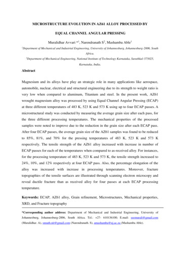
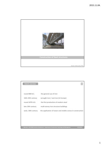
Roman-Era NailA Roman-era nail was found at a construction site in Vicenza, Italy. The head measured30-mm across by about 10-mm thick but the shaft was broken about 18-mm below thehead. It was encapsulated in a 1.5-inch diameter epoxy mount and polished. Etching with2% nital revealed that much of the head was carburized, although non-uniformly. Thecase, however, was not hardened by heat treatment and consisted of pearlite.Consequently, the nital etch was removed and it was etched with 4% picral, which yieldsmore uniform contrast with fully pearlitic structures than nital. This revealed that therewere small patches of as-quenched martensite – not seen using nital. Picral does not etchas-quenched martensite, while nital does. Figure 1 shows an example of such a patch.Figure 1 (left): Etching the Roman nail with 4% picral revealed several small patches ofas-quenched martensite in the carburized head. Picral does not etch as-quenchedmartensite.Figure 2 (right): Etching the same area with aqueous 10% sodium metabisulfite revealedthe structure of the as-quenched martensite (light brown in color), while the fine lamellarpearlite is multi-colored.As an alternative to nital, etching with aqueous 10% sodium metabisulfite will reveal thestructure of as-quenched martensite, Figure 2, which can also be documented in color.Use of polarized light and a sensitive tint filter enhances the coloration.The shaft of the nail was not carburized. The nail was made of wrought iron and Figure 3shows an excellent example of the slag that was present. Near the surfaces of the shaft,Figure 4, there were numerous mechanical twins (Neumann bands), but not in the center,Figure 5. These were more prevalent as the fracture was approached. This suggests thatthe nail broke, probably during winter, when it was being driven into some woodenobject.
Figure 3. Example of a large slag inclusion in the broken nail, 2% nital etch.Figure 4 (left): Numerous mechanical twins were observed near the outer surfaces of thenail (Beraha Sulfamic acid tint etch, polarized light plus sensitive tint).Figure 5 (right): Twinning was not observed in the center of the shaft (Klemm’s I tintetch, polarized light plus sensitive tint).Microindentation hardness testing was also performed on the nail. The ferritic regions inthe shaft had a Vickers hardness of 83 – 115. The very fine-grained ferrite in the head hada hardness of 125 – 130 HV. The fully pearlitic head regions had a hardness of 275 – 295HV due to the fine interlamellar structure. This hardness does not suggest, however, avery fast quench rate, as much higher hardnesses can be achieved in very fine pearlite.The martensitic patches had hardnesses of 620 – 862 HV, a substantial variation,suggesting carbon variations. As these patches are as-quenched martensite, the
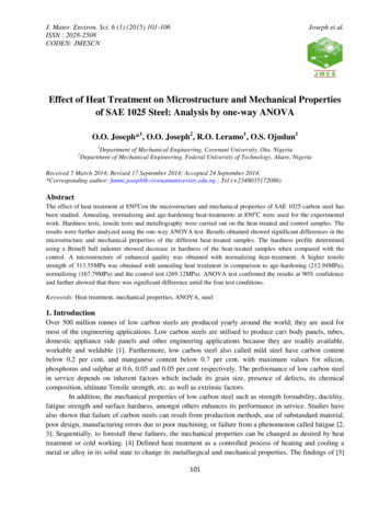
hardnesses correspond to at least 0.40% C in solution in the austenite (the martensite’sparent phase) for the patch at 620 HV to at least 0.60% C in solution in the austenite forthe 862 HV patch. No evidence of either excess carbon in the form of undissolvedcementite or retained austenite was found in these patches, suggesting an upper carbonlimit of about 0.7%.Japanese Helmet, 17th CenturyA section from the Japanese helmet shown in Figure 6 was removed by sawing. Beforethe cut was completed, the un-cut portion broke. SEM examination revealed severalfracture mechanisms and both intergranular and transgranular fracture surfaces, as shownin Figure 7. The section was mounted in epoxy resin and polished using the methoddescribed above. It was first examined after etching with 2% nital to reveal the grainstructure and with Klemm’s I, Figure 8. Boiling alkaline sodium picrate was used tocolor cementite particles observed in the grain boundaries, Figure 9. The steel had ahardness of 124.6 4.7 HV.Figure 6. 17th century Japanese helmet (Courtesy of the Higgins Armory Museum,Worcester, Massachusetts.
Figure 7. Examples of brittle fracture surfaces in the section prepared for the writer.Figure 8. Non-uniform grain structure of the helmet wrought iron; left – 2% nital; right –Klemm’s I reagent.Figure 9. Examples of grain boundary carbide networks in the helmet revealed usingboiling alkaline sodium picrate.
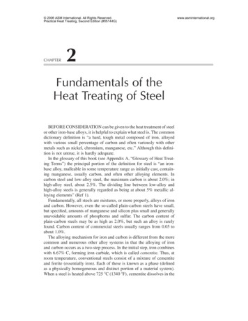
U.S.S. ArizonaThe battleship was built in the New York City Navy Yard starting March 16, 1914 andwas commissioned October 17, 1916. From 1929 to 1931, it was upgraded withsignificant changes to its superstructure, Figure 10. It was hit by the battleship Oklahomaand was in Pearl Harbor for repairs when sunk on December 7, 1941. 1177 crewmembersdied in the attack. Figure 11 shows the ship after the attack.Figure 10 (left): Battleship U.S.S. Arizona after the 1929-1931 rebuild.Figure 11 (right): The Arizona after the Japanese attack on Pearl Harbor.Figure 12 shows the bainitic microstructure of the deck plate with a hardness of 284.4 16.1 HV. This was a riveted ship, built long before welding was introduced. It would notbe welded easily. Figure 13 shows the microstructure of the plates in the stack whileFigure 14 shows the structure at the top and bottom of the 80-mm long rivet through thethree 24-mm thick stack plates.Figure 12: Bainitic microstructure of the deck plate; left: 4% picral; right: 10% sodiummetabisulfite.
Figure 13: Microstructure of the stack plate, consisting of equiaxed and acicular ferriteand bainite (4% picral etch).Figure 14: Microstructure at the top (left) and bottom (right) of the 80-mm long rivetshowing appreciable differences in heating temperature before riveting and cooling rateafter riveting (Beraha sodium thiosulfate-potassium metabisulfite tint etch).ConclusionsThis work has demonstrated the value of good metallographic techniques and choice ofthe best etchant for revealing the microstructure of historic iron-based objects. By carefulmetallographic work, one can learn a great deal about the manufacturing processes usedto make these objects.References1. H. Yakowitz, ASTM STP 480, Applications of Modern Metallographic Techniques,ASTM, Philadelphia (1970) p 49.
2. E. Beraha and B. Shpigler, Color Metallography, American Society for Metals,Metals Park, OH (1977).3. H. Gahm and F. Jeglitsch, Metal Progress (August 1981) p 48; and, MicrostructuralScience, 9, Elsevier North Holland, Inc., New York (1981) p 65.4. G. F. Vander Voort, Color Metallography, ASM Handbook, Vol. 9, Metallographyand Microstructures, ASM International, Materials Park, OH, 2004, p 493.5. G. F. Vander Voort, Metallography: Principles and Practice, McGraw-Hill Book Co.,New York (1984); and, ASM International, Materials Park, OH (1999).6. G. F. Vander Voort, Metal Progress 127, No. 4 (March 1985) p 31.7. E. Weck and E. Leistner, Metallographic Instructions for Colour Etching byImmersion, Part I: Klemm Colour Etching 77/I, D.V.S. Verlag GmbH, Düsseldorf,(1982).8. E. Weck and E. Leistner, Metallographic Instructions for Colour Etchants byImmersion, Part II: Beraha Colour Etchants and Their Different Variants 77/II, D.V.S. Verlag GmbH, Düsseldorf (1983).9. E. Weck and E. Leistner, Metallographic Instructions for Colour Etching byImmersion, Part III: Non-Ferrous Metals, Cemented Carbides and Ferrous Metals,Nickel-Base and Cobalt-Base Alloys 77/III, D. V. S. Verlag GmbH, Düsseldorf(1986).10. L. Beaujard, Comptes Rendus 233 (1951) p 653.11. L. Beaujard and J. Tordeux, Comptes Rendus 235 (1952) p 1304.12. L. Beaujard, Revue de Métallurgie 49 (July 1952) p 531.13. L. Beaujard, Metal Treatment and Drop Forging (November 1952) p 499.14. P. Lacombe and M. Mouflard, Métaux Corrosion-Industries, No. 340 (December1953) p 471.15. L. Beaujard and J. Tordeux, Revue de Métallurgie 52 (September 1955) p 750.16. B. V. Guellard, Metallurgia 54 (August 1956) p 93.17. J. R. Vilella and W. F. Kindle, Metal Progress 76 (December 1959) p 99.18. H. Klemm, Metallkundliche, Verlag Technik Berlin 45 (1952).19. H. Klemm, Practical Metallography 5 (April 1968), p 163.20. E. Beraha, Journal of the Iron and Steel Institute 203 (May 1965) p 454.21. E. Beraha, Journal of the Iron and Steel Institute 204 (March 1966) p 248.22. E. Beraha, Metal Progress 90 (September 1966) p 135.23. E. Beraha, Metal Progress 90 (October 1966) p 13.24. E. Beraha, Journal of the Iron and Steel Institute 205 (August 1967) p 866.25. E. Beraha, Practical Metallography 4 (August 1967) p 416.26. E. Beraha, Practical Metallography 5 (August 1968) p 443.27. E. Beraha, Practical Metallography 5 (September 1968) p 501.28. E. Beraha, Practical Metallography 7 (March 1970) p 131.29. E. Beraha, Practical Metallography 7 (May 1970) p 242.30. E. Beraha, Microstructures 2 (June/July 1970) p 23.31. E. Beraha, Practical Metallography 8 (September 1971) p 547.32. E. Beraha, Practical Metallography 11 (May 1974) p 271.33. A. O. Benscoter, J. R. Kilpatrick and A. R. Marder, Practical Metallography 15(December 1968) p 694.34. A. O. Benscoter, J. R. Kilpatrick and A. R. Marder, IMS Proceedings (1969) p 37.
35. J. R. Kilpatrick, A. O. Benscoter and A. R. Marder, Metal Progress (December 1971)p 79.36. J. R. Kilpatrick, Practical Metallography 28 (December 1991) p 649.37. P. Lichtenegger and R. Blöch, Practical Metallography 12 (1975) p 567.38. G. F. Vander Voort, Heat Treating Pr ogress 1 (April/May 2001) p 25.
Picral does not etch as-quenched martensite, while nital does. Figure 1 shows an example of such a patch. Figure 1 (left): Etching the Roman nail with 4% picral revealed several sm