Transcription
COMPUTER GRAPHICSSYLLABUSBASICS OF COMPUTER GRAPHICS: Introduction, What is computer Graphics?, Area of Computer Graphics, Designand Drawing, Animation Multimedia applications, Simulation, How are picturesactually stored and displayed, Difficulties for displaying pictures.GRAPHIC DEVICESCathode Ray Tube, Quality of Phosphors, CRTs for Color Display, BeamPenetration CRT, The Shadow - Mask CRT, Direct View Storage Tube, Tablets,The light Pen, Three Dimensional DevicesC Graphics BasicsGraphics programming, initializing the graphics, C Graphical functions, simpleprogramsSIMPLE LINE DRAWING METHODSPoint Plotting Techniques, Qualities of good line drawing algorithms, TheDigital Differential Analyzer (DDA), Bresenham’s Algorithm, Generation ofCirclesTWO DIMENSIONAL TRANSFORMATIONS and CLIPPING AND WINDOWINGWhat is transformation?, Matrix representation of points, Basic transformation,Need for Clipping and Windowing, Line Clipping Algorithms, The midpointsubdivision Method, Other Clipping Methods, Sutherland - HodgemanAlgorithm, Viewing TransformationsGRAPHICAL INPUT TECHNIQUESGraphical Input Techniques, Positioning Techniques, Positional Constraints,Rubber band TechniquesTHREE DIMENSIONAL GRAPHICSNeed for 3-Dimensional Imaging, Techniques for 3-Dimesional displaying,Parallel Projections, Perspective projection, Intensity cues, Stereoscope effect,Kinetic depth effect, ShadingSOLID AREA SCAN CONVERSION and Three Dimensional TransformationsSolid Area Scan Conversion, Scan Conversion of Polygons, AlgorithmSingularity,Three Dimensional transformation, Translations, Scaling, Rotation, ViewingTransformation, The Perspective, Algorithms, Three Dimensional Clipping,Perspective view of Cube1
COMPUTER GRAPHICSHIDDEN SURFACE REMOVALNeed for hidden surface removal, The Depth - Buffer Algorithm, Properties thathelp in reducing efforts, Scan Line coherence algorithm, Span - Coherencealgorithm, Area-Coherence Algorithms, Warnock’s Algorithm, PriorityAlgorithms2
COMPUTER GRAPHICSTable of The ContentsUNIT – 1BASICS OF COMPUTER GRAPHICS1.1 Introduction1.2 What is computer Graphics?1.3 Area of Computer Graphics1.3.1 Design and Drawing1.3.2 Animation1.3.3 Multimedia applications1.3.4 Simulation1.4 How are pictures actually stored and displayed1.5 Difficulties for displaying pictures1.6 Block Summary1.7 Review Question and Answers.UNIT 2GRAPHIC DEVICES2.1 Introduction2.2 Cathode Ray Tube2.3 Quality of Phosphors2.4 CRTs for Color Display2.5 Beam Penetration CRT2.6 The Shadow - Mask CRT2.7 Direct View Storage Tube2.8 Tablets2.9 The light Pen2.10Three Dimensional DevicesUnit 3C Graphics Introduction3.1 Introduction3.2 ‘C’ GRAPHICS FUNCTIONS3.3 C Graphics Programming Examples3
COMPUTER GRAPHICSUNIT 4SIMPLE LINE DRAWING METHODS4.1 Introduction4.2 Point Plotting Techniques4.3 Qualities of good line drawing algorithms4.5 The Digital Differential Analyzer (DDA)4.6 Bresenham’s Algorithm4.7 Generation of CirclesUNIT 5TWO DIMENSIONAL TRANSFORMATIONS5.1 Introduction5.2 What is transformation?5.3 Matrix representation of points5.4 Basic transformation5.5 Translation5.6 Rotation5.7 ScalingUNIT 6CLIPPING AND WINDOWING6.1 Introduction6.2 Need for Clipping and Windowing6.3 Line Clipping Algorithms6.4 The midpoint subdivision Method6.5 Other Clipping Methods6.6 Sutherland - Hodgeman Algorithm6.7 Viewing TransformationsUNIT 7GRAPHICAL INPUT TECHNIQUES7.1 Introduction7.2 Graphical Input Techniques7.3 Positioning Techniques7.4 Positional Constraints7.5 Rubber band TechniquesUNIT 8THREE DIMENSIONAL GRAPHICS8.1 INTRODUCTION8.2 Need for 3-Dimensional Imaging8.3 Techniques for 3-Dimesional displaying4
COMPUTER GRAPHICS8.48.58.68.78.88.9Parallel ProjectionsPerspective projectionIntensity cuesStereoscope effectKinetic depth effectShadingUNIT 9SOLID AREA SCAN CONVERSION9.1 Introduction9.2 Solid Area Scan Conversion9.3 Scan Conversion of Polygons9.4 Algorithm SingularityUNIT 10Three Dimensional Transformations10.1 Introduction10.2 Three-Dimensional transformation10.3 Translations10.4 Scaling10.5 Rotation10.6 Viewing Transformation10.7 The Perspective10.8 Algorithms10.9 Three Dimensional Clipping10.10 Perspective view of CubeUNIT 11HIDDEN SURFACE REMOVAL11.1 Introduction11.2 Need for hidden surface removal11.3 The Depth - Buffer Algorithm11.4 Properties that help in reducing efforts11.5 Scan Line coherence algorithm11.6 Span - Coherence algorithm11.7 Area-Coherence Algorithms11.8 Warnock’s Algorithm11.9 Priority Algorithms5
COMPUTER GRAPHICSUNIT – 1BASICS OF COMPUTER GRAPHICS1.1 Introduction1.2 What is computer Graphics?1.3 Area of Computer Graphics1.3.1 Design and Drawing1.3.2 Animation1.3.3 Multimedia applications1.3.4 Simulation1.4 How are pictures actually stored and displayed1.5 Difficulties for displaying pictures1.1 IntroductionIn this unit, you are introduced to the basics of computer graphics.To begin with we should know why one should study computer graphics. Itsareas of application include design of objects, animation, simulation etc.Though computer graphics gained importance after the introduction ofmonitors, these are several other input and output devices that are importantfor the concept of computer graphics. They include high-resolution colormonitors, light pens, joysticks, mouse etc. You will be introduced to theworking principles of them.The concept of computer graphics simply means identifying theirareas of the screen that are to be illuminated and those that should not be.Most of the regular figures like straight lines, circles etc, are represented bymathematical equations. Given such equations, the first aspect of computergraphics is to convert them to a sequence of points - picture cells or pixels thatare to be illuminated (in case of raster graphic display) or simply covert it to acurve that should be traced on the screen. Since many times these jobs haveto be very fast and efficient. You will be introduced to a number of suchalgorithms and also their limitations.We also look into the concept of transformations. Whenever asexisting is to be moved to a new place or say to be zoomed, the drawing is notdone again on the other hand; we only try to transform them. Simpletransformation matrices for various operations are also introduced. Further,often we may end up drawing pictures larger than these that can be6
COMPUTER GRAPHICSrepresented on the screen. In such cases, we have a mechanism of "clipping" itto the required dimensions. We also have schemes that fit a given picture into a"window" of suitable size and location.Further, since the computer is an "exact" device, in the sense itcannot approximate operations; sometimes it becomes difficult for the humanbeings to input exact values, like making the lines join exactly or the ends of acircle meeting perfectly etc. To take care of such cases, certain "constraints" areintroduced so that the computer can know what the input is about - or lookingat the other way, one cannot "approximate" things he is "constrained" to makethem perfect. Similarly there are several other graphical input techniques thatallow the user to interactively input the data, mostly drawings, without givingrise to ambiguities. These are also dealt with in this unit.1.2 What is computer Graphics?Computer graphics is an art of drawing pictures, lines, charts, etcusing computers with the help of programming. Computer graphics is made upof number of pixels. Pixel is the smallest graphical picture or unit representedon the computer screen. Basically there are two types of computer graphicsnamely1)Interactive computer graphics: It is the computer graphicsin which user can interact with the image on the computer screen. Here existtwo-way communication between the user and the image. The image is totallyunder the control of user. Example: Playing the computer game in thecomputer. Here user controls the image completely. According to the user wishimage makes the movements on the screen.2)Non-interactive computer graphics: it is the computergraphics in which user does not have any kind of control over the image. Imageis merely the product of static stored program and will work according to theinstructions given in the program linearly. The image is totally under thecontrol of program instructions not under the user. Example: screen savers.1.3 Areas of Computer GraphicsAs ancient says “ a pixel is worth thousand words”, graphics isessential everywhere to understand the things, concepts, etc easily. Computergraphics is useful in almost all part of our life. In the following sections we arediscussing some of the popular areas of computer graphics.1.3.1 Design and DrawingIn almost all areas of engineering, be it civil, mechanical,electronic etc., drawings are of prime importance. In fact, drawing is said to bethe language of engineers. The ability of computers to store complex drawings7
COMPUTER GRAPHICSand display them on demand was one of the major attractions for usingcomputers in graphics mode. Few samples in this area are given below.a)A mechanical engineer can make use of computergraphics to design nuts, bolts, gears etc.b)Civil engineer can construct the buildings, bridges,train tracks, roads etc on the computer and can see in different anglesand views before actually putting the foundation for them. It helps infinalizing the plans of these structures.c)A text tile designer designs different varieties ofdesigns through computer graphicsd)Electronics and electrical engineers design theircircuits, PCB designs easily through computer graphics.1.3.2 AnimationMaking the pictures to move on the graphical screen is calledanimation. Animation really makes the use of computers and computergraphics interesting. Animation brought the computers pretty close to theaverage individuals. It is the well known principle of moving pictures that asuccession of related pictures, when flashed with sufficient speed will make thesuccession of pictures appear to be moving. In movies, a sequence of suchpictures is shot and is displayed with sufficient speed to make them appearmoving. Computers can do it in another way. The properties of the picture canbe modified at a fairly fast rate to make it appear moving. For example, if ahand is to be moved, say, the successive positions of the hand at differentperiods of time can be computed and pictures showing the position of the handat these positions can be flashed on the screen. This led to the concept of“animation” or moving pictures. In the initial stages, animation was mainlyused in computer games.However, this led to a host of other possibilities. As we see later onin this course, computers not only allow you to display the figures but alsooffer you facilities to manipulate them in various ways – you can enlarge,reduce, rotate, twist, morph (make one picture gradually change to another –like an advertisement showing a cheetah change into a motor bike) and do awhole lot of other things. Thus, a whole lot of films made use of computers togenerate tricks. In fact, several advertisement films and cartons strips are builtwith no actors at all – only the computer generated pictures.Animation also plays very important role in training throughcomputer graphics. If you have been given a bicycle you might have learn toride it easily with little effort, but if you have been given a flight, automaticallyit needs the animated images to study the entire scenario of how flight takes8
COMPUTER GRAPHICSoff, on and handling it during flying, contacting with and getting the help fromcontrol room etc will be better explained using computers animation technique.1.3.3 Multimedia applicationsThe use of sound cards to make computers produce sound effectled to other uses of graphics. The concept of virtual reality, where in one can betaken through an unreal experience, like going through an unbuilt house (tosee how it feels inside, once it is built) are possible by the use of computergraphics technology. In fact the ability of computers to convert electronicsignals (0 & 1) to data and then on to figures and pictures has made it possiblefor us to get photographs of distant planets like mars being reproduced here onthe earth in almost real time.1.3.4 SimulationThe other revolutionary change that graphics made was in thearea of simulation. Basically simulation is a mockup of an environmentelsewhere to study or experience it. The availability of easily interactive devices(mouse is one of them, we are going to see a few other later in the course) madeit possible to build simulators. One example is of flight simulators, wherein thetrainee, sitting in front of a computer, can operate on the interactive devices asif he were operating on the flight controls and the changes he is expected to seeoutside his window are made to appear on the screen, so that he can masterthe skills of flight operations before actually trying his hand on the actualflights.The graphic capabilities of computers are used in a very largevariety of areas like criminology (to recreate faces of victims, assailants etc.,)medical fields (recreating pictures of internal cavities, using signals sent byminiature cameras), recreation of satellite pictures etc.1.4How are pictures actually stored and displayed?All operations on computers are in terms of 0’s and 1’s and hencefigures are also to be stored in terms of 0’s and 1’s. Thus a picture file, whenviewed inside the memory, can be no different from other files – a string of Osand 1s. However, their treatment when they are to be displayed makes thedifference.Pictures are actually formed with the help of frame-buffer displayas follows9
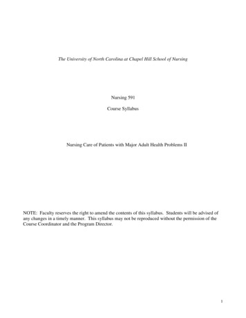
COMPUTER GRAPHICSFrame buffer display contains a frame buffer, which is a storagedevice and stores the image in terms of 0’s and 1’s. It contains the 0’s and 1’sin terms of 8’s, or multiples of 8’s in a row. These 0’s and 1’s will be read bydisplay controller one line at a time and sent to the screen after convertingthem from digital to analog. The display controller reads the contents of framebuffer one line at a time or entire digits at time. These digital images afterconverting into the analog will be displayed on the screen. The following figureillustrates this00000000 0000000001100110 1010110001000000 0000001001000000 0000001001000000 00000010001111111111111000000000 0000000000000000 0000000000000000 0000000000000000 00000000Scan LineFrame BufferMonitorDisplay ControllerFigures can be stored and drawn in two ways – either by linedrawing or by Raster graphic methods. In the line drawing scheme, the figuresare represented by equations – for example a straight line can be representedby the equation y mx c, a circle by x2 y2 r2 etc. If (x, y) are representativepoints, then all these (x,y) value pairs which satisfy the equations form a partof the figure while those that do not, lie outside the figure. Thus, to generateany figure, obviously the equation of the figure is to be known. Then all pointsthat satisfy the equation are evaluated. These are the points to be illuminatedon the screen.10
COMPUTER GRAPHICSaxxxxxxoYxXbPoints to be illuminatedA moving electronic beam, as we know illuminates the screen, orthe monitor. Whenever the beam is switched on, the electrons illuminate thephosphorescent screen and display a point. In the line drawing schemes, thisbeam is made to traverse the path of the figure to be traced and we get thefigure we need. For example, in the above cited example if the electron beam ismade to move from a to be along the points, we get the line.The raster scan mechanism uses a different technique and is oftenfound more convenient to manipulate and operate with. In this case, a "framebuffer", (a chunk of memory) is made to store the pixel values. (Remember, thescreen can be thought of as having beam made up of a number of horizontalrows of pixels (picture cells), each pixel representing a point on the picture. Infact the number of such horizontal and vertical points indicate higherresolutions and therefore better pictures. Typical resolutions are like 640 X480, 860 X 640, 1024 x 860 etc., where the figures indicate the number of rowsand the number of pixels along each row respectively on a computer screen(unlike in standard mathematics) the top left hand point indicates the origin orthe point (0,0) and the distances are measured horizontally and vertically asshown).11
COMPUTER GRAPHICSoxyNow, assuming a 1024 x 1024 point screen, any figure that is to bedisplayed within this space. The "frame buffer" stores "status" of each of thesepixels - say 0 indicates the pixel is off and hence is not a part of the picture and1 indicates it is a part of the picture, and is to be displayed. This data is usedto display the pictures.1.5Difficulties for displaying picturesUnfortunately, the concept of graphics of displaying pictures is lotmore complicated than what has been described so far - evaluate the pointsusing the equations, store them in a file and use raster graphics methods oruse simple line drawing algorithms. We will list a few of them before we closethis chapter.i) Stair case effects: Note that the pixel values arealways integers (0,0) (0,1) (0,2) - - - - - -- - -, but an algorithm todraw/manipulate pictures need not always return integer values.Suppose the point at which two line meet, say is at (1.4, 2.7). Whatdo we do? Common sense suggests that we round off the values, byusing any of the standard algorithms. Excellent. 1.4 gets rounded ofto 1 and 2.7 to 3. But another value of 1.6 say gets rounded off to 2and a value of 3.1 also gets rounded of to 3. So, what do we have?The pointer 1.4 and 1.6, which should be very close to each other,appear to be separated by a distance of 1 and not 0.2 in our figure,i.e. the smoothness of a figure joining these points is lost. Alternately,the points 2.7 and 3.1, instead of appearing to be different, appear tobe the same in our picture. A no. of such adjustments makes thefigure looks like a jagged one instead of a smooth figure.12
COMPUTER GRAPHICS(Why this is called a stair case effect and how we can reduce it, wewill see in due course)ii) Response time: Especially when talking of animation,the speed at which new calculations are made and the speed at whichthe screen can interact are extremely important. Imagine a runningbus, shown on the screen. Each new position of the bus (and it'ssurroundings, if needed) is to be calculated and sent to the screen andthe screen should delete the earlier position of the bus and display itsnew position. All this should happen at a speed that convinces theviewer that the vehicle is actually moving at the prescribed speed,otherwise a running vehicle would appear like a "walking" bus orworse a "piecewise movement” bus. For this, most the speed of thealgorithm and the speed of the display devices are extremelyimportant. Further, the entire operation should appear smooth andnot jerky otherwise, especially in simulation applications, the effectscan be dangers.iii) What happens when the size of the picture exceedsthe size of the screen?: Obviously, some areas of the picture are tobe cut off. But this involves certain considerations and needs to beaddressed by software. [Which we will discuss while discussing aboutclipping and windowing]iv) Can the user create pictures directly on thescreen?: Definitely all pictures can not be thought of in terms ofregular geometric figures and hence in terms of equations? Now,seeing a particular picture on the screen, the viewer wants to changeit slightly, say bend it slightly here, stretch it their etc. This may notsuit any regular equation? How should the system handle it?The subsequent blocks answer these and many otherquestions.13
COMPUTER GRAPHICSReview Questions1. The art of representing moving pictures is called 2. The concept of changing one picture gradually into another is called3. The combination of calculations, sound and pictures in computer is called4. Building a mock up of an environment with the aim of studying the same iscalled5. The equation of a straight line is given by6. A block of memory to store pixel values is called7. The number of pixels available for display of pictures is indicated by8. The concept of creating pictures directly on the screen is imediaSimulationy mx cFrame bufferResolutionInteractive graphics.14
COMPUTER GRAPHICSUnit 2GRAPHIC DEVICES2.1 Introduction2.2 Cathode Ray Tube2.3 Quality of Phosphors2.4 CRTs for Color Display2.5 Beam Penetration CRT2.6 The Shadow - Mask CRT2.7 Direct View Storage Tube2.8 Tablets2.9 The light Pen2.10 Three Dimensional Devices2.1 IntroductionDue to the widespread reorganization of the power and utility ofcomputer graphics in almost all fields, a broad range of graphics hardware andsoftware systems are available now. Graphics capabilities for both twodimensional and three-dimensional applications are now common on generalpurpose computers, including many hand-held calculators. These need widevariety of interactive devices.In this unit, we will look into some of the commonly used hardwaredevices in conjunction with graphics. While the normal concept of a CPU,Memory and I/O devices of a computer still holds good, we will beconcentrating more on the I/O devices. The special purpose output devices thatallow us to see pictures in color, for example, with different sizes, features etc.Also, once the picture is presented, the user may like to modify it interactively.So one should be able to point to specific portions of the display and changethem. Special input devices that allow such operations are also introduced.While ever changing technologies keep producing newer and newer products,what you are being introduced to here are trends of technology.2.2 The Cathode Ray Tube (CRT/Monitor)One of the basic and commonly used display devices is CathodeRay Tube (CRT). A cathode ray tube is based on the simple concept that anelectronic beam, when hits a phosphorescent surface, produces a beam of light(momentarily - though we later describe surfaces that produce light intensitieslashing over a period of time). Further, the beam of light itself can be focused toany point on the screen by using suitable electronic / magnetic fields. Thedirection and intensity of the fields will allow one to determine the extent of the15
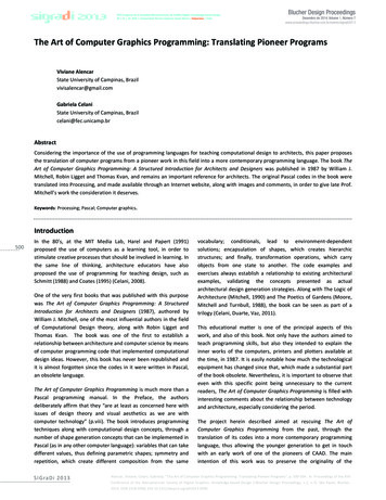
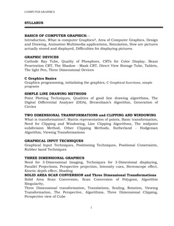
COMPUTER GRAPHICSdefection of the beam. Further these electronic / magnetic fields can be easilymanipulated by using suitable electric fields with this background. In followingsection we describe the structure and working of the simple CRT.Simple CRT makes use of a conical glass tube. At the narrow endof the glass tube an electronic gun is kept. This gun generates electrons thatwill be made to pass through the magnetic system called yoke. This magneticsystem is used for making the electronic beam to fall throughout the broadsurface of the glass tube. The broad surface of the glass tube contains a singlecoat of high quality phosphorus. This reflects the electronic beam makes it tofall on the computer screen.Fig. Basic Design of magnetic Deflection CRTA pair of focusing grids - one horizontal and another verticaldoes the actual focusing of the electronic beam on to the screen. Electronic ormagnetic fields operate these grids. Depending on the direction (positive ornegative) and the intensity of the fields applied to them, the beam is deflectedhorizontally (or vertically) and thus, by using a suitable combination of thesefocusing grids; the beam can be focused to any point on the screen.16
COMPUTER GRAPHICSSo, we now have a mechanism wherein any point on the screencan be illuminated (or made dark by simply switching off the beam).Hence, from a graphics point of view, any picture can betraced on the screen by the electron beam by suitably and continuouslymanipulating the focusing grids and we get to see the picture on the screen "Abasic graphic picture" of course, since the picture produced vanishes once thebeam is removed, to give the effect to continuity, we have to keep the beamretracing the picture continuously - (Refreshing).Quality of PhosphorsThe quality of graphic display depends on the quality of phosphorsused. The phosphors are usually chosen for their color characteristics andpersistence. Persistence is how long the picture will be visible on the screen,after it is first displayed. Most of the standards prescribe that the intensity ofthe picture should fall to 1/10 of its original intensity is less than 100milliseconds.The color of the phosphor is normally chosen as white, also itshould be of small grains, so that the resolution of the screen can be high.However, special types of monitors, to suit special applicationshave been devised, which may not confirm to the above standards. We will seea few of them in the next sections.2.3 CRTs for Color DisplayThis was one the earlier CRTs to produce color displays. Coatingphosphors of different compounds can produce different colored pictures. Butthe basic problem of graphics is not to produce a picture of a predeterminedcolor, but to produce color pictures, with the color characteristics chosen atrun time.The basic principle behind colored displays is that combining the 3basic colors –Red, Blue and Green, can produce every color. By choosingdifferent ratios of these three colors we can produce different colors - millionsof them in-fact. We also have basic phosphors, which can produce these basiccolors. So, one should have a technology to combine them in differentcombinations.17
COMPUTER GRAPHICS2.4 Beam Penetration CRTThis CRT is similar to the simple CRT, but it makes use of multicoloured phosphorus of number of layers.Each phosphorus layer isresponsible for one colour. All other arrangements are similar to simple CRT. Itcan produce a maximum of 4 to 5 coloursThe organization is something like this - The red, green and bluephosphorus are coated in layers - one behind the other. If a low speed beamstrikes the CRT, only the red colored phosphorus is activated, a slightlyaccelerated beam would activate both red and green (because it can penetratedeeper) and a much more activated one would add the blue component also.But the basic problem is a reliable technology to accelerate theelectronic beam to precise levels to get the exact colors - it is easier said thandone. However, a limited range of colors can be conveniently produced usingthe concept.2.5 The Shadow - Mask CRTThis works, again, on the principle of combining the basic colors Red, green and Blue - in suitable proportions to get a combination of colors,but it's principle is much more sophisticated and stable.The shadow mask CRT, instead of using one electron gun, uses 3different guns placed one by the side of the other to form a triangle or a "Delta"18
COMPUTER GRAPHICSas shown. Each pixel point on the screen is also made up of 3 types ofphosphors to produce red, blue and green colors. Just before the phosphorscreen is a metal screen, called a "shadow mask". This plate has holes placedstrategically, so that when the beams from the three electron guns are focusedon a particular pixel, they get focused on particular color producing pixel onlyi.e. If for convenience sake we can call the electronic beams as red, blue andgreen beams (though in practice the colors are produced by the phosphors,and until the beams hit the phosphor dots, they produce no colors), the metalholes focus the red beam onto the red color producing phosphor, blue beam onthe blue producing one etc. When focused on to a different pixel, the red beamagain focuses on to the red phosphor and so on.Now, unlike the beam penetration CRTs where the acceleration ofthe electron beam was being monitored, we now manipulate the intensity of the3 beams simultaneously. If the red beam is made more intense, we get more ofred color in the final combination etc. Since fine-tuning of the beam intensitiesis comparatively simple, we can get much more combination of colors than thebeam penetration case. In fact, one can have a matrix of combinations toproduce a wide variety of colors.The shadow mask CRT, though better than the beam penetrationCRT in performance, is not without it's disadvantages. Since three beams are tobe focused, the role of the "Shadow mask" becomes critical. If the focusing isnot achieved properly, the results tend to be poor. Also, since instead of onepixel point in a monochrome CRT now each pixel is made up of 3 points (for 3colors), the resolution of the CRT (no. of pixels) for a given screen size reduces.Another problem is that since the shadow mask blocks a portion of the beams(while focusing them through the holes) their intensities get reduced, thusreducing the overall brightness of the picture. To overcome this effect, thebeams will have to be produced at very high intensities to begin with. Also,since the 3 color points, though close to each other, are still not at the samepoint, the pictures tend to look like 3 colored pictures placed close by, ratherthan a single picture. Of course, this effect can be reduced by placing the dotsas close to one another as possible.The above displays are called refresh line drawing displays,because the picture vanishes (typically in about 100 Milli seconds ) and thepictures have to be continuously refreshed so that the human persistence ofvision makes them see as static pictures. They are costly on one hand and alsotend to flicker when complex pictures are displayed (Because refreshingbecause complex). These problems are partly overcome by devices withinherent storage devices - i.e. they continue to display the pictures, till they are19
COMPUTER GRAPHICSchanged or at least for several minutes without the need of being refreshed. Wesee one such device called the Direct View Storage Tube (DVST) below.2.6 Direct View Storage TubeConceptually the Direct View Storage Tube (DVST) behaves like aCRT with highly persistent phosphor. Pictures drawn on there will
1.3.2 Animation Making the pictures to move on the graphical screen is called animation. Animation really makes the use of computers and computer graphics interesting. Animation brought the computers pretty close to the average individuals.