Transcription
M-DUINO FAMILYM-Duino 21 User Guide:1 Index22.13Precautions. 5Arduino Board . 53.2Intended Audience . 53.3General Precautions . 5Specifications . 64.1General Specifications: . 64.2Performance Specification: . 65Before to connect:. 75.1Software interface . 75.2How to connect PLC Arduino to PC . 75.3How to connect PLC to power supply . 961Mechanical dimension . 43.14PageGeneral Description M-DUINO FAMILY product . 3M-duino 21/42/58 I/O Pinout: . 106.1A Zone connection (21/42/58 I/Os) . 106.2A Zone top (21/42/58 I/Os) . 116.3B Zone (21/42/58 I/Os) . 126.4B Zone top (21/42/58 I/Os) . 136.5C Zone (42/58 I/Os) . 146.6C Zone top (42/58 I/Os) . 156.7D Zone (58 I/Os) . 166.8D Zone top (58 I/Os) . 177M-Duino Arduino I/Os 5V pins . 17
88.1Communications / Interrupt Switch . 188.2Analog / Digital Configuration Switch . 1829PageSwitch configuration . 18Communications . 199.1I2C. 199.2TTL . 199.3SPI . 199.4RS-232 . 199.5RS-485 . 209.6Ethernet. 2110I/O technical details: . 229.Typical Connections . 2410.Connector details: . 2812.Mechanical Characteristics . 29
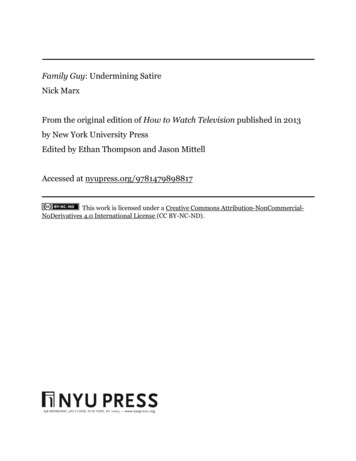
COMPACT PLC.2 General Description M-DUINO FAMILY productA compact PLC based in Open Source Hardware technology. With differentInput/Outputs Units.CONECTABLE PLC ARDUINO 24Vcc M-DUINOMODEL TYPE21 I/Os42 I/OsInput Voltage12- 24VdcI max.SizeClock SpeedFlash MemorySRAMEEPROM0,5A101x119.5x70.158 I/OsFuse protection (1A)Polarity protection101x119.5x94.7 101x119.5x119.316MHz256KB of which 8KB used by bootlader8KB4KB1CommunicationsTOTAL Input pointsTOTAL OutputpointsType of signalsAn/Dig Input 10bit(0-10Vcc)Digital Isolated Input(24Vcc)* Interrupt isolatedInput HS (24Vcc)Analog Output 8bit(0-10Vcc)Digital IsolatedOutput (24Vcc)Page3PWM IsolatedOutput 8bit (24Vcc)Expandability1I2C – Ethernet Port – USB – RS485 – RS232 -- SPI– (2x) Rx,Tx (Arduino x485-W51000-10VInput Impedance: 39KSeparated PCB ground5/12/24VdcI min: 2/6/12 mAGalvanic ISOLATION5/12/24VdcI min: 2/6/12 mAGalvanic ISOLATION0-10 VdcI max: 40 mASeparated PCB ground5/12/24 VdcI max: 0.3 AGalvanic ISOLATIONDiode Protected forRelay5/12/24 VdcI max: 0.3 AGalvanic ISOLATIONDiode Protected forRelayI2C - 127 elements - Serial Port RS232/RS485Pull-up resistance required (IS.ACI2C-4.7K)Ref. 23.03.16 MDUINO-GUIDE
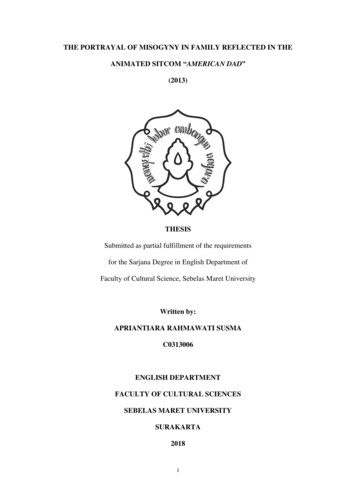
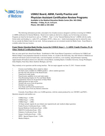
NO.base.58* By using this type of signal can no longer use Digital signal(24Vdc)You must to read product Datasheet.(1) IMPORTANT. Visit accessories/communication section.2.1 Mechanical dimensionM-Duino 21 I/OsM-Duino 42 I/OsPage4M-Duino 58 I/OsRef. 23.03.16 MDUINO-GUIDE
3 Precautions3.1 Arduino BoardAll M-duino family products use Arduino MEGA Board.3.2 Intended AudienceThis manual is intended for technicians, which must have knowledge on electrical systems.3.3 General PrecautionsThe user must operate M-Duino according to the performance specifications described in thismanual.Before using M-Duino under different conditions from the what is specified in this manual orintegrating M-Duino to nuclear control systems, railroad systems, aviation systems, vehicles,combustion systems, medical equipment, amusement machines, safety equipment and othersystems, machines, and equipment that may have a serious influence on lives and property ifused improperly, consult your INDUSTRIAL SHIELDS representative. Ensure that the rating andperformance characteristics of M-Duino are sufficient for the systems, machines, andequipment, and be sure to provide the systems, machines, and equipment double safetymechanisms. This manual provides information for programming and operating the M-Duino.Warnings: Unused pins should not be connected. Ignoring the directive may damage thecontroller.Improper use of this product may severely damage the controller.Refer to the controller’s User Guide regarding wiring considerations.Page5Before using this product, it is the responsibility of the user to read the product’s User Guideand all accompanying documentation.Ref. 23.03.16 MDUINO-GUIDE
4 Specifications4.1 General Specifications:ItemM-DUINO 21 IOsPower supplyvoltageDC power supplyOperatingvoltage rangeDC power supply11.4 to 25.4VdcPowerconsumptionDC power supply30VAC max.Externalpower supplyM-DUINO 58 IOs12 - 24VdcPower supplyvoltage24VdcPower supplyoutput capacity700MaInsulation resistanceM-DUINO 42 IOs20MΩ min.at 500Vdc between the AC terminals and the protective earth terminal.Dielectric strength2.300 VAC at 50/60 HZ for one minute with a leakage current of 10mA max. Between allthe external AC terminals and the protective earth terminal.Shock resistance80m/s2 in the X, Y and Z direction 2 times each.Ambient temperature (operating)Ambient humidity (operating)Ambient environment (operating)Ambient temperature (storage)0º to 45ºC10% to 90% (no condensation)With no corrosive gas-20º to 60ºCPower supply holding time2ms min.Weight445g max.542g max.850g max.4.2 Performance Specification:ItemArduino BoardARDUINO MEGA 2560Control methodStored program methodI/O control methodProgramming languageM-DUINO 42 IOsM-DUINO 58 IOsCombination of the cyclic scan and immediate refresh processing methods.Arduino IDE. Based on wiring (Wiring is an Open Source electronics platform composed of aprogramming language. “similar to the C”. lerATmega2560Flash Memory256kb of which 8 kb used by bootloaderProgram capacity (SRAM)8kbEEPROM4kbClock Speed16MHzClock Speed16MHzPage6M-DUINO 21 IOsRef. 23.03.16 MDUINO-GUIDE
5 Before to connect:5.1 Software interfaceIndustrial Shields programming environment is Arduino IDE.https://www.arduino.cc/en/Main/SoftwareYou can download start code for M-Duino at www.industrialshields.com , section EthernetPLCs /M-Duino / Document files.5.2 How to connect PLC Arduino to PC-Connect USB port from PLC to PC.NOTE:M-Duino Family use USB-B cable.-Open Arduino IDE interface:You can install with this link:http://arduino.cc/download.php?f /arduino-1.0.6-windows.exe-Select Arduino BoardNOTE:M-Duino Family use Arduino MEGA 2560.IMPORTANT: For M-duino Family you need set the AUTORESETswitch to on when uploading the program to Arduino Mega 2560).Page7 Ref. 23.03.16 MDUINO-GUIDE
-Select correct port.Page8IMPORTANT:Verify the USB port is detected:Ref. 23.03.16 MDUINO-GUIDE
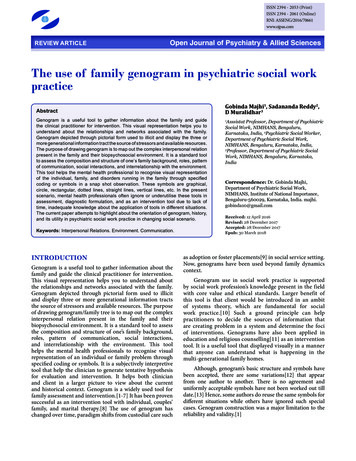
5.3How to connect PLC to power supply-MDuino Family PLC are 12-24Vdc supplied. IMPORTANT: The polarity IS NOTREVERSAL!Ensure that the live and GND connector of the power supply match the PLC.Ensure that the power supply mains output is not higher than 24Vdc.-Suggested power suppliersPage9* Not recommended for industrial applications. TheJack connector needs to be removed and use the liveand GND connectors.Ref. 23.03.16 MDUINO-GUIDE
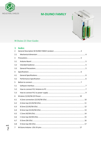
D ZONEC ZONEB ZONEA ZONED ZONEC ZONEB ZONEA ZONEA ZONEB ZONEC ZONED ZONE6 M-duino 21/42/58 I/O Pinout:6.1 A Zone connection (21/42/58 I/Os)Base(common unit)212010191817161514350 SO51 SI52 I2C/SSRX0/SSTX0/SSRX1/SSTX1/SSRX2(serial 2)TX2(serial 2)RX3/RS485/SSTX3/RS485/SSRS485RS485Arduino Pin/Select SPISPISPISPISPISPIArduino Pin/Select SPIGndGndConfiguration Switch* (see section 8 forCommunications configuration.Enabling Communications disable s someI/Os)Communication PinoutPower supply connectors(24Vdc – FunctionArduino PinM-DuinoConnectorA ZoneRef. 23.03.16 MDUINO-GUIDE
Base(common unit)FunctionArduino PinM-DuinoConnectorA EF2IOREF17VdcGnd3.3VdcGnd5VdcGnd6.2A Zone top (21/42/58 I/Os)Arduino PINArduino PINArduino PINGNDArduino PINGNDGNDPower led indicatorArduino Reset button*NOTE: Autoreset. Arduino mega has auto reset when using serial communication code. Set switch to OFF whenusing serial communication. When uploading code to Arduino Mega set switch to ON.Page11USB programmer connectorAutoreset*Ethernet connector(Arduino Mega)Ref. 23.03.16 MDUINO-GUIDE
6.3 B Zone (21/42/58 C26NC25NC24NC23NC22Function 2Arduino PinM-DuinoConnectorB ZoneAnalog/ Digital InAnalog/ Digital InAnalog/ Digital InAnalog/ Digital InAnalog/ Digital InAnalog/ Digital InGND I0.6Interrupt 1 InGND I0.5Interrupt 0 InGND I0.4Digital InputGND I0.3Digital InputGND I0.2Digital InputGND I0.1Digital InputGND I0.0Digital InputANALOG/DIGITAL InputsINTERRUPT Inputs (isolated)DIGITAL Inputs 5Q0.4Q0.3Q0.2Q0.1Q0.0GND6546544039383736Function 2Arduino PinM-DuinoConnectorB ZoneGNDAnalog OutAnalog OutAnalog OutExternal Isolated Out VdcExternal Isolated Out GndDigital/PWM OutDigital/PWM OutDigital/PWM OutDigital OutDigital OutDigital OutDigital OutDigital OutConfiguration Switch*(see section 8 select correctconfiguration for outputs).ANALOG OutputsVOLTAGE SUPPLY/REFERENCE forDIGITAL/PWM Outputs (isolated)Page12PWM/DIGITAL Outputs23See section 8 to select suitable switch configuration for (10-24Vdc/An-Dig) configurable I/Os.See section 8 to enable these connections.Ref. 23.03.16 MDUINO-GUIDE
6.4 B Zone top (21/42/58 I/Os)Page13Led indicator I/Os stateRef. 23.03.16 MDUINO-GUIDE
6.5 C Zone (42/58 C18NC31NC30NC29NC28NC27Function 4Arduino PinM-DuinoConnectorB ZoneAnalog/ Digital InAnalog/ Digital InAnalog/ Digital InAnalog/ Digital InAnalog/ Digital InAnalog/ Digital InGND I1.6Interrupt 4 InGND I1.5Interrupt 5 InGND I1.4Digital InputGND I1.3Digital InputGND I1.2Digital InputGND I1.1Digital InputGND I1.0Digital InputANALOG/DIGITAL InputsINTERRUPT Inputs (isolated)DIGITAL Inputs 5Q1.4Q1.3Q1.2Q1.1Q1.0GND7987984544434241Function 2Arduino PinM-DuinoConnectorB ZoneGNDAnalog OutAnalog OutAnalog OutExternal Isolated Out VdcExternal Isolated Out GndDigital/PWM OutDigital/PWM OutDigital/PWM OutDigital OutDigital OutDigital OutDigital OutDigital OutConfiguration Switch*(see section Error! Reference sourceot found. to select correctconfiguration for outputs).ANALOG OutputsVOLTAGE SUP
1 – Ethernet Port – USB – RS485 – RS232 -- SPI – (2x) Rx,Tx (Arduino pins) Max232-Max485-W5100 TOTAL Input points 13 26 36 TOTAL Output points 11 22 30 Type of signals An/Dig Input 10bit .