Transcription
Scope of WorkAnd SpecificationsRequest for Proposal - Part Two of FourSCOPE OF WORK AND SPECIFICATIONS REQUEST FORPROPOSAL
TABLE OF 014.015.016.017.018.0DEFINITIONS . 3INTRODUCTION . 4CONTRACTOR SCOPE OF WORK. 5EXISTING SITE DESIGN CONDITIONS . 9INDEPENDENT PROJECT DETAILS . 10APPROVED EQUIPMENT SUPPLIERS . 14PV MODULE SPECIFICATIONS . 15INVERTERS . 17COMBINER BOX . 18TRANSFORMERS (IF REQUIRED). 19COMMUNICATIONS . 20EQUIPMENT AND MATERIALS. 21ELECTRICAL INSTALLATION . 22MECHANICAL . 24SITE WORK . 25STRUCTURAL . 27COMMISSIONING AND PROJECT ACCEPTANCE TESTING . 28PROJECT AND CONSTRUCTION MANAGEMENT . 29SCOPE OF WORK AND SPECIFICATIONS REQUEST FORPROPOSAL
1.0DEFINITIONSAC/ac shall mean alternating current.Acceptance Test Procedures shall mean a document, or set of documents, agreed to by the Owner andContractor which detail the procedures to be completed during acceptance testing and requirements whichmust be met.Array shall mean a collection of solar modules connected in series, all tying into one Inverter Skid Assembly(ISA).Commissioning Process methodical testing procedures used as proof of operation as designed/intended.Contractor shall refer to the organization to which this Request for Proposal is addressed and who willengineer, procure, and construct the Project as specified within this document.DC/dc shall mean direct current.Energy Management System shall refer to a Graphical User interface developed with the intent to displaymetrics in a common language and display format suitable for the general public.Interconnection agreement (to be referenced once provided by coops)Inverter Skid Assembly (ISA) shall consist of the static power inverter, inverter step-up transformer (ifapplicable), associated cabling and grounding system.Owner shall refer to the Project entity whom the Contractor will enter into an agreement to complete allProject requirements as specified in this Scope of Work, and whom will ultimately take control of theProject.Perimeter Fence shall mean a physical security that is installed in such a manner as to surround theproperty allocated for the Project. The fence shall be contiguous without interruption (except for personneland vehicle gates).Point of Interconnection (POI) shall define the location of the physical electrical interconnection betweenOwner furnished electrical facilities and Contractor provided electrical facilities as part of this Project.Power Capacity Guarantee shall mean an agreement between the Contractor and Owner in which thecapacity of the Project is described. This capacity guarantee will include environmental and Projectconditions at which the capacity is tested.Power Capacity Test shall mean a power output capacity test to confirm that the Project has met the plantoutput guarantee. The test shall consist of a DC capacity test, an AC capacity test and a system losses test.Project shall mean the initiative to install a solar facility for long term operations.SCADA shall mean the Supervisory Control and Data Acquisition system, and shall include allmonitoring/control hardware and software, field instrumentation and communication devices.Scope of Work shall mean any and all activities necessary to complete the Project as specified.SCOPE OF WORK AND SPECIFICATIONS REQUEST FORPROPOSAL
Site shall mean the physical location where the solar facility will be installed. It is defined by theOwner.2.0INTRODUCTION2.1 Basics of DocumentA.This Scope of Work and Specifications document is designed to provide the Contractor with the detailsnecessary to engineer, procure and construct the facilities to the requirements desired by Owner.2.2 Bidder SubmittalsA.The Proposal Data Submittal Form document (separate section) shall be populated by the Contractorand submitted to the Owner for review. The Contractor is to populate the tables in the Proposal aSubmittal Form with information upon which the design is based. This Scope of Work andSpecifications document should be used as a guide for populating the Proposal a Submittal Form.2.3 Limits to ScopeA.The list of approved suppliers and specifications provided herein are intended to provide a collectionof suitable vendors and specifications important to primary equipment only. It is recognized here thatthere are more components to a functional installation than those listed below.SCOPE OF WORK AND SPECIFICATIONS REQUEST FORPROPOSAL
3.0CONTRACTOR SCOPE OF WORK3.1GeneralA.The Contractor shall furnish Project for Owner at the output level of energy production as proposedby the Contractor in the Proposal Form.B.The Project shall be capable of operating in accordance with the guidelines of this Request forProposal as well as subsequent contractual documents entered into between Contractor and Owner.C.The Contractor shall design and construct the Project in accordance with any contractual documentsand this Scope of Work and Specifications Document.D.The Contractor shall specify and furnish the equipment and materials which shall include, but not belimited to perimeter fences, PV modules, structural support systems, module string DC wiringharnesses, DC combiner boxes, inverters, inverter step-up transformers, ISAs, SCADA system, andancillary hardware required to connect and operate listed equipment.E.The Contractor shall provide Project design engineering and drawing packages for constructionpermitting, installation and “as-built” documentation. Engineering firm and Engineer of Record mustbe licensed in the Commonwealth of Virginia.F.The Contractor shall provide Project construction including all site/civil work, structural, electrical,mechanical and monitoring/control systems.G.The Contractor shall provide Project and construction management, including qualityassurance/quality control, site safety, site material control and management of all subcontractors.H.The Contractor shall provide Project commissioning and testing in accordance with this document.I.The Contractor shall provide the Owner training and Project sequence of operations; installation andmaintenance documentation.J.The Contractor shall be responsible for obtaining and providing to Owner, all permits necessary tosupport construction and Project installation.K.The Contractor shall be responsible for connection of the Project to electrical interface provided byOwner.L.Temporary Facilities1.If necessary, the Contractor shall be responsible for establishing and maintaining all restroom,lunchroom and other office and meeting areas for the duration of the construction andcommissioning portion of the Project.SCOPE OF WORK AND SPECIFICATIONS REQUEST FORPROPOSAL
2.3.4.5.6.3.2The Contractor shall provide temporary sanitary facilities with location at the discretion ofOwner. Contractor shall be responsible for decommissioning these temporary sanitaryfacilitates at the termination of construction.The Contractor shall maintain on-site dumpsters and personnel to maintain a clean and rubbishfree work site. Location of dumpsters at the discretion of Owner.The Contractor shall be responsible for permitting, installation and removal of all equipmentnecessary to satisfy water requirements for dust control purposes. Temporary water storagefacilities, if used, shall be removed and the area returned to existing grades and surfacing.The Contractor, if applicable, shall be responsible for designing and implementing temporarytraffic control measures as required by County or local agencies throughout constructionduration.Contractor may access and park at each construction site as necessary for construction; thetemporary parking areas shall be returned to design grades and surfacing at the termination ofconstruction. Contractor parking shall not interfere with normal member-owner business norOwner activities.M.The Contractor shall be responsible for site security throughout construction duration.N.The Contractor shall provide traffic management as necessary to ensure the safe entry to and exitfrom public roads for all vehicles and equipment.O.The Contractor shall, if applicable, conduct a Geotechnical Study suitable for the Project level designwork including bearing capacities, soil characteristics and infiltration requirements. Owner shallprovide access, if requested by Contractor, to site to perform structural testing.Owner Provided Facilities and ServicesA.The Owner will provide electrical panels as designated to accommodate Point of Interconnection(POI).B.The Owner will provide, if applicable, the Protective Device Coordination Study, Load Flow Study,Short Circuit Analysis and Grounding System study at the POI. Owner will furnish completed study toContractor.C.The Owner will provide access to building as required.D.The Owner will provide access to temporary electrical power where possible; Contractor shall beresponsible for providing power to any construction location where Owner is unable. In situationswhere there is conflict, Contractor will provide their own power generation consistent with Section3.6 C.SCOPE OF WORK AND SPECIFICATIONS REQUEST FORPROPOSAL
3.33.4Design CriteriaA.Project and individual components shall have a minimum design life of 25 years.B.Project shall be designed for fully autonomous operation.C.Project electrical design will be in compliance with applicable codes and standards listed underSection 3.6 unless otherwise noted.D.Project shall be so designed as to maximize kWh production or kW demand production and stated assuch in Proposal Data Submittal Form.E.Dissimilar metals in contact anywhere in the Project shall be avoided to eliminate the possibility ofgalvanic action. If unavoidable, proper transitional materials shall be used.F.During engineering design, Contractor shall work with the Owner when determining all signage,labeling and nomenclature.Projects and EquipmentA.Provisions shall be included in the design of all systems to allow the performance of all routinemaintenance without requiring a shutdown of the entire Project.B.3.5Contractor shall:1.Receive, inspect, store, unload, maintain, erect, clean, align and prepare all equipment inaccordance with equipment manufacturer’s instructions before initial operation.2.Provide lifting lugs on all equipment components or Project components requiringremoval for maintenance and weighing over 25 lbs.3.Select materials of construction and design equipment and systems to provide a minimumof a 25-year operating life at all operating conditions specified.4.Design the facility consistent with good engineering practice for solar generation facilities.5.Provide grounding lugs and ground all equipment.Operating CriteriaA.DC grid voltage: 600 volts DC or greater (with Owner approval), shall be grounded.B.AC grid voltage: (determined by site POI requirements as defined by the Owner). Panel NHW:480/277V, 150 A maximum. Panel NLW: 208/120V, 100 A maximum.C.DC & AC electrical systems under 1000V shall be radially configured. No redundancy is required.D.Convenience Power: 120VACE.Communications network: Ethernet via fiber optic within the arrays.SCOPE OF WORK AND SPECIFICATIONS REQUEST FORPROPOSAL
3.6Codes, Regulations and StandardsA. In the event that any applicable law or industry standard does not govern specific features of any itemof equipment and materials, temporary work or system, Contractor or Original Equipment Manufacturer(OEM) standards shall be applied, with Owner’s approval. Where local codes or ordinances will have animpact on the design, Owner and Contractor shall jointly address these with the local authorities havingjurisdiction.B. Listed herein are the principal codes and standards applicable in the design, fabrication and installationof the Project; these are not intended to be all encompassing. Where local codes or ordinances will havean impact on the construction, Contractor shall be responsible for meeting the codes or obtainingvariances from local authorities having jurisdiction.C. Contractor shall design and construct the Project in accordance with the following standards, asapplicable:1.ACI - American Concrete Institute2.AISC - American Institute of Steel Construction3.ANSI - American National Standards Institute4.AISI – American Iron and Steel Institute5.ASCE – American Society of Civil Engineers6.ASME – American Society of Mechanical Engineers7.ASTM - American Society for Testing and Materials8.IBC - International Building Code9.ICEA - Insulated Cable Engineers Association10. IEC - International Electrotechnical Commission11. IEEE - Institute of Electrical and Electronics Engineers12. ISA – Instrumentation Society of America13. NEC - National Electrical Code14. NEMA - National Electrical Manufacturers Association15. NESC - National Electrical Safety Code16. NETA - National Electrical Testing Association17. NFPA – National Fire Protection Association18. OSHA - Occupational Safety and Health Act19. UL – Underwriters’ LaboratoriesD. In the case where standards have conflicting requirements, Owner and Contractor will develop a mutualagreement of the prevailing standards.SCOPE OF WORK AND SPECIFICATIONS REQUEST FORPROPOSAL
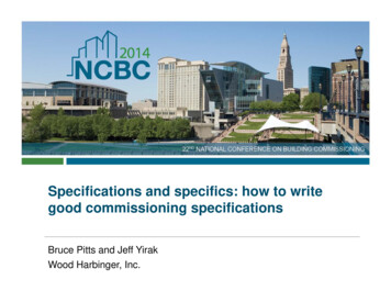
4.0EXISTING SITE DESIGN CONDITIONS4.1Site Physical LocationProject LocationTable 4-1. Project Location180 Oakwood Drive, Harrisonburg, VA 22801Figure 4-1. Vicinity Map of SiteSCOPE OF WORK AND SPECIFICATIONS REQUEST FORPROPOSAL
5.0INDEPENDENT PROJECT DETAILS5.15.2Parking Canopy ArrayA.The intent of this Project is to create a covered parking area for members and guests by utilizinginstalled PV panels as cover. If possible, canopy should extend over adjoining sidewalk.B.The structure may be of any style deemed structurally suitable; however, the canopy should cover theentire span of parking spaces without reduction or material change to any parking space or adjoiningsidewalk.C.The structure shall have no impact to ingress and egress around parking lot.D.Consideration will be given for aesthetic value and level of architectural fit to existing facilities.E.The array shall be connected to a common energy management system.F.If branding credit is part of a proposal, Contractor shall include its branding requirements within itsproposal. Please note that SVEC intends to provide to third parties, including its consumer members,comparative reports of the installation output, operations and maintenance cost as well as otherperformance and economic information about each installation. If an installation is branded toidentify the Contractor, such report will include the name of the Contractor in order that third partiesmay better compare one installation against another. For any installation that is not branded, SVECexpects to provide information about the manufacturers of components used, but not the name ofthe Contractor. Inclusion of branding credit as part of an installation shall constitute the agreement ofthe Contractor to the foregoing provision concerning the provision of such information. Use ofcomparative report, creation of derivative works based upon, distribution or display thereof, withoutthe prior written consent of Owner, is prohibited.Tracking ArrayA.The intent of this Project is to demonstrate a residential or small commercial scale array thatmaximizes energy output by tracking the movement of the sun and adjusting panel orientationaccordingly.B.The array shall be constructed using infrastructure components that would typically be found onresidential or small commercial installations unless otherwise identified in this specificationdocument.C.The array may be any shape or configuration as long as it is representative of a product reasonablyavailable to a residential member or small business owner.D.The array shall be connected to a common energy management system.SCOPE OF WORK AND SPECIFICATIONS REQUEST FORPROPOSAL
E.5.3If branding credit is part of a proposal, Contractor shall include its branding requirements within itsproposal. Please note that SVEC intends to provide to third parties, including its consumer members,comparative reports of the installation output, operations and maintenance cost as well as otherperformance and economic information about each installation. If an installation is branded toidentify the Contractor, such report will include the name of the Contractor in order that third partiesmay better compare one installation against another. For any installation that is not branded, SVECexpects to provide information about the manufacturers of components used, but not the name ofthe Contractor. Inclusion of branding credit as part of an installation shall constitute the agreement ofthe Contractor to the foregoing provision concerning the provision of such information. Use ofcomparative report, creation of derivative works based upon, distribution or display thereof, withoutthe prior written consent of Owner, is prohibited.Solar ShinglesA.The intent of this Project is to demonstrate residential and small commercial solar shingleinstallations. Project shall be built and installed in a manner closely resembling that of a residential orsmall commercial technique and style.B.The array shall be constructed using infrastructure components that would typically be found onresidential or small commercial installations unless otherwise identified in this specificationdocument.C.Please note that the roof for mounting is on a Facility that does not yet exist but will be designed andbuilt by SVEC to best meet the design submitted in the successful Contractor’s proposal.D.The array shall be connected to a common energy management system.E.If branding credit is part of a proposal, Contractor shall include its branding requirements within itsproposal. Please note that SVEC intends to provide to third parties, including its consumer members,comparative reports of the installation output, operations and maintenance cost as well as otherperformance and economic information about each installation. If an installation is branded toidentify the Contractor, such report will include the name of the Contractor in order that third partiesmay better compare one installation against another. For any installation that is not branded, SVECexpects to provide information about the manufacturers of components used, but not the name ofthe Contractor. Inclusion of branding credit as part of an installation shall constitute the agreement ofthe Contractor to the foregoing provision concerning the provision of such information. Use ofcomparative report, creation of derivative works based upon, distribution or display thereof, withoutthe prior written consent of Owner, is prohibited.SCOPE OF WORK AND SPECIFICATIONS REQUEST FORPROPOSAL
5.45.5Roof ArrayA.The intent of this Project is to replicate a standard PV array found on residential or small commercialbuildings. Project shall be built and installed in a manner closely resembling that of residential orsmall commercial technique and style.B.The array shall be constructed using infrastructure components that would typically be found onresidential or small commercial installations unless otherwise identified in this specificationdocument.C.Please note that the roof for mounting is on a Facility that does not yet exist but will be designed andbuilt by SVEC to best meet the design submitted in the successful Contractor’s proposal.D.The array shall be connected to a common energy management system.E.If branding credit is part of a proposal, Contractor shall include its branding requirements within itsproposal. Please note that SVEC intends to provide to third parties, including its consumer members,comparative reports of the installation output, operations and maintenance cost as well as otherperformance and economic information about each installation. If an installation is branded toidentify the Contractor, such report will include the name of the Contractor in order that third partiesmay better compare one installation against another. For any installation that is not branded, SVECexpects to provide information about the manufacturers of components used, but not the name ofthe Contractor. Inclusion of branding credit as part of an installation shall constitute the agreement ofthe Contractor to the foregoing provision concerning the provision of such information. Use ofcomparative report, creation of derivative works based upon, distribution or display thereof, withoutthe prior written consent of Owner, is prohibited.Energy StorageA.The intent of this Project is to demonstrate residential and small commercial energy storage. In thisinstance, because a closer inspection is possible, choices made for visibility, accessibility andcomponentry are very important.B.The energy storage site shall be constructed using infrastructure components that would typically befound on residential or small commercial installations unless otherwise identified in this specificationdocument.C.The Project shall be constructed with public safety in mind and shall have all componentry protectedfrom free and open access.D.The array shall be connected to a common energy management system.SCOPE OF WORK AND SPECIFICATIONS REQUEST FORPROPOSAL
E.If branding credit is part of a proposal, Contractor shall include its branding requirements within itsproposal. Please note that SVEC intends to provide to third parties, including its consumer members,comparative reports of the installation output, operations and maintenance cost as well as otherperformance and economic information about each installation. If an installation is branded toidentify the Contractor, such report will include the name of the Contractor in order that third partiesmay better compare one installation against another. For any installation that is not branded, SVECexpects to provide information about the manufacturers of components used, but not the name ofthe Contractor. Inclusion of branding credit as part of an installation shall constitute the agreement ofthe Contractor to the foregoing provision concerning the provision of such information. Use ofcomparative report, creation of derivative works based upon, distribution or display thereof, withoutthe prior written consent of Owner, is prohibited.SCOPE OF WORK AND SPECIFICATIONS REQUEST FORPROPOSAL
6.0APPROVED EQUIPMENT SUPPLIERS6.1Approved Equipment SuppliersTable 6-1. Approved Equipment SuppliersPV Modules SunPower REC Solar HanwhaSolarOneCombinerBoxes SolarBOS Shoals CooperCrouseHinds AMtec BentekInverters Fronius PowerOne SMA TMEIC SolarEdgeRackingSuppliers Solar FlexRack Unirac Sunlink PanelClawMonitoringSystem Draker ALSOEnergySolar Shingles SolarCityCertainTeedRGS EnergySunTergaEnergyStorage TeslaPowerwall LithiumIONSCOPE OF WORK AND SPECIFICATIONS REQUEST FORPROPOSAL
7.0Photovoltaic PV MODULE SPECIFICATIONS7.1PV Module SpecificationsTable 7-1. PV Module RequirementsPV Module SpecificationsRequirementsMaximum DC System Voltage1000VSustainable Wind Load90-MPHResistance to Environmental Damage (water, hail, ordamage, etc.)Per IEC 61215 / IEC 61646 requirementsGuaranteed Performance Degradation (25 years)No more than 3% of maximum power lostat the end of year 1. No greater than 0.7%reduction in power output at the end ofeach following year up to 25 years.UL/IEC Certifications1UL 1703and IEC 61730IEC 61215 (mono- or poly-crystalline)IEC 61646 (thin film)1The listed IEC/UL certifications are applicable to all technologies, except as noted. Several Nationally Recognized TestingLaboratories (NRTLs) besides UL are authorized to test to UL standards.7.2PV Module CharacteristicsA.Contractor must use only those panels as specified in Proposal Data Submittal Form.B.Contractor shall provide nominal module power rating at standard test conditions for modules tobe used in solar arrays, and their power rating tolerance.C.Contractor shall make at least three panels accessible at each Project location for adjustment byowner; Owner should be able to adjust panels up to 30 degrees.D.Contractor shall provide provisions at accessible panels in 7.2C for monitoring power quality.Owner should be able to interconnect monitoring device to all panels. The Owner utilizes PowerMonitoring Incorporated’s Eagle and Revolution style power quality recording devices.E.Glass laminates or glazing with low reflectivity are preferred.F.Manufactured to ISO9001:2000 and ISO 9001 quality and ISO14001:2004 environmentalstandards, NEC code requirements, and UL listing specifications.SCOPE OF WORK AND SPECIFICATIONS REQUEST FORPROPOSAL
7.37.4Panel Support StructureA.The module support structures shall be designed and constructed to provide a stable support systemfor the life of the Project. Module support structures shall meet all applicable codes and standards.B.Foundation shall be appropriate strength concrete (spread or augured) utilizing galvanized orequivalent corrosion-resistant steel members (corrosion-resistance defined by geo-technical report).C.The maximum support structure deflections shall prevent PV module and electrical system damageand shall not exceed allowable limits provided by the manufacturer and the IBC 2009 and ASCE 7-05codes.Solar ShinglesTable 7-4. Solar Shingle RequirementsSolar Shingle SpecificationsRequirementsMaximum DC System Voltage600VSustainable Wind RatingClass F ASTM D3161 (best wind rating)Resistance to Environmental Damage (water, hail, ordamage, etc.)Per IEC 61215 / IEC 61646 requirementsGuaranteed Performance Degradation (25 years)No more than 3% of maximum power lostat the end of year 1. No greater than 0.7%reduction in power output at the end ofeach following year up to 25 years.UL/IEC Certifications1UL 1703and IEC 61730UL 790 Class A Fire Rating ASTM D3161Class F IEC 61215IEC 61215 (mono- or poly-crystalline)IEC 61646 (thin film)Class 4 ANSI FM 4473 (best hail rating)1The listed IEC/UL certifications are applicable to all technologies, except as noted. Several Nationally Recognized TestingLaboratories (NRTLs) besides UL are authorized to test to UL standards.SCOPE OF WORK AND SPECIFICATIONS REQUEST FORPROPOSAL
8.0INVERTER8.1Inverter SpecificationsTable 8-1. – Inverter SpecificationsInverter SpecificationRequirementEfficiency97% minimum CEC efficiencyOutput Current Harmonics 3%WarrantyMinimum 15 yearsOperating TemperatureCapable of full rated output at 50 CMaximum DC voltage1000 (shall match Panel output)Guaranteed Performance Degradation (25 years)Inverters shall have a 25 year operating life.UL/IEC/IEEE CertificationsIEEE 1547UL 1741MODBUS, DNP3.0, SCADACommunications8.2Inverter CharacteristicsA.Contractor must use only those inverters as specified in Proposal Form. No alternatives will beaccepted unless approval by Owner is received prior to Contractor purchase.B.No more than one third of all panels that constitute any given Project may be on the sameinverter. The use of micro-inverters is permitted but discouraged for roof-mounted array.C.Preference for Inverters installed on tracking solar array to be hardened from all naturaldisasters.D.Inverters shall be physically mounted so as to avoid direct sun exposure and in a location thatoffers the best protection possible from other weather elements.SCOPE OF W
Oct 02, 2018 · Power Capacity Test shall mean a power output capacity test to confirm that the Project has met the plant output guarantee. The test shall consist of a DC capacity test, an AC capacity test and a system losses test. Project shall mean the initiative to install a