Transcription
GEInspection TechnologiesMobile Hardness TestingApplication Guide forHardness TestersDr. Stefan Frank
GE Inspection Technologies2
UltrasonicsMobile Hardness Testing –Application GuideDr. Stefan Frank1.1.11.21.3Introduction . 4What is hardness? . 4Why hardness testing? . 5On-site mobile hardness testing? . 52.2.12.2The UCI method (MIC 10, MIC 20) . 5The method . 5Selecting the suitable UCI probe . 63.3.13.2The Rebound method(DynaPOCKET, DynaMIC, MIC 20) . 8The method . 8Selection of the suitable impact device . 94.4.14.2The optical Through-Indenter-Viewing method (TIV) . 10The method . 10Selection of the suitable probe . 125.5.15.25.35.45.5The Hardness Testers – an Overlook . 13The DynaPOCKET . 13The DynaMIC . 13The MIC 10 . 13The MIC 20 . 14The TIV . 146.6.16.26.36.46.56.66.76.86.96.10The different methods in the field . 14Selecting the test method . 14Significance of indentation size . 15Relation between penetration depth and minimum thickness for coatings . 16Hardness testing on welds (HAZ) . 16Test piece mass requirements . 17Wall thickness requirements . 17Surface quality . 18Handling, alignment, and fixing . 18Calibration . 18Verifying instrument performance . 207.Summary and help in choosingthe suitable test method . 20The UCI method (MIC 20 / MIC 10) . 21Rebound method (MIC 20 / DynaMIC / DynaPOCKET) . 21Optical method – Through-Indenter-Viewing (TIV) . 21Fundamental questions to the user . 227.17.27.37.43
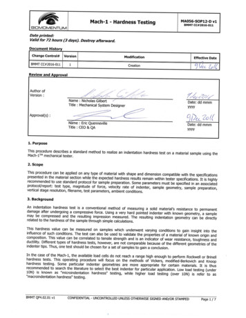
GE Inspection Technologies1. IntroductionMobile hardness testing is on the advance: in these times of cost pressureand higher quality requirements, it represents not only a quick but most of all aneconomical supplement to stationaryhardness testing in the modern production process. The application possibilitiesare far ranging - this refers to both largeand smaller components, especially atpositions which are difficult to access.Impedance) method and the dynamicrebound hardness testing method, as wellas the optical TIV (Through-IndenterViewing) method. The decision as to whichmethod is to be used depends on the testproblem. Krautkramer offers five instrument series for mobile hardness testing,operating according to the UCI, the rebound or the TIV methods: DynaPOCKET,DynaMIC, MIC 10, MIC 20, and TIV.field, e.g. hardness testing in the heataffected zone (HAZ) of welds.In addition to this, the subjects criticallydiscussed are the factors liable to influence the measured values, such as surface preparation at the test location orthe mass of parts to be tested as well astheir thickness.1.1 What is hardness?There are three different physical methodswhich are particularly recognized in thefield: the static UCI (Ultrasonic ContactThis Application Guide explains the basicprinciples of these test methods andcompares them, using examples from theWith regard to metallic materials, hardness has always been (and still is) a subject of much discussion among metallur-Fig. 1:Hardness testing using the MIC 20 in combination with the test supportMIC 227 and a UCI probe in the heat-affected zone (HAZ) of a weld.Fig. 2:Hardness testing with a rebound hardness tester (DynaMIC) on the drive wheelof a large hydraulic excavator.Fig. 3:Hardness testing using the DynaPOCKET on the chain of an open-pit miningexcavator.Fig. 4:Optical hardness testing using the TIV tester. Checking before final assembly.4
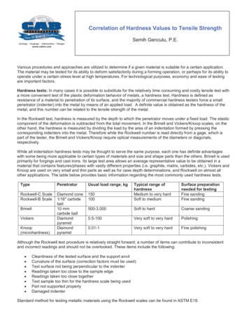
Ultrasonicsgists, engineers, and material scientists.It is no wonder therefore that there is awide range of definitions for the termhardness. Attributes like wear resistance,deformation behavior, tensile strength, aswell as modulus of elasticity or Young’smodulus are connected with the termhardness.An exact description of the method mustbe made if one wishes to compare theobtained readings with each other inorder to achieve a usable hardness value.However, if the reading depends on themethod, then the conclusion may quiteclearly be drawn that hardness is nophysical quantity but that it must be aparameter.Hardness testing is almost nondestructiveand in many cases used for determiningparameters to differentiate and describematerials. For example, hardness valuescan easily provide data on the strengthproperties of a material.The term hardness is generally understoodas being the resistance of a materialagainst the penetration of a body made ofa stronger material.Hardness is therefore not a fundamentalquantity of a material but always a response of the material to a certain load ortest method. A hardness value is calculated on the basis of the response of thematerial to this load.Depending on the test method, othernumerical values are then determinedwhich are due to and characterized by the shape and material of the indenter the type and size of the load,e.g. test load.The different test methods can be roughlydivided into two groups: Conversion relationships from nationaland international standards apply tocertain material groups to a limitedextent.The various conversion relationships, asspecified in standards DIN 50 150 andASTM E 140, are stored and can beselected in the instruments of theMICRODUR series (MIC 10 and MIC 20)and in the rebound hardness testers(DynaPOCKET, DynaMIC, MIC 20), aswell as in the optical TIV hardnesstester.a) Static test method:With this method of testing, the load isapplied statically or quasi-statically. Afterremoving the test load, the hardnessvalue is defined as a ratio of test load andthe surface or projected area of the permanent test indentation (Brinell, Vickers,or Knoop). In tests according to Rockwell,the hardness is determined by means ofthe permanent penetration depth of abody due to the test load.1.2 Why hardness testing?b) Dynamic test methodAs opposed to the static method, the loadis applied in the impact mode in thiscase, and the hardness is determined onthe basis of the indenter’s ”loss of energy”.1.3 On-site mobile hardness testing?It is normal practice – and often necessary – to indicate the hardness valuesusing another scale than the one used formeasuring them. The following shouldalways be taken into account regardingthis: There are no generally applicable relationships for the conversion of hardnessvalues from one to another Conversions are possible whenever theconversion relationship has been determined by statistically backed comparison measurementsWithin the production and assemblylines, the hardness of materials or components is mainly tested for two reasons:firstly, to determine the characteristics ofnew materials, and secondly, for thepurpose of quality assurance by meetingthe required specifications.Conventional hardness testers accordingto Rockwell, Brinell, or Vickers alwaysrequire the test piece be brought to thetester. As this is not always possible forpractical reasons and, most of all, forreasons of geometry, small and portablehardness testers were developed thatenable quick on-site testing on thecomponent.Different methods are applied here.Most of all the portable hardness testersaccording to the UCI, rebound, and TIVmethod are successfully used in practicaloperations in the field.2. The UCI method (MIC 10, MIC 20)Standardized according to ASTM A 10382.1 The methodAs in Vickers or Brinell hardness testing,the question as to the size of the testindentation left in the material by aVickers diamond after applying a fixedtest load also arises in Vickers hardnesstesting according to the Ultrasonic ContactImpedance method (UCI for short).However, the diagonals of the test indentation are not determined optically forthe hardness value as usual, but theindentation area is electronically detected5
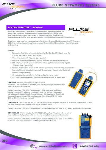
GE Inspection Technologiesby measuring the shift of an ultrasonicfrequency. The UCI method can be illustrated by a small imaginary experiment. AUCI probe essentially consists of a Vickersdiamond attached to the end of a metalrod (Fig. 5). This rod is excited into longitudinal oscillation by piezoelectric transducers. Imagine instead of the metal rod(we refer to it as oscillation rod) a largespiral spring held at one end and dlarger. Analogously, the largest frequencyshift is produced on soft test materials;the diamond penetrates deeper into thematerial leaving a large indentation.for all materials showing this modulus ofelasticity. The probes are factory-calibratedon low-alloy or unalloyed steels; however,modern test instruments can also bequickly calibrated to other materials, suchThe frequency shift is proportional to thesize of the test indentation produced bythe Vickers diamond. Therefore, thediagonals of the test indentation are notoptically determined for the hardnessvalue, as is usually done, but the indentation area is electronically detected bymeasuring the frequency shift – takingjust a few seconds.as titanium or copper, at the test location.This is the whole secret of UCI hardnesstesting: the frequency shift is proportionalto the size of the Vickers test indentation.Equation 1 describes this basic relation incomparison to the definition of the Vickershardness value.Vickers DiamondNaturally, such a frequency shift likewisedepends on the spring constant of oursmall ”atomic springs”.Fig. 5:Schematic description of the UCI method(Test load / Oscillation rod / Vickers diamond /Material to be tested).ing at a resonant frequency of 70 kHz atthe free end. At the very top of this spring,there is a contact plate, the Vickers dia
Hardness testing with a rebound hardness tester (DynaMIC) on the drive wheel of a large hydraulic excavator. Fig. 3: . Standardized according to ASTM A 1038. 6 GE Inspection Technologies 900 700 500 300 100 by measuring the shift of an ultrasonic frequency. The UCI method can be illus-trated by a small imaginary experiment. A UCI probe essentially consists of a Vickers diamond attached to .


![Hardness Tests [3]](/img/2/lmcm2-aula3.jpg)