Transcription
Data and ComputerCommunicationsChapter 4 –Transmission MediaDr. Bhargavi Goswami,HOD – CS, Associate Professor,Garden City College,Bangalore.
Transmission MediaCommunication channels in the animal world includetouch, sound, sight, and scent. Electric eels even useelectric pulses. Ravens also are very expressive. By acombination voice, patterns of feather erection andbody posture ravens communicate so clearly that anexperienced observer can identify anger, affection,hunger, curiosity, playfulness, fright, boldness, anddepression. —Mind of the Raven, Bernd Heinrich
Overview guided - wire / optical fibre unguided - wireless characteristics and quality determined bymedium and signal– in unguided media - bandwidth produced by theantenna is more important– in guided media - medium is more important key concerns are data rate and distance
Design Factors bandwidth– higher bandwidth gives higher data rate transmission impairments– eg. attenuation interference number of receivers in guided media– more receivers introduces more attenuation
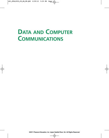
Electromagnetic Spectrum
The spectrum
Electromagnetic Spectrum with RangeSpecification
Transmission Characteristics of DelayRepeaterSpacingTwisted pair(with loading)0 to 3.5 kHz0.2 dB/km @1 kHz50 µs/km2 kmTwisted pairs(multi-paircables)Coaxial cable0 to 1 MHz0.7 dB/km @1 kHz5 µs/km2 km0 to 500 MHz7 dB/km @ 10MHz4 µs/km1 to 9 kmOptical fiber186 to 370THz0.2 to 0.5dB/km5 µs/km40 km
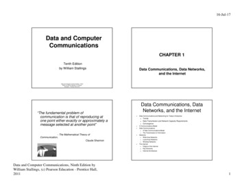
Twisted Pair
Twisted Pair - TransmissionCharacteristics analog– needs amplifiers every 5km to 6km digital– can use either analog or digital signals– needs a repeater every 2-3km limited distancelimited bandwidth (1MHz)limited data rate (100MHz)susceptible to interference and noise
Unshielded vs Shielded TP unshielded Twisted Pair (UTP)––––ordinary telephone wirecheapesteasiest to installsuffers from external EM interference shielded Twisted Pair (STP)– metal braid or sheathing that reduces interference– more expensive– harder to handle (thick, heavy) in a variety of categories - see EIA-568
UTP CategoriesCategory 3Class CCategory 5Class DCategory 5ECategory 6Class ECategory 7Class FBandwidth16 M Hz100 M Hz100 M Hz200 M Hz600 M HzCable TypeUTPUTP/FTPUTP/FTPUTP/FTPSSTPLink Cost(Cat 5 1)0.711.21.52.2
Comparison of Shielded andUnshielded Twisted PairAttenuation (dB per 100 m)Frequency(MHz)Category 3UTPCategory 5UTP12.64Near-end Crosstalk (dB)150-ohm STPCategory 3UTPCategory 5UTP150-ohm —21.4——31.3
Near End Crosstalk coupling of signal from one pair to another occurs when transmit signal entering the linkcouples back to receiving pair ie. near transmitted signal is picked up by nearreceiving pair
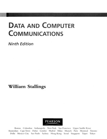
Coaxial Cable
Coaxial Cable - TransmissionCharacteristics superior frequency characteristics to TP performance limited by attenuation & noise analog signals– amplifiers every few km– closer if higher frequency– up to 500MHz digital signals– repeater every 1km– closer for higher data rates
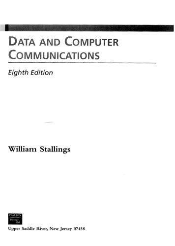
Optical Fiber
Optical Fiber - Benefits greater capacity– data rates of hundreds of Gbps smaller size & weightlower attenuationelectromagnetic isolationgreater repeater spacing– 10s of km at least
Optical Fiber - TransmissionCharacteristics uses total internal reflection to transmit light– effectively acts as wave guide for 1014 to 1015 Hz can use several different light sources– Light Emitting Diode (LED) cheaper, wider operating temp range, lasts longer– Injection Laser Diode (ILD) more efficient, has greater data rate relation of wavelength, type & data rate
Total Internal Reflection
Optical Fiber Transmission Modes
Dispersion in fiber optic
Frequency Utilization for FiberApplicationsFiber TypeApplicationM ultimodeLANSSingle modeVarious196 to 192CSingle modeWDM192 to 185LSingle modeWDMWave length (invacuum) range(nm)FrequencyRange (THz)820 to 900366 to 3331280 to 1350234 to 2221528 to 15611561 to 1620BandLabel
Attenuation in Guided Media
Comparison: UTP vs. FO Thickness (FO thicker than UTP) Weight (FO 1/100th of UTP) Photons vs. electrons (Electrons feel moreresistance, temperature, hence cross talk.Photons immune to them) Attenuation (FO need amplification after60km, UTP needs amplification every 5km) Erosion (Copper erode faster, Glass has lessenvironmental effects.
Comparison: UTP vs. FO Effect of EM interference (High on UTP and lesson FO) Leaking (High risk of eavesdropping and tappingattack in UTP then FO) Bandwidth (Far more in FO then UTP) Cost (FO far more expensive than UTP) Need for skilled engineer (in FO and not in UTP) Technology Complexity (High in FO and easy inUTP) Flexibility ( High in UTP and low in FO)
Wireless Transmission Frequencies 2GHz to 40GHz––––microwavehighly directionalpoint to pointsatellite 30MHz to 1GHz– omnidirectional– broadcast radio 3 x 10¹¹ to 2 x 10¹⁴– infrared– local
Antennas electrical conductor used to radiate or collectelectromagnetic energy transmission antenna– radio frequency energy from transmitter– converted to electromagnetic energy byy antenna– radiated into surrounding environment reception antenna– electromagnetic energy impinging on antenna– converted to radio frequency electrical energy– fed to receiver same antenna is often used for both purposes
Radiation Pattern power radiated in all directions not same performance in all directions– as seen in a radiation pattern diagram an isotropic antenna is a (theoretical) point inspace– radiates in all directions equally– with a spherical radiation pattern
Parabolic Reflective Antenna
Antenna Gain measure of directionality of antenna power output in particular direction versesthat produced by an isotropic antenna measured in decibels (dB) results in loss in power in another direction effective area relates to size and shape– related to gain
Terrestrial Microwave used for long haul telecommunicationsand short point-to-point linksrequires fewer repeaters but line of sightuse a parabolic dish to focus a narrow beam onto areceiver antenna 1-40GHz frequencies higher frequencies give higher data rates main source of loss is attenuation– distance, rainfall also interference
Satellite Microwave satellite is relay station receives on one frequency, amplifies or repeatssignal and transmits on another frequency– eg. uplink 5.925-6.425 GHz & downlink 3.7-4.2 GHz typically requires geo-stationary orbit– height of 35,784km– spaced at least 3-4 apart typical uses––––televisionlong distance telephoneprivate business networksglobal positioning
Satellite Point to Point Link
Satellite Broadcast Link
Broadcast Radio radio is 3kHz to 300GHz use broadcast radio, 30MHz - 1GHz, for:– FM radio– UHF and VHF television is omnidirectional still need line of sight suffers from multipath interference– reflections from land, water, other objects
Infrared modulate noncoherent infrared lightend line of sight (or reflection)are blocked by wallsno licenses requiredtypical uses– TV remote control– IRD port
Wireless PropagationGround Wave
Wireless PropagationSky Wave
Wireless PropagationLine of Sight
Refraction velocity of electromagnetic wave is a function ofdensity of material 3 x 10⁸ m/s in vacuum, less in anything else speed changes as move between media Index of refraction (refractive index) is– sin(incidence)/sin(refraction)– varies with wavelength have gradual bending if medium density varies– density of atmosphere decreases with height– results in bending towards earth of radio waves– hence optical and radio horizons differ
Line of Sight Transmission Free space loss– loss of signal with distance Atmospheric Absorption– from water vapour and oxygen absorption Multipath– multiple interfering signals from reflections Refraction– bending signal away from receiver
Free Space Loss
Multipath Interference
Fiber Optics v/sv/s Practically? Single fiber has, more potentialbandwidth than all thesatellites ever launchedbut, this bandwidth is notavailable to most userspractically. Mobile Communication? Terrestrial fiber optic linksare of no use to them.SatelliteWireWirelessWith satellites, it ispractical for a user toerect an antenna onthe roof of the buildingand completely bypasswired system to gethigh bandwidth.satellite linkspotentially are mostsuitable for mobilecommunication.By:Bhargavi H. Goswami,Email:bhargavigoswami@gmail.com45
Fiber Optics v/sv/s Broadcasting?Not suitable for broadcasting. Cost?Costly for communication inplaces with hostile terrain or apoorly developed terrestrialinfrastructure. Right of Way? for laying fiberis difficult or undulyexpensive. Rapid Deployment?Fiber optics is costly in termsof skilled engineers.SatelliteWireWireless Message sent by satellite canbe received by thousands ofground stations at once. Bestsuited. Launching one satellite wascheaper than stringingthousands of undersea cablesamong the 13,677 islands. Instead launching onesatellite would be cheaper. When rapid deployment iscritical, as in militarycommunication systems intime of war, satellites wineasilyBy:Bhargavi H. Goswami,Email:bhargavigoswami@gmail.com46
MULTIPLEXING MUX – DEMUX TYPES– FREQUENCY DIVISION MULTIPLEXING– TIME DIVISION MULTIPLEXING ASYNCHRONOUS V/S SYNCHRONOUS TDM– WAVELENGTH DIVISION MULTIPLEXING– SONET MULTIPLEXING (SYNCHRONOUS – OPTICALNETWORK MULTIPLEXING)
CAL TDM
WDM – Wavelength DivisionMultiplexing
SONET – Synchronous OpticalNetwork Is an Optical Transmission Interface havingsynchronous network. Proposed by Bellcore and standardized by ANSI. Used in North America, while Japan and Europeuses SDH – Synchronous Digital Hierarchy. Solved issue of interoperability among thevendors and technology. Single clock is used to handle the timings. Used for Broadcast services, particularly ATM andB-ISDN.
Synchronous Transport Signal
PHYSICAL CONFIGURATION STS Multiplexers Regenerators Add/Drop Multiplexers
Physical Configuration
Frame Structure Has 9 rows of 90 bytes i.e 9x90 810 bytes. Transmitted from left to right and top to bottom. TOH – First three columns are called TransportOverhead. SPE – Remaining 87 columns are called SynchronousPayload Envelop POH – First column of SPE is called Payload Overhead. Every SONET Frame repeats every 125 microsecondsno matter what is line speed. As line rate goes up, SONET frame gets bigger, to keepframe rate at 8000 frames/sec.
CIRCUIT SWITCHINGMULTISTAGECROSSBAR
CROSSBAR SWITCH
MULTI STAGE SWITCH
ERROR DETECTION ANDCORRECTION TYPES OF ERRORSBIT STUFFINGBYTE STUFFINGBURST ERRORSVRCLRCCRCHAMMING CODECHECKSUM
Types of Errors:By: Prof. Bhargavi Goswami,Email:bhargavigoswami@gmail.com,Mob: 917383816996
Single-bit errorBy: Prof. Bhargavi Goswami,Email:bhargavigoswami@gmail.com,Mob: 917383816996
Multiple-bit errorBy: Prof. Bhargavi Goswami,Email:bhargavigoswami@gmail.com,Mob: 917383816996
Burst errorBy: Prof. Bhargavi Goswami,Email:bhargavigoswami@gmail.com,Mob: 917383816996
XORing of two single bits or twowords To detect or correct errors, we need to sendextra (redundant) bits with data.By: Prof. Bhargavi Goswami,Email:bhargavigoswami@gmail.com,Mob: 917383816996
Detection Methods: Detection methods– VRC(Vertical Redundancy Check)– LRC(Longitudinal Redundancy)– CRC(Cyclical redundancy Check)– ChecksumBy: Prof. Bhargavi Goswami,Email:bhargavigoswami@gmail.com,Mob: 917383816996
VRC VRC(Vertical Redundancy Check)– A parity bit is added to every data unit so that thetotal number of 1s(including the parity bit)becomes even for even-parity check or odd forodd-parity check– VRC can detect all single-bit errors.– It can detect multiple-bit or burst errors only thetotal number of errors is odd. Even parity VRC concept is given in next figBy: Prof. Bhargavi Goswami,Email:bhargavigoswami@gmail.com,Mob: 917383816996
VRCBy: Prof. Bhargavi Goswami,Email:bhargavigoswami@gmail.com,Mob: 917383816996
LRC LRC(Longitudinal Redundancy Check)– Parity bits of all the positions are assembled into anew data unit, which is added to the end of thedata blockBy: Prof. Bhargavi Goswami,Email:bhargavigoswami@gmail.com,Mob: 917383816996
VRC & LRCBy: Prof. Bhargavi Goswami,Email:bhargavigoswami@gmail.com,Mob: 917383816996
CRC Generator CRC generator uses modular-2 division.Binary Divisionin a CRC Generator
CRC CheckerBinary Divisionin aCRC CheckerBy: Prof. Bhargavi Goswami,Email:bhargavigoswami@gmail.com,Mob: 917383816996
As per text book:Calculation of the polynomial code checksum.By: Prof. Bhargavi Goswami,Email:bhargavigoswami@gmail.com,Mob: 917383816996
Checksum: Checksum is used by the higher layer protocols And is based on the concept of redundancy(VRC, LRC,CRC . Hamming code) To create the checksum the sender does the following:– The unit is divided into K sections, each of n bits.– Section 1 and 2 are added together using one’scomplement.– Section 3 is added to the result of the previous step.– Section 4 is added to the result of the previous step.– The process repeats until section k is added to the result ofthe previous step.– The final result is complemented to make the checksum.
Checksum Example
Hamming code and Error Redundancy for error handling m data bits and r redundant bits for m r bits only one correct value of r for agiven m one correct bit pattern requires m r incorrectpatterns m r 1 2r7 bit data 4 bit redundant bits makes it 11
Hamming code calculations
R1,R2,R3 and R4 calculations R1 represents the parity of M1, M2, M4, M5,and M7 M1 M2 M4 M5 M7 1 0 0 1 0 0 0
Data and Computer Communications Dr. Bhargavi Goswami, HOD –CS, Associate Professor, Garden City College, Bangalore. Chapter 4 –Transmission Media . Transmission Media Communication channels in the animal world include touch, sound, sight, and scent. Electric eels even use electric pulses. Ravens also are very expressive. By a combination voice, patterns of feather erection and body .