Transcription
Available online at www.worldscientificnews.comWSN 54 (2016) 27-39EISSN 2392-2192Evolutionary Analysis of GSM, UMTS and LTEMobile Network ArchitecturesPaschal A. Ochang1,a, Philip J. Irving2,b1Department of Computer Science, Federal University Lafia, Nasarawa State, Nigeria2Department of Computing, Engineering and Technology, University of Sunderland,Sunderland, SR6 0DD, United Kingdoma,bE-mail address: pascosoft@gmail.com , phil.irving@sunderland.ac.ukABSTRACTThe Global System for Mobile Communications (GSM) which is a standard for 2G (secondgeneration) cellular networks has created an avenue for the development of 3G (third generation) and4G (fourth Generation) cellular network standards such as Universal Mobile TelecommunicationsSystem (UMTS) and long term evolution (LTE). With the deployment of new technologies still on theway, the era beyond 3G and 4G requires that cellular and radio technologies need to work togetherforming highly heterogeneous networks, therefore this paper analyses already existing cellularnetwork technologies such as LTE, GSM and UMTS in order to give a general understanding of theirarchitectures, functional and evolutional dependencies and also to provide an evolutionary trend and aclear overview of the support provided for other telecommunications infrastructure.Keywords: GSM; UMTS; LTE; Network Achitecture; Security; Bandwidth1. INTRODUCTIONMobile communication and wireless technologies have seen a major significant growthover the recent years (Gu and Peng, 2010) due to the numerous advantages they contribute notonly to the economic sector but to other sectors as well. This significant evolution of mobilecommunications technologies can be categorised into generations respectively which include1G, 2G, 3G and 4G (Poole, 2006). Section 2 of this report discusses the GSM architecture,
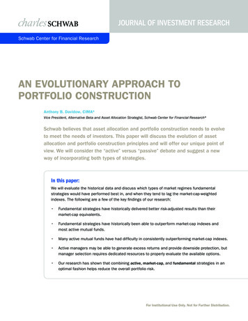
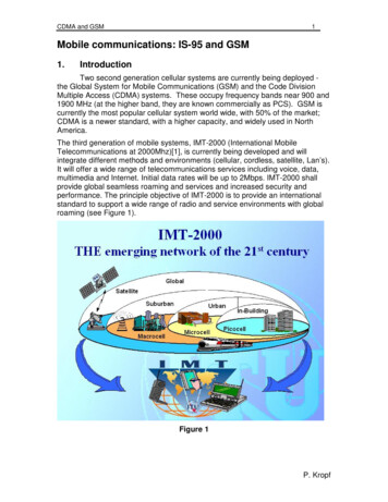
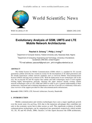
World Scientific News 54 (2016) 27-39while section 3 discusses the UMTS architecture. Section 4 gives an overview of the LTEarchitecture, while section 5 gives an overview of the comparison between all architectures2. GSMThe introduction of mobile communications can be traced back to the early 1980s whenthe first analogue systems where being implemented in the US, this led to the development ofadvance mobile phone system (AMPS) which commenced operation in Chicago with themajor objectives of interstate roaming and handset compatibility (Fuentelsaz et al., 2008).Development also took place in Europe with the introduction of the total accesscommunication system (TACS) and in 1985 two companies were give operational licencesnamely British Telecommunications and Racal Vodaphone (Poole, 2006). Most of thesesystems were analogue systems that consisted of mixed technologies which differ betweencountries and had many drawbacks such as continental roaming could not be achieved alsothe analogue systems could not handle the increase in capacity of users. In 1982 a committeeof technical personnel referred to as Group Special Mobile (GSM) was set up by the EuropeanConference of Postal and Telecommunications Administrations (CEPT) to implement amobile communications technology that was digital, pan-European in nature and allowedroaming throughout the whole European continent while providing improved capacity whencompared to analogue systems. In 1991 the GSM standard was deployed using the 900 MHzband (Gu and Peng, 2010).2. 1. GSM SYSTEM ARCHITECTUREFigure 1. GSM Network Architecture.-28-
World Scientific News 54 (2016) 27-39The GSM architecture is made up of majorly three subsystems which include theMobile Station, Network and Switching Subsystem (NNS), and the Base Station Subsystem(BSS) (Gu and Peng, 2010). The GSM architecture also contains an intelligent networksubsystem (IN) which adds more functionality to a network in terms of prepaid serviceswhereby a subscriber can fund his or her account for making calls and sending short messageservices (SMS) (Sauter, 2011).2. 2. MOBILE STATIONThe mobile station consists of all the equipment or software required by a subscriber tocommunicate with the network. It consists of the mobile equipment (ME) and the subscriberidentity module (SIM). The ME which is also referred to as the mobile phone consists of aunique international mobile equipment identity (IMEI) which is used to validate and identifyit on the network. The SIM is a memory module which contains all the details of a user on anetwork; it contains an international mobile subscriber identity (IMSI) which identifies ituniquely. It also consist of Authentication key (Ki) used for authentication (Qureshi andUsman, 2011).2. 3. BASE STATION SUBSYTEM (BSS)The BSS which is also known as the radio network or the radio subsystem manages allthe radio transmission paths between the mobile stations (MS) and other subsystems in theGSM architecture (Sauter, 2011).The BSS consist of base station controllers (BSC) and thebase transceiver stations (BTS).2. 3. 1. Base Transceiver StationThe base transceiver station contains the facilities for transmitting and receiving radiosignals. The transmission path between the mobile station and the base station is referred to asthe Um interface.2. 3. 2. GSM Air InterfaceGSM employs two methods in other to allow simultaneous communication between aBTS and multiple subscribers, this include the frequency division multiple access (FDMA)which enables subscribers to communicate with the BTS using multiple frequencies, while theother method is the TDMA which enables subscribers to be multiplexed using time bydividing carriers into frames. Each of the frames contains eight time slots that are physicallyindependent, and each of the time frames is referred to as a burst. If a subscriber was allocateda timeslot of 2 that meant the caller can only send and receive during this burst. The time slotsare arranged into logical channels for the purpose of transmission of user data, some thislogical channels include the traffic channel (TCH) which is used for the transmission ofdigitised voice, fast associated control channel (FACCH) which is used when urgentsignalling messages are needed to be sent such as handover command, The Slow AssociatedControl Channel (SACCH) which is used for the measurement of signal quality and providesvalues for power control and handover decisions.-29-
World Scientific News 54 (2016) 27-392. 3. 3. Base Station Controller (BSC)The BSC carries out establishment, maintenance and release of connections that areestablished on a cell. The BSC also handles radio channel allocation and controls BTS to BTShandover. When a subscriber has an incoming call the BSC is paged by the MSC which inturns check its local database in other to determine the cell which a subscriber that needs to bepaged belongs to. When a message is received by the mobile station, a channel assignmentmessage is also sent by the mobile station. When the mobile station has exchanged necessaryinformation with the MSC, a request is sent by the MSC to the BSC for a voice channel to beassigned to the mobile station. The BSC then checks if a traffic channel is available andactivates it on the BTS then the mobile station switches to the TCH and the FCCH and usesthe FCCH to notify the BTS that it is now on that TCH. When there is low signal reception bythe mobile station, the BSC is responsible for sending power control messages to the BTSwhich in turn forwards it to the mobile station so that the mobile station can increase thepower of the antennas.2. 4. NETWORK AND SWITCHING SUBSYTEM (NSS)The NSS is the core component of the GSM architecture which is responsible for callswitching, end to end calls, mobility management of subscribers and communication withother networks such as PSTN and ISDN. The components of the NSS include the MobileSwitching Centre (MSC), Home Location Register (HLR), Visitor Location Register (VLR),Equipment Identity Register (EIR), and Authentication Centre (AUC).2. 4. 1. Mobile Switching Centre (MSC)The MSC is a central part of the NSS which provides call set up, call routing, callswitching and handoff. when there is no connection between the network and the mobiledevice, the MSC reports a change of location to the network so that the mobile station can bereachable by incoming calls, also when a subscriber changes location while a call isestablished, the MSC is part of the component that makes sure the call is rerouted to the nextcell without interrupting the call. The MSC can be classified under different contextdepending on roles, for example a Gateway MSC is responsible for interfacing with the PSTNand it is also responsible for locating a currently called subscriber.2. 4. 2. Home Location Register (HLR)The HLR is a central database or subscriber database of all subscribers that areauthorized to use the GSM network; it also contains the individual services that are associatedwith a subscriber. The HLR contains details of every SIM on the network and uses the IMSIof the SIM as a primary key for searching its records.2. 4. 3. Visitor Location Register (VLR)The VLR is a database of all subscribers who roam into an area served by an MSC butdo not reside there (Chitrapu and Aghili, 2007). When a Subscriber roams into the area of anMSC, the subscriber details are copied into the VLR while the original details are stored inthe HLR; this is used to reduce the amount of signalling done between the MSC and the HLR.-30-
World Scientific News 54 (2016) 27-392. 4. 4. Equipment Identity Register (EIR)The EIR contains a list of mobile phones that are either monitored, stolen or have beenbanned from the network the mobile phones are identified by their IMEI (international mobileequipment identity). When a mobile station tries to access a network the IMEI is comparedwith the register of the EIR and the response or status message can be (a) white-listed: in thiscase the mobile station is allowed to connect (b) grey-listed: in this case the mobile station isbeing monitored (c) black-listed: the mobile station is not allowed to connect because it haseither been reported stolen or not approved.2. 4. 5. Authentication Centre (AUC)The Authentication Centre (AUC) is an element that is used to authenticate the SIMcard of a subscriber on the network. The AUC contains the key per subscriber called Ki whichis also contained in the SIM card in other to prevent SIM card cloning on the network.2. 5. BANDWIDTH OFFERED BY GSMGSM uses TDMA combined with a channel bandwidth of 200 kHz to provide a highlevel of spectrum efficiency (Poole, 2006).GSM uses Frequency division duplexing to pairchannels for both uplink to the BTS and downlink to the mobile devices respectively. Initiallyin Europe, GSM was configured to use the 900MHz band with an uplink of 890 to 915 MHzand a downlink of 935 to 960 MHz to provide a bandwidth of 25MHz which can be split into125 channels of 200 kHz each (Sauter, 2011). Due to the increase in demand for channels inthe European countries the 1800 MHz band was introduced and had an uplink of 1710 to 1785MHz and downlink of 1805 to 1880 MHz, this provided a bandwidth of 75 MHz whichprovided 375 channels. The 1900 and 850 MHz bands were also introduced in NorthAmerica.2. 6. AUTHENTICATION IN GSMWhen a mobile station is switched on, it sends its IMSI after which it is assigned aTMSI. The MSC and VLR gets it’s real IMSI and sends it to the AuC which then finds itsauthentication key (Ki). By using the Ki with ciphering key generation algorithm (A8) andAuthentication algorithm (A3), a ciphering key (Kc) and a signed result (SRES) and randomnumber (RAND) which is called an authentication triplet is generated (Qureshi and Usman,2011). The triplet is sent back to the MSC and VLR who in turn send the SRES and theRAND to the mobile station while retaining the Kc. The mobile station uses the A3 and A8algorithm to generate SRES and Kc using the Ki in the SIM and the received RAND, and thenSRES is sent back to the VLR and MSC which in turn compares it with the SRES that wasreceived from the AuC and HLR. Authentication is successful if the match between the SRESis successful2. 7. ROAMING IN GSMThe roaming service allows a subscriber to travel out of his home network to a visitednetwork and still use the services provided by his home network. When a subscriber moves toa visited network, the visiting network performs a location update (LU) through the SignallingConnection Control Part (SCCP) gateway which is part of the signalling system 7 (SS7)-31-
World Scientific News 54 (2016) 27-39(Assawaboonmee et al., 2004), then authentication is also carried out and the roamingsubscriber profiles are stored in the VLR. The details of the subscriber will also be updated inthe HLR of the subscriber’s home network. This allows the subscriber to use the visitednetwork as his home network.2. 8. CALL SECURITY IN GSMCall security and privacy in GSM is achieved by ciphering or encrypting each burst ofdata or voice stream using the A5/1 encryption algorithm (Gold, 2011). Data and speechencryption is only done on the air interface between the BTS and the Mobile station. Toencrypt the data stream a Kc is calculated by the SIM card and AuC by using the Ki andRAND as input parameters for the A8 algorithm, then the A5 ciphering algorithm uses the Kcto generate a 114bit sequenced which is XOR with the data stream (Sauter, 2011). This 114bit is changed for every burst in other to enhance security.3. UNIVERSAL MOBILE TELECOMMUNICATIONS SYSTEM (UMTS)UMTS is regarded as a third generation (3G) wireless communication system that actsas a successor to the second generation (2G) communication technologies and is an evolvedversion of GSM GPRS and EDGE (Poole, 2006). The GSM network was used to providevoice capabilities to subscribers but they was need to support the increasing number ofsubscribers while providing high speed data services. The Third Generation PartnershipProgramme (3GPP) was formed to oversee the implementation of a system that could offersuppor
GSM uses TDMA combined with a channel bandwidth of 200 kHz to provide a high level of spectrum efficiency (Poole, 2006).GSM uses Frequency division duplexing to pair channels for both uplink to the BTS and downlink to the mobile devices respectively.