Transcription
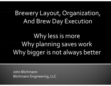
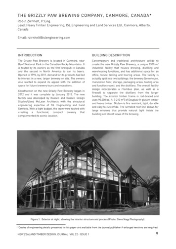
THE GRI ZZLY PAW BREW ING CO MPANY, CANMORE, CANADA*Robin Zirnhelt, P.Eng.Lead, Heavy Timber Engineering, ISL Engineering and Land Services Ltd., Canmore, Alberta,CanadaEmail: rzirnhelt@islengineering.comINTRODUCTIONBUILDING DESCRIPTIONThe Grizzly Paw Brewery is located in Canmore, nearBanff National Park in the Canadian Rocky Mountains. Itis touted by its owners as the first brewpub in Canadaand the second in North America to can its beers.Opened in 1996, by 2011, demand for its products had ledto interest in a new, larger brewery on site. The ownersalso wanted to expand its appeal with the addition ofspace for future brewery tours and receptions.Contemporary and traditional architecture collide tocreate the new Grizzly Paw Brewery, a unique 1300 m2industrial facility that houses brewing, distilling andwarehousing functions, and has additional space for anoffice, future tasting and touring areas. The facility isactually split into two buildings: the brewery (brewhouse,maturation floor, storage, packaging areas, tasting areaand function room); and the distillery. The overall facilitydesign incorporates a rhombus plan, as well as afirewall to separate the distillery from the largerbuilding. The exterior timber frame is rod-braced anduses 90,000 bd. ft. ( 210 m3) of Douglas fir glulam timberand heavy timber. Glulam is fire resistant, light, durableand easy to customize. The serrated roof line allows forlarge windows that provide natural light inside thebuilding and street views of the brewing.Construction on the new Grizzly Paw Brewery began in2012 and it was complete by January 2013. The newfacility was developed by Russell and Russell DesignStudios/Lloyd McLean Architects with the structuralengineering expertise of ISL Engineering and LandServices. With a tight budget, the team were tasked withcreating a functional, compact brewery thatcomplemented its scenic location.Figure 1. Exterior at night, showing the interior structure and process (Photo: Steve Nagy Photography).*Copies of engineering details presented in this paper are available from the journal publisher if enlarged versions are required.NEW ZEALAND TIMBER DESIGN JOURNAL VOL 22 · ISSUE 19
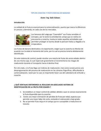
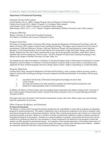
This multiple gabled roof is wood decked with 29 mmfire retardant treated, tongue-and-groove plywood. Theinterior mezzanine floor was constructed of concrete–steel composite materials, elevating some of theprocess equipment and tanks 6 m above the main slab,while holding the heavy weight and providing a viewthrough the high windows (Figure 2).CONCEPTThe building frame was originally envisioned to be ofsteel (Figure 3), as that was expected to be the most cost-effective material for a light industrial building.However, cost estimates for the design came in higherthan the budget. The cost of steel, combined with therhombus layout of the building and the complicatedFigure 2. Interior steel mezzanine and process equipment (Photo: Steve Nagy Photography).Figure 3. Original steel structure.10NEW ZEALAND TIMBER DESIGN JOURNAL VOL 22 · ISSUE 1
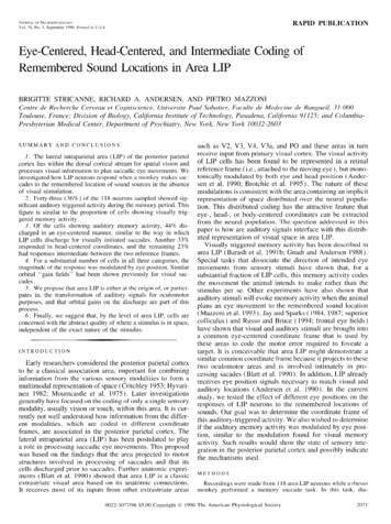
Figure 4. Revised timber structure (2011 Canadian Timber Frames Limited).geometry of the serrated roof line made it costly tomanufacture in conventional open web steel joists andwide flange steel sections. The complicated roofstructure is probably the main reason why timber beatout the original pre-engineered steel trusses and steelsuperstructure in price. In contrast, modern timbersoftware and manufacturing processes make it possibleto visualise, design and ultimately fabricate complexshapes in timber.After the steel budget numbers came in, an alternativeconceptual design was proposed to bring the project inon-budget: exposed heavy timber construction (Figure4). Preliminary sizing and ball park estimates for thisalternative looked promising. Timber specialists werebrought in for the work, including the heavy timberstructural engineering expertise of ISL Engineering andLand Services (then Cascade Engineering).The greatest contributor to cost in the new design wasthe volume of lumber. The timber manufacturer,Canadian Timberframes Limited, used BuildingInformation Modelling (BIM) to create a 3D modelshowing member sizes and connection arrangements.This 3D modelling helped the team calculate costs andassess the cost of changes to the design. The model wasused from concept redesign through to fabrication. Itcontributed to shop drawings, helped the team visualisehow the framing fit together to avoid conflicts, and wasused to control the Computer Numerical Control (CNC)machinery that fabricated the timber components. Boththe labour cost and the cost of fabricating complicatedNEW ZEALAND TIMBER DESIGN JOURNAL VOL 22 · ISSUE 1designs were significantly reduced by using thiscomputer-controlled modelling, design and fabrication.In terms of other software used, the structuralengineering team used RISA-3D software for structuralanalysis. WoodWorks software was used for memberdesign and connection capacities.The structuraldrawings were completed in REVIT, while the timbermodelling and CNC interfacing was completed incadwork (3D software for timber construction).CONNECTIONSThe structural engineering design team and the timbermanufacturer collaborated on the design concepts forthe heavy timber connections. The concepts for almostall of these connections were worked out in a couple ofhours through an in-person meeting using a live model,with sketch pads and calculators in-hand. This designcharrette considered the following connection types: oak pegged mortise and tenon (Figure 5) milled wood dovetails (Figure 6) standard birdsmouth notches (Figure 7) housings (Figure 8) steel shear keys (Figure 9) embedded threaded tension rod connections(Figure 10)11
conventional bolted and pinned connections(Figure 11) custom fabricated steel brackets (Figure 12) European self-tapping timber screws (Figure 13) highly engineered milled aluminum dovetailconnectors (Figure 14) field welded base plate connectors which allowedfor adjustment after survey of cast-in weld plates(Figure 15)Dove tail 1” long c/w1 pair of Assy Plus VG 8.0x200mmInstalled at 45 from the inside8x8Each connection was reviewed for structural capacity,constructability and design appearance in its location. Byconsidering a range of connection types, the integrateddesign and construction team was able to determine theright connection for the right application, rather than the“one size fits all” approach often employed by engineers.We believe that this approach leads to optimal timbersolutions (simple connections where simple makessense, complex connections only when needed), andultimately limits the number of custom steel fabricationsrequired and makes the design faster to install.Figure 6. Milled wood dovetails. (Source: 2011 CanadianTimber Frames Limited)Figure 5. Oak pegged mortise and tenon connection.(Source: 2011 Canadian Timber Frames Limited)12Figure 7. Standard birdsmouth notches. (Source: 2011Canadian Timber Frames Limited)NEW ZEALAND TIMBER DESIGN JOURNAL VOL 22 · ISSUE 1
Figure 8. Housings (Source: 2011 Canadian TimberFrames Limited).Figure 10. Embedded threaded tension rod connections(Source: 2011 Canadian Timber Frames Limited).Figure 9. Steel shear keys (Source: 2011 Canadian Timber Frames Limited).NEW ZEALAND TIMBER DESIGN JOURNAL VOL 22 · ISSUE 113
Figure 11. Conventional bolted and pinned connections(Source: 2011 Canadian Timber Frames Limited).Figure 13. European self-tapping timber screws(Source: 2011 Canadian Timber Frames Limited).Figure 12. Custom fabricated steel brackets (Source: 2011 Canadian Timber Frames Limited).14NEW ZEALAND TIMBER DESIGN JOURNAL VOL 22 · ISSUE 1
Figure 14. Highly engineered milled aluminum dovetail connectors (Source: 2011 Canadian Timber Frames Limited).Figure 15. Field welded base plate connectors which allowed for adjustment after survey of cast-in weld plates(Source: 2011 Canadian Timber Frames Limited).ROOFA combination of glulam timber and solid sawn timberwas used to save material costs, according to theavailability of section sizes and lengths. Larger section,long-span beams and tall columns were specified to beof Douglas-fir glulam timber, while smaller sections the wind girts, rafters and drag struts - were to beconstructed of heavy, solid sawn timber, which wasreadily available in the neighbouring province of BritishColumbia.NEW ZEALAND TIMBER DESIGN JOURNAL VOL 22 · ISSUE 1Supported by wood beams and purlins, the roof includesthe following components: roof tiles made of recycled rubber with a slateappearance peel-and-stick membrane 11 mm OSB sheathing air space with 38 x 140 mm wood strapping andcounter-strapping15
ISO board insulationLOADING 29 mm fire retardant treated, tongue-and-grooveplywood heavy-timber structureThe timber was protected from the elements in anumber of ways. Timber on the exterior of the buildingenvelope comprises most of the timber usage, and this isprotected by wide overhangs. Details were incorporatedin the timber design to prevent water from collecting andcausing damage, and the connectors were galvanized.The infill panels are steel stud frame walls with apainted metal skin and insulated with spray foam. Theinterior timberwork started on concrete pedestals tokeep it well above the floor as the floor is sprayed in thecleaning process for the brewery.The plywood for the timber roof deck spanned the 1.2 mrafter spacing, and with special valley and ridgefastening was designed to be a large flexible diaphragmdelivering the loads to the perimeter walls and rodtension-braced frames. The building needed towithstand the gravity loading of mountain snow withconsiderable valley drifting accumulations as well as alarge tank loading for the brewing tanks on the upperlevel. Lateral load design was primarily governed bywind, but the large dead load of the tanks and theconcrete topping on the upper level brought seismicloading into some governing load combinations. Wherethere were very high loads, structural steel was used.For example, structural steel was used to support someof the heaviest process equipment on the brewery floor.FIRE SAFETYSUMMARYThe Grizzly Paw Brewery was designed as two separatebuildings in accordance with the province’s building code(Alberta Building Code). The brewery building isclassified as Medium Hazard Industrial. The smallerbuilding, housing the distillery, is classified as HighHazard Industrial occupancy and is separated from themain brewery building with a core-filled, concrete blockwall, which acts as a 4-hour firewall.Rather than the “one size fits all” approach oftenemployed by engineers, the collaboration betweenstructural engineer and timber manufacturer enabledthe right connection to be selected for the rightapplication. This limited the number of custom steelfabrications required and ultimately made the designfaster to install and economically feasible. While thesteel fabricators had found the roofline too complicatedto be cost effective, the timber manufacturer’sexperience and computer-controlled shaping equipmentmade it not only possible but also economical. Computer-controlled modelling, design and fabrication reducedcosts for labour and for fabricating complicated designs.Timber was a better fit for implementing the design,suited the mountain architectural style of the town, andprovided the brewery with an attractive feature duringpublic tours.Equipment access for fire-fighting is provided on twosides. Automatic fire sprinklers were not needed for thesize of the building area and number of storeys. The totalbuilding floor area (developed) for the Brewery is1,295.5 m2 , with the breakdown as follows: Main level - 693.5 m2 Middle level (undeveloped) - 432 m2 Upper level - 170 m2For the Distillery (single-storey, undeveloped), the floorarea is 50 m2 .Most of the structure is constructed of timber. Sometimber members were slightly increased in size so thatthey would qualify as heavy timber construction andprovide a charring layer for the fire performancerequirements. The size increase allowed them to meetthe Fire Code requirements for combustibleconstruction with a 45-minute fire rating.The timber roof deck uses a thicker 29 mm tongue-andgroove plywood that was specially ordered to meet therequired 45-minute fire resistance rating. Thus, thisplywood construction meets the minimum requirementsfor heavy timber construction. Where structural steelwas used to support the heaviest process equipment, therequired 45-minute fire resistance rating was achievedwith a cementitious layer applied by spray.16As construction wrapped up in January 2013, even thebuilder noted, “The building was a positive experience.There were no surprises. The wood construction was10% more economical than the steel options priced. Theassembly of the pre-manufactured members andconnections went smoothly. In those rare cases wheresmall adjustments were required on site, they were easyto do. The project could have been completed ahead ofschedule but there was a delay in acquiring some of thebrewing equipment. (Source: Canadian Wood Council/Wood WORKS 2013.)The new Grizzly Paw Brewery opened to production inApril 2013 and started running tours in July of that year.The building is functional, compact and compliments itsscenic location.The author would like to acknowledge the Grizzly PawBrewery case study by Canadian Wood Council / WoodWORKS! ALBERTA (2013), which informed this article.NEW ZEALAND TIMBER DESIGN JOURNAL VOL 22 · ISSUE 1
superstructure in price. In contrast, modern timber software and manufacturing processes make it possible to visualise, design and ultimately fabricate complex . engineering team used RISA-3D software for structural analysis. WoodWorks softw