Transcription
Rectifier Design and AnalysisRectifier Design and AnalysisThis document describes the operation and design of AC line operated rectifiercircuits. Both theory of operation and detailed design procedures are included,neither of which require complex differential equations for analysis of the transcendental relationships.While this is not a mathematically "pure" analysis, it is based on the principles oftranscendental relationships using graphical integration, initial conditions andsolution of discontinuous functions; providing useable results for the actualconstruction of working systems as well as an intuitive understanding of thevoltages and currents involved. The complex mathematical analysis normallyrequired to predict circuit behavior has left many, otherwise technically savoy,individuals relying on handbook data without understanding the actual interactions involved.This document is written for individuals with a technical understanding of (min)veifiO0-iCtc0tc0'tc0tfto23 //iCtoT /tc0'tft 0t 0Disclaimer:This document, associated technical descriptions and design information comprise a W5BWC Electronics project done exclusively for John L. KeithW5BWC. This is an original work of W5BWC Electronics intended to function properly and be accurately presented as described herein; however, nopart of this project is offered for sale, presented to be free of patent infringements, or represented to be fit for any particular use. Any public use of thisinformation is offered for educational purposes only, as a description of a personal project. Any and all liability of its' use is the sole responsibility of theuser.Copyright 2009 by W5BWC ElectronicsWP10A190Rev B
Rectifier Design and AnalysisContents:PageTopicIntroduction to Rectifier DesignFWCTFWBRModelFWCT dual outputRS3Voltage and current relationshipsconventions used in document6Qualitative Analysis6Handbook Factors8First Pass Approximations9Quantitative Analysis12RMS Calculations15Component Selection17AppendixAW5BWC Electronics20Derivation of equationsBRelated equations and Discussion22CFourier Series for FW Rectifier24DExample Excel Spreadsheet for Figure 1025EExcel Spreadsheet instructions26FComponents319108 FM 1972 Gilmer, TX 756452February 2009
Rectifier Design and AnalysisThe objective of this document is to provide an intuitive approach to rectifierdesign that will enable the reader to grasp the complex relationships of voltageand currents in these seemingly simple circuits. Taking this intuitive understanding to the next step, a practical approach is presented to calculate (withina reasonable degree of accuracy) the peak and rms voltage and currents necessary to specify transformers, diodes and capacitors for a given application.Introduction to Rectifier DesignTraditionally, Electrical Engineering texts present basic rectifier analysis usingtranscendental relationships solved with differential equations. 1,2 But, theinclusion of real world conditions can make this analysis worthy of a Doctorialpaper. Presented here is an approach that accurately designs rectifier systemsproducing both useable results and an understanding of the voltages andcurrents involved while being simple enough to be understood by a person witha basic technical background in electronics. However, this analysis is based onthe same transcendental relationships, typical of time variant systems, but theequations presented or either developed from basic electrical laws that thereader can follow or referenced to published technical literature.Since the reader is assumed to be familiar with basic electronic theory, thisdocument will limit further explanations to rather specific topologies. Considering today's state of the art, the primary requirements covered in this documentare for full-wave center tapped (FWCT) and full-wave bridge (FWBR) topologies both feeding into shunt-capacitor filters. This material is not to be used todesign poly-phase kilowatt power supplies, but rather, be used by those technically competent, to design low to medium power equipment for personal ornon-production use. Any intent to sell product or design information issubject to local, state and federal laws and in most cases must meet otherregulatory requirements.Figure 1 is a FWCT rectifier, Figure 2 is a FWCT rectifier with dual outputsand Figure 3 is a FWBR rectifier. Using conventional current flow, if is the totalforward current through the rectifier diodes 3, iO is the output current and iC isthe capacitor current. 4 In this document, lower case v and i represent timeio1ic1Viif1ioicvfifVivf RL VcCn(Vi) C1RL1 Vc1- ---n(Vi) C2-Viif2Figure 1. Full-wave center tap rectifier andshunt-capacitor filter schematic. RL2 Vc2-vfic2io2Figure 2. Full-wave center tap rectifier and shuntcapacitor filter with dual outputs.Basic Electronics for Engineers and Scientists by Lueg and Reinhard 1972 International Textbook CompanyRadio Engineering by Frederick Terman, Sc.D., 2nd Edition, McGraw-Hill Book Company, Inc. 19373 For FWBR this is the current through each diode, but for FWCT each diodes's current is 0.707 times this value.4 Charge displacement current - see Quantitative Analysis for further discussion.12W5BWC Electronics9108 FM 1972 Gilmer, TX 756453February 2009
Rectifier Design and AnalysisioicvfnRdRs'VfRwifViifvfn(Vi)ioic -VrmsViRL VcC RcRL-Vo VcCFigure 4. Equivalent circuit for either FWBRor FWCT with appropriate values.Figure 3. Full-wave bridge rectifier andshunt-capacitor filter schematic.variant values and upper case I and V represent peak or rms values, noted asused. Vi which also is Vrms is the transformer's secondary rms voltage measuredfrom one end of the secondary to the center tap for FWCT or across the entiresecondary for FWBR.Figure 4 is an equivalent circuit applicable to both FWCT and FWBR rectifiersthat will be used as the basis of the calculations to follow. The transformer willbe studied further, but for now it is assumed to have a turns ratio of n np/nswith np and ns equal to the number of turns in the primary and secondarywindings. The transformer's leakage inductance is LLK and for the majority ofthis document is assumed to be negligible. 1 The resistance of the transformer'swindings is Rs', where Rss is the DC resistance of the secondary winding and Rspis the DC resistance of the primary winding which couples into the secondaryat the ratio of n2 soRs' Rss Rsp/n2.The FWCT rectifier with dual outputs, see Figure 5, is an exception to thecommon analysis. Note each half of the center tap secondary has its' ownunique Rss, assuming LLK is negligible, but the contribution of the primary, Rsp,is common to both outputs. If the two loads are always complementary this hasno significance; however, if the outputs can be widely different then it isimportant to note that the output drawing the larger current will reduce theoutput drawing the lesser current by the voltage drop across Rsp/n2, that is to saythe two outputs are mutually coupled by the primary losses.io1ic1Rs'nRdVfRwif1 RcVrmsViVc1Rsp/n 2Vc2VrmsC1 C2 ViRs'nRdRwVfic2W5BWC ElectronicsVo2RL2Rcif2Figure 5. Full-wave center tap rectifier and shuntcapacitor filter with dual outputs including commonprimary DC resistance.1Vo1RL1 io2See Appendix F, Components, for additional comments.9108 FM 1972 Gilmer, TX 756454February 2009
Rectifier Design and AnalysisCalculations for this topology are carried out for each output just as for aFWCT including Rsp/n2 in each calculation, as normal. When each output'svoltage and current values are known, then the effect of each output's currenton the other can be calculated by subtracting (Rsp/n2 )(io1) from output 2 voltageand visa versa.The transformer's intrinsic resistance prevents actual measurement of Vrmsunder load, so when monitoring the secondary with an oscilloscope it willappear the output is distorted. In reality this is an artifact of the voltage dropcaused by Rs as the pulsating if is delivered to the load and filter capacitor. Thispulsating secondary current is the major difference in transformer serviceratings between resistive load and rectifier service. 1Another contributor of series resistance is the forward dynamic resistance (Rd)of the rectifier diodes. The diodes forward drop is subtracted from the peakvalue of Vrms in the calculations, but this value is static at the current level ofIO. Rectifier diode dynamic resistance is the change in voltage as a function ofa change in forward current (resistance). With modern silicon and Schottkydiodes this value is rather small, but none the less, a contributor and is addedto Rs' so thatRs Rs' nRd. RwMost manufacturer's data sheets will provide a typical "Forward Characteristics" graph of forward voltage vs current and the slope of the curve is dynamicresistance, that isRd vf / if .The final contributor to Rs is the wiring resistance, Rw, which is comprised ofthe total resistance of the conductors interconnecting the transformer, rectifiersand filter capacitor. For low current, high voltage power supplies this contributor may be small, but for medium or high current, low voltage power suppliesthis is a significant value.The rectifier diode is represented by vf, and when on has the resistance andforward drop as stated and when off has no reverse current flow, a reasonableassumption with modern diodes.2 C is assumed to have a significant ESR ofRc, but insignificant ESL, leakage current and dielectric absorption. For thecalculations to follow this is reasonable, using modern electrolytic capacitorsoperating at 50 or 60 Hz. ESR will be covered further in discussing rms ripplecurrent, dielectric heating, and total ripple voltage.RL is assumed to be a fixed, pure resistance equal to the maximum steady stateload. If an electronic regulator is the load for the rectifier system, then the loadis a constant current such that iO(t) IO that is to say the output current is nottime variant, but simply equal to the DC current, at least once steady-stateconditions are reached. However, in this document the rectifier load is as-12W5BWC ElectronicsSee Appendix F, Components, for additional comments.Note that in the following calculations and Figures the diode static forward drop is subtracted from the actual input voltage which then is identified as vi.9108 FM 1972 Gilmer, TX 756455February 2009
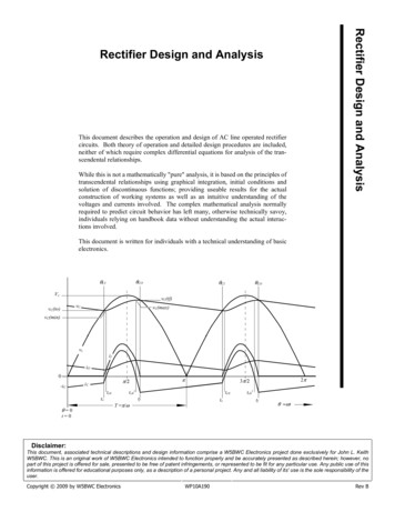
Rectifier Design and iO0-iCtc0tc0' 0t 0tc0tfto23 //iCtc0'totfT /tFigure 6. Equivalent Input Voltage, Capacitor Voltage, Forward Diode Current, Capacitor current and Output current versus t fora full-wave rectifier with shunt-capacitor filter.sumed resistive which has minimum effect on the results, except for outputripple current with a constant current load which, as just observed, is near zerobecause the regulator draws constant current over the range of the ripplevoltage.Qualitative Analysis of Voltages andCurrentsIn keeping with standard engineering practice, angular relationships withangles expressed in radians are presented in this document, in part to provideconsistency with the referenced published works and in part to simplify theanalysis. One other point of convention, in Figure 6 voltage and current areportrayed on a scale with a 0 starting point. Actually this is just a referencepoint in the angular rotation of vi as it passes through an angle of 0 radians. Theactual time from when voltage was first applied is unspecified but it is assumedsteady-state conditions are already established. More on this in the QuantitativeAnalysis where initial conditions are defined and the transit condition from theinstant of power application to steady-state is explored.Figure 6 provides critical insight into understanding a FW rectifier's voltagecurrent relationships. This busy graph, if studied carefully, will serve one well.The input voltage (vi) is a rectified voltage of the formvi Vm sin ( t to) - nvf, whereW5BWC Electronics9108 FM 1972 Gilmer, TX 756456 2 f and / T,February 2009
Rectifier Design and Analysiswhich is the half-cycle period of the incoming AC line voltage. 1,2 Figure 6shows this voltage starting at a phase angle of 0 and continuing through to 2radians, or one complete cycle of the incoming AC line voltage.For the circuit conditions portrayed in Figure 6, ve is the driving voltage andis related to vi by,ve RL(vi )Rs RLas well, the capacitor already has a charge at t 0, with a resultant voltage (vC)from which the first basic relationship is seen. Namely, the rectifier will notbecome forward biased until ve is equal to, or greater than, vC . This point intime is designated to signifying rectifier turn-on and the initiation of rectifiercurrent flow (if) which will increase over time as ve continues to increase fasterthan vC. Some texts also identify this point as CI, the cut-in angle of the inputvoltage that initiates current flow if. 3At to, vC is near, but not at its' minimum value. vC will reach its' minimumwhen if becomes equal to iO, or the instant iC 0. iC is negative whilesupplying the output current, which it does until if starts to flow at to, butduring the transition between to and tC0 (the point in time at which iC 0) thecapacitor supplies a decreasing amount of the output current until if suppliesthe entire output current. From this point if also begins to charge thecapacitor, iC becomes positive and vC begins to increase. Thus, the minimumripple voltage occurs not at rectifier turn-on, but a short time latter at tC0.As if begins to flow, it takes on a complex pulse form, that is dependent uponthe ratio of RS/RL, and the value of C. 4 This current pulse will peak before theincoming voltage does and will last until some time after the incoming voltagepeaks, a time designated as (tf), signifying turn-off of the rectifier - also a pointin angular rotation noted as ( CO) or the cut-off angle.As might rightfully be surmised, tf provides another critical point of insight.First, this is the point at which rectifier current stops and the capacitor resumesproviding the entire output current. Similar to the condition of vC at to, thepeak output voltage precedes this point by a slight amount, because if decreases as ve drops toward vC . The resultant current flow through the rectifierand source resistance is no longer supplying the entire output current, resultingin some amount of current again being drawn from the capacitor, in turncausing its' voltage to drop. Thus, the maximum ripple voltage occurs not atrectifier turn-off, but rather a short time prior when iC 0 at time tC0' .Second, starting at tf the capacitor will discharge at a rate that can be calculatedwith the basic exponential decay formula - assuming the load is resistive. Ifthe load is a constant current the capacitor voltage will decay linearly per thebasic differential equation relating charge and current in a capacitor. 4 TheThis is the general expression for an ac voltage with to representing time 0 and should not be confused withthe convention in this document of to representing the point at which the rectifier diode turns on. Also note, Tis 1/2f / and not the customary 1/f .2 Note that in the following calculations and Figures the diode static forward drop is subtracted from the actualinput voltage which then is identified as vi.3 Basic Electronics for Engineers and Scientists by Lueg and Reinhard 1972 International Textbook Company4 See Appendix B, Relationship of voltage and currents to RS, RL and C.1W5BWC Electronics9108 FM 1972 Gilmer, TX 756457February 2009
Rectifier Design and Analysisdischarge will continue through time until ve once again overcomes vc at whichpoint the process repeats, at the next to.And lastly, note vc does not perfectly track ve during the time the rectifier is on.This is because of the series resistance described earlier and is more pronounced the larger Rs, or if LLK is significant. Actually, vc can theoreticallytrack ve if Rs 0 (a source of infinite power), but the equation presented in thisdocument will not calculate if for this condition as it causes a divide by 0operation. Not to worry though, this is an impossible real world condition andif curiosity demands a solution, differential equations are presented in engineering texts, for instructive purposes, solving such a theoretical condition. 1FWBR or FWCT rectifier circuit design can be simplified by starting withsome rough estimates of performance. These can then be used to make morespecific calculations that will determine actual specifications for the key components.Handbook Design FactorsTable 1. First, consider the trade-offs between FWBR and FWCT circuits operating into a shunt-capacitor filter. 2Design Considerationrms secondary currentpeak secondary currentFWBR1.65IoFWCT1.15Ioidentical, but FWCT rms current is less thanFWBR by the 2Vo(0.7 to 0.95)*Vo(1.4 to 1.9)*Rectifier diodes PIV1.412.82Transformer utilization**PoorPoorerSecondary voltageVoltage regulation***PoorerpoorDepending upon load current.High peak to average ratio of currents in shunt-capacitor filter systems causepoor utilization of the transformer and poor power factor - see text for additionalinformation.The selection of topology may not be possible until after detailed calculationsare made. However, some guidelines are; FWCT requires a transformer withalmost twice the secondary voltage, the secondary rms current is only less bythe 2 and peak secondary current is the same as for FWBR, with primarycurrent very similar for either. Even though the FWCT also requires thecomplication of a center tap connection, it may still be preferable in highcurrent rectifiers where the additional diode's power loss and voltage drop aremore significant than the associated transformer complications.12W5BWC ElectronicsBasic Electronics for Engineers and Scientists by Lueg and Reinhard 1972 International Textbook CompanyReference Data for Radio Engineers Sixth Edition 1982 Howard W. Sams & Co., Inc.9108 FM 1972 Gilmer, TX 756458February 2009
Rectifier Design and AnalysisFirst Pass Approximations1 C 1RLvr/vc 0.6lnand,Rs 0.4CIn order to work through the detail calculations, it is necessary to estimateappropriate values for some of the unknowns, a task not as difficult as it mightfirst seem. Start with the desired output voltage, I will not belabor the point onhow to select this value, but some guidelines are;1) if the output feeds an electronic regulator, the minimumripple voltage must remain greater than the drop-out voltage at minimum line voltage and full load, but the greaterthe rms output voltage the greater the power dissipationand lower the efficiency;2) if the output will be used directly or minimum ripplevoltage is desired, it is primarily dependent upon loadresistance and the capacitor - to the extent the sourceresistance can charge the capacitor;3) the voltage regulation is primarily dependent upon the loadresistance and the source resistance and only slightly onthe capacitor;4) as well, the peak current is also primarily dependent uponthe load and source resistance so improving regulationwill increase peak current. 1, 2(1)(2)In a similar fashion, select the full-load output current. If the load is anelectronic regulator this will be a constant current. If the output is used0.560 Hz0.40.30.20.1010.110RL (Ohms)1001000Figure 7. Graph for estimating the capacitor value and maximum series resistance, given a desired ripple voltage (peak-to-peak) and load resistance. Graph is for power line frequency of 60 Hz.12W5BWC ElectronicsRadio Engineering by Frederick Terman, Sc.D., 2nd Edition, McGraw-Hill Book Company, Inc. 1937See Appendix B for further discussion.9108 FM 1972 Gilmer, TX 756459February 2009
Rectifier Design and Analysis0.550 Hz0.40.30.20.1010.110RL (Ohms)1001000Figure 8. Graph for estimating the capacitor value and maximum series resistance, given a desired ripple voltage (peakto-peak) and load resistance. Graph is for power line frequency of 50 Hz.directly, without electronic regulation, assume the load to be a resistanceequal to the desired rms output voltage divided by the full load outputcurrent.Selection of the shunt-capacitor will be finalized after the rms ripplecurrent is calculated, as this often is the controlling factor in it's value.As a first approximation select a capacitor that has a working voltagesomewhat higher than Vm with the AC line voltage at its' maximumvalue. Refer to specific manufacturers data for guidance.The starting point capacitance can be estimated by Equation (1) orFigure 7 (60 Hz) or Figure 8 (50 Hz). 1 This equation is based onselecting a desired ripple voltage (peak-to-peak), output load resistance(at full load), rms output voltage at full load, and line frequency. Theestimation is based on the assumption that the discharge time is 0.6 of ahalf-cycle period - which is sufficient to get started, remember the finalvalue will be selected after detail calculations. This also provides astarting point for selection of the transformer by establishing a maximum value for Rs using Eq. (2) or again reading Rs from the capacitancecurves of Figure 7 or 8. If these values seem unreasonable, then adjustthem accordingly and then run through the detail calculations torationalize.1W5BWC ElectronicsSee Appendix A for derivation of these equations.9108 FM 1972 Gilmer, TX 7564510February 2009
Rectifier Design and Analysis3025ve20voVolts& 15Amps10if50010520153025Time in mS (referenced to initial conditions)3540Figure 9. Relationship of voltages and currents over five half-cycles starting with initial conditions of ve vC t 0, for example in Fig. 10.tsioic18.56 VacViif25vf0.75 VRc0.04 Vo6500 uFRs6.0-C20RL Vo -0.48Figure 10. Example rectifier with Rs 0.51.15tn - 1tntsVeVe and Vo(Volts)tn - ts/29.025102410If(Amps)If58.58.79 A2322Ve and Vo(Volts) 217.5if6.76 A2021.13V1920.02V18.83 V18.53 V170012354Time (mS)67W5BWC Electronics3.08Figure 11. Equivalent circuit input voltage shown quantized into discrete0.25 mS voltage steps. Numerical data for example in Figure 10, aftersteady-state conditions are established.3.053.103.15Time (mS)3.203.25Firgure 12. Detail of the step in Figure 11 from 3.0 to3.25 mS. Expanded view of voltages and currentsover the duration of the step.9108 FM 1972 Gilmer, TX 75645116.56.0Vo180if7.0 (Amps)Ve58.0February 2009
Rectifier Design and AnalysisQuantitative AnalysisInitial Conditions and Surge CurrentsIn order to proceed with detail calculations, initial conditions must be defined.Even though these can be set at random, some advantage is had by using theinitial conditions shown in Figure 9. The AC input voltage alternately cyclesfrom a negative peak to a positive peak and again to a negative peak, crossingthrough 0 volts each direction. After full-wave rectification it has the unipolarform shown in Figure 9. If we pick a point on this rectified input voltagewhere it is going positive from 0 volts and define it as t 0 we have a logicalstarting point for initial conditions, especially if we let vC 0 at this point. ByOhms law, if vi vC 0, then all currents are also 0.So the instant power is applied the natural response of the rectifier circuit is forcurrent to flow like it would in any series RC circuit. Figure 9 shows this as ifleads vC and increases to a value well above steady-state conditions. Howeverthe total circuit response is also influenced by the forced component of therectified driving voltage. That is to say, if vi was a DC voltage the capacitorwould continue to charge, at a rate determined by the RsC time constant, untilfully charged. But since the forcing voltage is rectified AC, there may beinsufficient charge accumulated on C during this first half-cycle to establishsteady-state conditions. This is seen as vC increases but does not reach steadystate during the first half-cycle.The second half-cycle again charges C, this time from a starting voltage muchabove 0 and so by cycle's end vC is much nearer its' steady-state value than itwas at the end of the first half-cycle. This transit response is a function of thecircuit values and independent of the forcing voltage, depending on the actualvalues it may last several cycles, such as the example in Figure 9 takes fivehalf-cycles to reach equilibrium (steady-state).By starting calculations with these initial conditions we capture yet anotherimportant value - the repetitive surge forward current that may be expected forsevere over-loads. For rectifiers that feed an electronic regulator, this is lessimportant than for a rectifier that feeds a non-current limited load. Normallyan electronic regulator will manage output overloads, but if the rectifier doesnot have such protection it will be possible for severe overloads to pull vC to 0Volts, or nearly so. This will cause a repetitive surge forward current pulseeach half-cycle that is similar to initial turn-on.This is not to be confused with non-repetitive forward surge current (IFSM) thatsemiconductor manufacturers normally specify for a single cycle of either 50or 60 Hz. If a forward current of this magnitude becomes repetitive the diodejunction will be destroyed, whereas the repetitive surge forward current's rmsvalue must not exceed the diodes rms forward current rating (IFrms), alsodenoted as (IO) by some manufacturers.Worst case IFSM is limited only by the equivalent series reactance (resistanceand leakage inductance) of the transformer, the rectifier resistance and thecapacitor's ESR. Refer to Figure 9 to visualize a case where the initial conditions have the input voltage at its' maximum value rather than at 0, for thisexample a little over 25 Volts. For an ESR of 0.01 and a RS of 0.51 theW5BWC Electronics9108 FM 1972 Gilmer, TX 7564512February 2009
Rectifier Design and AnalysisReio - icicve icRcViVcRLVo Rcvo CCFigure 13. Equivalent circuit of Figure 4 with RS ( RS‘ nRd RW) and RL combined into Re and rectifier on,that is, during the angle of conduction CI to CO. Alsonote ve replaces vi according to Equation (5).Figure 14. Equivalent circuit of Figure 4 with RS removed, that is the rectifier off during the angle of COto CI . Note during the rectifier off time, the circuit isa simple RC circuit as the discharge of C supplies theentire output current.surge current is almost 50 Amps. This current surge will decay quicklylasting only a fraction of the AC cycle, i.e. limited by the time constant ofRSC, but even so, it is critical that it not exceed IFSM. It is prudent to includean appropriately sized NTC thermistor, known as "inrush current limiter" inthe primary side of the transformer to reduce this inrush current to a safevalue.In order to determine the current and voltages in Figure 9 it is necessary tomake repeated calculations of forward current, if , starting at the initialcondition and for each step thereafter until the first half-cycle tf is reached,using Equations (3) through (11).1First, the equivalent circuit of Figure 4 is reduced by Thevenin’s theorem toFigure 13, using Equations (3) through (6).(3)(4)RsRLRe Rs RL(6)vi (5)Rs Rs' nRd Rwve RL(vi )Rs RLVi (rms) sin(t - ts/2) - nvfFigure 13 represents the rectifier circuit during the time forward currentflows through the diodes, that is during the angle of conduction from CI toCO. Equation (7) is an approximation of the differential equation for ic(7)COic(t) ve(tn) - vc(tn -1)Re RcCIwhere ve is the driving voltage, calculated at the midpoint of the step from(tn -1) to tn, and vc(tn -1) is the voltage on the capacitor at the beginning ofstep tn. The forward current is time dependent, that is its' value depends onvc (which is also time dependent) at each instant of time. For this reason thecalculations are made using quantized steps, see Figure 11 and 12, to1W5BWC ElectronicsA similar approach, not developed in detail, is presented in Circuits, Devices, and Systems Second printing byRalph J. smith John Wiley & Sons inc., New York9108 FM 1972 Gilmer, TX 7564513February 2009
Rectifier Design and Analysiscalculate discrete equivalent values for if. Note the restriction that ts RsC/2,which is necessary for the equation to track the rate of change of the AC inputvoltage.This yields a value at only one point in time and in order to calculate a value atthe next step in time (which must be done sequentially) the approximation ofthe time integral of vc must be calculated and added to vc(tn -1) to obtain the newvc(tn -1) for the next step of n . This is done using Equation (8) after which theother time dependent variables are calculated using Equations (9) through (11).if (t) Forward diode current at time tn 1 for FWCT or 2 for FWBRvf each diode forward voltage drop at nominalioRd dynamic resistance of diodesRc capacitor resistance (ESR)Rs' xfmr secondary DC resistance 1/n2(primary resistance)to the time at which the diodes turn ontf the time at which the diodes turn offTrig functions in radians - for trig functions in degrees multiply by 57.3 (degrees / radian). 2 f (radians per second)These equations involve many time-variant valueswritten with italic parenthesis not to be confusedwith the operation of multiplication written withstandard parenthesis, for example;(v)(t) the value of v multiplied times thevalue of t, whereas,v(t) voltage at time t.In most instances the meaning is clear due to context, but if doubt exists use this guide.(8)(9)CO(ic(tn))tsvc(t) vc(tn -1) CCOvo(t) (ic(tn))Rc vc(tn)CICI(10)(11)COCOif(t) ic(tn) io(tn)io(t) (vo(tn))/RLCICISo, the process is to calculate an instantaneous forward current and integratethe capacitor charge over the time of the step to establish the conditions tocalculate the next step, continuing the process until tf is reached.After tf , the capacitor voltage is found using Equation (14), once Equations(12) and (13) are solved.(12)(13)CIic(t) -io -vc(tn -1
W5BWC Electronics 9108 FM 1972 Gilmer, TX 75645 February 2009 4 Rectifier Design and Analysis variant values and upper case I and V represent peak or rms values, noted as used. V i which also is V rms is the transformer's secondary rms voltage measured from one end of the