Transcription
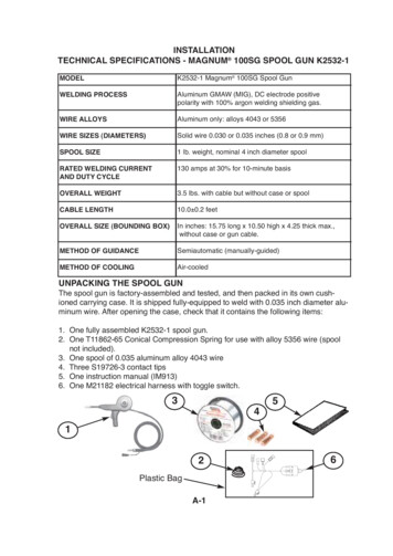
INSTALLATIONTECHNICAL SPECIFICATIONS - MAGNUM 100SG SPOOL GUN K2532-1MODELK2532-1 Magnum 100SG Spool GunWELDING PROCESSAluminum GMAW (MIG), DC electrode positivepolarity with 100% argon welding shielding gas.WIRE ALLOYSAluminum only: alloys 4043 or 5356WIRE SIZES (DIAMETERS)Solid wire 0.030 or 0.035 inches (0.8 or 0.9 mm)SPOOL SIZE1 lb. weight, nominal 4 inch diameter spoolRATED WELDING CURRENTAND DUTY CYCLE130 amps at 30% for 10-minute basisOVERALL WEIGHT3.5 lbs. with cable but without case or spoolCABLE LENGTH10.0 0.2 feetOVERALL SIZE (BOUNDING BOX)In inches: 15.75 long x 10.50 high x 4.25 thick max.,without case or gun cable.METHOD OF GUIDANCESemiautomatic (manually-guided)METHOD OF COOLINGAir-cooledUNPACKING THE SPOOL GUNThe spool gun is factory-assembled and tested, and then packed in its own cushioned carrying case. It is shipped fully-equipped to weld with 0.035 inch diameter aluminum wire. After opening the case, check that it contains the following items:1. One fully assembled K2532-1 spool gun.2. One T11862-65 Conical Compression Spring for use with alloy 5356 wire (spoolnot included).3. One spool of 0.035 aluminum alloy 4043 wire4. Three S19726-3 contact tips5. One instruction manual (IM913)6. One M21182 electrical harness with toggle switch.35412Plastic BagA-16
INSTALLATIONSAFETY PRECAUTIONSWARNINGELECTRIC SHOCK CAN KILL. Turn the input power OFF at the welding power source beforeinstallation or changing drive rolls and/or guides. Do not touch electrically live parts. When inching with the gun trigger, electrode and drive mechanismare "hot" to work and ground and could remain energized severalseconds after the gun trigger is ---------LOCATING SPOOL GUN COMPONENTS AND FEATURES(See Figure 1.A for Items 1 thru 6)1. Gas Cone Assembly and Contact Tip.2. Straightened Gun Tube Assembly.3. 1/4-Turn Locking Collar.4. Trigger Assembly.5. Spool Cover: Provides easy, wideopen access to spool and wiredrive.6. Locking Knob: Captive in spoolcover.FIGURE A.1553124Left Side View(See Figure A.2 for these following items)7. Integrated Single-Piece Cable:The Magnum design providesneat and clean appearance; simplifies cable management andreduces entanglements.8. Standard Durable Strain ReliefClamp.9. Three Captive Hex Nuts.7FIGURE A.289Right Side ViewA-2
INSTALLATIONASSEMBLY OF ITEMS INSIDE THE MAGNUM SPOOL GUNFIGURE A,34TOP VIEW723189Spool Cover and lefthandle removedMASTER KEYMachine Connections16324P6 CONNECTOR PINOUT1. Liner Assembly feeds all specifiedwire.2. Drive Roll: This Drive Roll feeds allspecified wires.3. Idle Roll Assembly: Non-adjustabletension setting for all specified wires4. Incoming Wire Guide: Highly wearresistant.5. P6 Connector Control Leads: MotorPowerandTrigger.(SeeMaintenance Section for moredetails)6. Welding Power and Shielding GasMachine connection (Sealed with 2o-rings).7. Locking Knob: Independently retainsthe wire spool on the spindle.8. Liner Assembly: Includes a gas sealwith the cable connector and is theoutgoing wire guide.9. Only 4 sub-assemblies: gun tube;cable; wire drive; trigger.10. Conical spring (not shown) servesas the spool brake (use only withaluminum alloy 5356).A-3
INSTALLATIONSAFETY PRECAUTIONSWELDING MACHINESCAUTION Read and understand the welding machineʼs instruction manual and all hazard warnings on equipment and in the manual. Wear the proper personal protective equipment for welding,including but not limited to, safety glasses, hearing protection,welding helmet, welding gloves, and welding ---------SPOOL GUNWARNINGELECTRIC SHOCK CAN KILL. The spool of wire may fall out of the gun if the locking knob isnot installed. Metal parts may be at welding voltage (electrically "hot"). Metal parts remain at welding voltage for several seconds after trigger isreleased. Read warning label on gun. This product shall not be used in precipitation, or in wet or damp ------------A-4
INSTALLATIONRECOMMENDED WELDING MACHINESMACHINE NAMEK-NUMBERCODE NUMBERPOWER MIG 216POWER MIG 215XTPOWER MIG 180CPOWER MIG 140CPOWER MIG 180 DUALPOWER MIG 180C AUPOWER MIG 180C CEPOWER MIG 140TPOWER MIG 1-1K2470-1K2472-1PRO CORE 125K2479-1PRO MIG 140K2480-1WELD PAK 125 HDK2513-1WELD PAK 140 HDK2514-1MIG PAK 140K2658-1EASY CORE 125K2696-1EASY MIG 140K2697-1WORK PAK 125K2699-1CORE PACK 125K2785-1PRO MIG 180K2481-1WELD PAK 180HDK2515-1MIG PAK 180K2659-1SP-140TK2688-1SP-180TK2689-1EASY MIG 11505INSTALLATION OF M21182 HARNESSAND SELECTOR SWITCHNOT REQUIREDNOT REQUIREDREQUIREDREQUIREDNOT REQUIREDREQUIREDREQUIREDREQUIREDREQUIREDSPOOL GUN USE NOT AVAILABLEREQUIREDNOT REQUIREDREQUIREDSPOOL GUN USE NOT AVAILABLEREQUIREDNOT REQUIREDREQUIREDNOT REQUIREDREQUIREDSPOOL GUN USE NOT AVAILABLEREQUIREDNOT REQUIREDREQUIREDSPOOL GUN USE NOT AVAILABLEREQUIREDSPOOL GUN USE NOT UIREDREQUIREDNOTE: THE MACHINE CODE NUMBER IS LISTED ON THE BACK OF THE MACHINE.A-5
INSTALLATIONNOTE: Installation of the M21182 harness and spool gun selector switch isnot required for all machines. If a spool gun switch is pre-installed in themachineʼs wire drive compartment, then the SPOOL GUN / WIRE DRIVESLECTOR SWITCH INSTALLATION SECTION can be disregarded.SPOOL GUN / WIRE DRIVESELECTOR SWITCHINSTALLATIONA1. Install the M21182 electrical adapterharness that came with the spool gunper the following instructions.ELECTRIC SHOCK CAN KILL.WARNING5. Remove screws from cover.(A) is the location of two 3/4” longscrews.2. --------------------------------OPEN THE MACHINE3. Remove two 5/16“ hex hinge screwsfrom door.6. Remove cover.AB4. Remove ten 5/16“ hex screws fromcover.7. If machine has a plastic handle (A),then remove screw (B).A-6
INSTALLATIONELECTRICAL CONNECTIONS544A(Male)P7543A(Female)Toggle SwitchJ3J7 (10-pin)J8 (6-pin)P8 (6-pin)P7 (10-pin)8. Adapter harness. All 6 connectionsshown are used, and each one isunique. (Proceed as follows)10. Connect harness P7 (10-pin) toboard J3 (10-pin).IF MACHINE DOES NOT HAVE OPTIONALSPOT TIMER. (11.A. thru 11.D.)P5P3J511.A. Remove P5 (6-pin) fromboard J5 (6-pin).J39. A. Remove P3 (10-pin) from boardJ3 (10-pin).J8P5P3J711.B. Connect P5 (6-pin) to harness J8 (6-pin).P8J59.B. Connect P3 (10-pin) to harness J7 (10-pin).11.C. Connect harness P8 (6-pin)to board J5 (6-pin).A-7
INSTALLATIONP8544AJ9543A11.D. Find assembled pair of machineterminals (leads 543A & 544A)and disconnect. Go to step 13.12.C. Connect adapter harness P8 (6pin) to spot timer harness J9 (6pin).IF MACHINE DOES HAVE OPTIONAL SPOTTIMER.(12.A. thru 12.D.)544AJ9P512.A. Remove P5 (6-pin) from spottimer harness J9 (6-pin).543A12.D. Find assembled pair of machineterminals (leads 543A & 544A)and disconnect.BJ8AP512.B. Connect P5 (6-pin) to adapterharness J8 (6-pin).13. Connect terminals:(A) connect machine male (lead543A) to adapter harness female(lead 543A).(B) connect machine female (lead544A) to adapter harness male(lead 544A).14. Ensure that the locking tabs on allconnectors are latched closed.A-8
INSTALLATIONMOUNTING THE SWITCH15. Remove the plug button from thepanel hole.16. Plug button is no longer needed.Discard.18. Install switch into panel hole.Ensure washer tab is fully seatedinto smaller hole.19. Reinstall mounting nut onto switch.Wrench tighten.RE-ASSEMBLE MACHINE ASFOLLOWS:17. Remove mounting nut from switch.Keep mounting nut for installation.20. Reinstall screw into plastic handle (ifso equipped).21. Reinstall cover.22. Reinstall door.23. Reconnect input power to themachine.A-9
INSTALLATIONROUTINE WELDING MACHINE PREPARATIONWARNINGELECTRIC SHOCK CAN KILL.1. Disconnect input power to the -----------------------------2. Machine polarity setting: Set to DC electrode positivepolarity per the machineʼs Instruction Manual.3. Gas selection and flow rate: Connect 100% weldinggrade argon gas supply to the machineʼs gas solenoidvalve. Set the supply regulator to deliver a gas flow rateof 20 to 50 SCFH thru the spool gun.]4. Flip the machineʼs wire drive selector switch (behind theaccess door) to "Magnum 100SG". (See Figure A.4)FIGURE A.4PREPARING THE SPOOL GUNWARNINGELECTRIC SHOCK CAN KILL.1. Disconnect input power to the -----------------------------2. The Conical Spring is used as the spool brake only whenfeeding the stronger and harder aluminum alloy 5356.The Conical Spring must be removed from the spool gunwhenever using the softer aluminum alloy 4043.A-10
INSTALLATIONLOADING ALUMINUM WIRE1. Remove gas cone and contact tip.Remove spool cover by unscrewingcaptive locking knob.FIGURE A.52. Remove locking knob from spindlebolt by unscrewing it.FIGURE A.63. Select wire alloy and diameter needed. Alloy 4043 and 0.035 wire sizeshown. Remove packaging and datasheet from wire spool.FIGURE A.74. Extend approximately 12 inchesof wire from spool. Straighten itout by back-bending it. Use careto prevent the wire from dereeling.FIGURE A.85. Cut off bent end of wire, leavingstraight section.FIGURE A.96. Gently pull open the idle rollassembly to expose the drive rollgroove.SizeAlloyA-11FIGURE A.10
INSTALLATION7. Guide straightened wire through inletwire guide and toward drive rollgroove.FIGURE A.1110a. Alloybackontoknob11.4043: Roll up remaining wireonto spool and place spoolgun spindle. Install lockingand finger-tighten. Go to stepFIGURE A.148. While holding open the idle roll, slideend of wire through drive rollʼsgroove and toward gun tube liner.FIGURE A.1210b. Alloy 5356: Install Conical Spring,small end first, onto gun spindle(A). Roll up remaining wire backonto spool and place spool ontogun spindle. Install locking knoband finger-tighten.FIGURE A.15A9. Slide the wire into the liner until itextends approximately 1 inch beyondthe end of the gas diffuser. Releaseidle roll tab without snapping it.FIGURE A.1311. Grasp the free end of the wire at thegas diffuser and slowly pull approximately 12 to 24 inches of wirethrough the spool gun. There shouldonly be 1 to 2 lbs. of resistance. Ifforce is greater than 2 lbs. wire isbinding in the gun (also seeTroubleshooting guide).FIGURE A.16A-12
INSTALLATION12. Cut off excess wire 1 to 2 inchesfrom gas diffuser. Install properlysized contact tip slightly past handtight. Install gas cone and handtighten.FIGURE A.17CONNECTING THE GUN TO THEWELDING MACHINE1. Disconnect input power to themachine.2. Make sure that the gun locking knobis loosened. (See Figure 20).13. Reinstall spool cover. 1: tuckcoverʼs tab in place at arrow andhold with thumb. 2: swing coverclosed. 3: finger-tighten lockingknob. 4: check for uniform fit allaround cover.FIGURE A.183. Fully insert gun cable connection(welding power and gas supply) intomachine. Note that the master Keyway for P6 connector is located atthe arrow.FIGURE A.19P6ConnectorKey way41324. Check that the cable connectorʼsend is flush with insulator at A.Tighten gun locking knob (B) ontocable connector.FIGURE A.20BA-13A
technical specifications - magnum 100sg spool gun k2532-1 model welding process wire alloys wire sizes (diameters) spool size rated welding current and duty cycle overall weight cable length overall size (bounding box) method of guidance method of cooling k2532-1 magnum 100sg spoo